EP0699610B1 - Vorrichtung zum Schneiden und klebstofflosen Anbringen des Bahnanfangs für eine neue Wickelrolle auf den Wickelkern eines Wicklers - Google Patents
Vorrichtung zum Schneiden und klebstofflosen Anbringen des Bahnanfangs für eine neue Wickelrolle auf den Wickelkern eines Wicklers Download PDFInfo
- Publication number
- EP0699610B1 EP0699610B1 EP19950440044 EP95440044A EP0699610B1 EP 0699610 B1 EP0699610 B1 EP 0699610B1 EP 19950440044 EP19950440044 EP 19950440044 EP 95440044 A EP95440044 A EP 95440044A EP 0699610 B1 EP0699610 B1 EP 0699610B1
- Authority
- EP
- European Patent Office
- Prior art keywords
- pivoting
- arms
- strip
- core
- fact
- Prior art date
- Legal status (The legal status is an assumption and is not a legal conclusion. Google has not performed a legal analysis and makes no representation as to the accuracy of the status listed.)
- Expired - Lifetime
Links
Images


Classifications
-
- B—PERFORMING OPERATIONS; TRANSPORTING
- B65—CONVEYING; PACKING; STORING; HANDLING THIN OR FILAMENTARY MATERIAL
- B65H—HANDLING THIN OR FILAMENTARY MATERIAL, e.g. SHEETS, WEBS, CABLES
- B65H19/00—Changing the web roll
- B65H19/22—Changing the web roll in winding mechanisms or in connection with winding operations
- B65H19/28—Attaching the leading end of the web to the replacement web-roll core or spindle
Definitions
- the present invention relates to the field of winding machines strip materials for the production of coils and relates to a device cutting and applying, without glue, the strip start of a new reel on a reel mandrel.
- the winding of strips by means of winding machines poses generally the problem, on the one hand, of the cutting of the strip and, on the other hand, of the correct application of the end of the strip to the mandrel after cutting. AT this effect, it is possible to make the cut while the strip is running following a principle called cutting on the fly, in which a knife is thrown in the path of the strip and the cut end of the strip is projected onto a mandrel pre-glued or fitted with one or more adhesive strips of receiving said end, which is further clamped on said mandrel by the strip during its winding.
- strip materials require winding on the receiving mandrel without applying glue or adhesive tape, by simple pinching of the first coiled turns, with a view to their transformation later.
- Such a winding is particularly difficult to achieve, avoiding any risk of slipping when starting the winding in the case for winding relatively rigid materials.
- this document GB-A-1 154 662 describes a first means pivoting partially surrounding the new mandrel and a second means pivot for making the cut of the strip to be wound.
- This second plea swivel consists, in fact, only of a serrated knife, extending over the entire width of the pivoting means and disposed at the end of a pressurized air box and tending to carry out the introduction of the beginning of the strip into the shell formed by the first pivoting means, upon arrival at the end of the knife cutting stroke, this introduction being favored by air blowing.
- blowing air due to a cut along a serrated line, in case of winding of a particularly material flexible, blowing air combined with rapid rotation may not present a sufficient effectiveness to avoid folding of the tips of the teeth.
- DE-A-39 00560 describes a device for winding a start of strip on a mandrel, this device consisting of a pair of prongs each provided with an articulated partial closing lever, said claws and their articulated levers being interconnected by shafts guided in rotation, on which are mounted parallel belts.
- the device can be caused to extend partially around of the new mandrel, on which the strip must be wound, the belts being intended, on the one hand, to apply the start of strip to the new mandrel, and, on the other hand, to guide it around said mandrel until at least one revolution winding, this avoiding any overturning of the front end of the strip or during the winding of the first turn.
- This device does not, however, provide a second means intended to perfect the introduction of the strip into the device, as well as its hold without crease during the realization of the first turn. Indeed, it is not planned no movable means tending to follow the movement of the end of the strip at wrap.
- the object of the present invention is to overcome these drawbacks by proposing a cutting and application device making it possible to surround a new mandrel over most of its periphery to promote winding of a strip start following a cut of said strip, this cut being a straight cut, frank and not serrated.
- the first pivoting means comprises a support crosspiece a cross-cut knife in the form of a carriage guided on the cross member and actuated by a jack and cooperating with a transverse anvil also extending between arms forming a pivoting frame constituting the first pivoting means, said anvil forming a stop for an anvil analog fixed to the corresponding end of the second pivoting
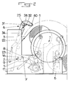
- the device for cutting and applying, without glue, the start of a new strip coil on a mandrel 1 of a reel essentially consists of a first pivoting means 2 for cutting the strip 3 to be wound up and applying the end of the latter on a new mandrel 1, without prior gluing of the latter, and by a second pivoting means 4 for introducing, after cutting, the end of the strip 3 in the first pivoting means 2 and for applying said strip 3 on the new mandrel 1.
- the first pivoting means 2 is constituted by a pivoting frame formed by a pair of arms 5 extending parallel near the edges of the frame 6 of the winding machine, interconnected by a cross member 7 supporting a cross-cut knife 8 and each actuated by a jack 11 and by a first set of parallel elastic belts 9, endless, mounted on at least a pair of parallel shafts 10, guided in rotation, at their ends on the arms 5 ( Figures 1 to 3).
- the parallel elastic belts 9 are preferably mounted on three trees arranged in parallel so as to form in vertical section a triangle, one of whose sides formed by the belts 9 is deformable elastically by application against the mandrel 1 and one of the vertices of which is formed by one of the shafts 10, is movable by pivoting, by means of a pair of arms 12, represented in FIG. 3 by a simple center line. So when pivoting of the arms 5 carrying the shafts 10 with the belts 9 and of the application said belts 9 on the mandrel 1, there is a tension of the belts 9 due to their deformation during winding on the mandrel 1, this tension being compensated by a pivoting of the shaft 10 mounted on the arms 12.
- the elastic belts 9 are loaded in the rest position by a tensioning device preliminary constituted by a roller or a shaft 13 pivotally mounted on the chassis formed by the arms 5 by means of pivoting levers 14, shown in Figure 3 by a center line, said levers being loaded by return springs (not shown), tending to tension the belts 9 between the two fixed shafts 10 in the direction of the new mandrel 1.
- the arms 5 carrying the shafts 10 advantageously have a cutting into a portion of a circle 15 extending between the bearings of the two shafts fixed 10 for supporting the belts 9.
- a passage for the mandrel 1 is released on the arms 5 allowing perfectly the application of the belts on said mandrel 1 without risk of contact of the arms 5 with the ends of the mandrel 1 or with the latter's support hubs.
- teeth 16 are arranged at regular intervals on a shaft 17 extending between the arms 5 near their free end, that is to say near the bearings of the fixed shaft 10 most the exterior with respect to the pivoting arms 5, the ends of said teeth 16 projecting beyond the free ends of the arms 5 and extending pivotally towards the mandrel 1 inwards relative to the cut in a portion of a circle 15, these pivoting teeth 16 being loaded at their other end by springs of return 18 and coming into abutment against stops 19, the return springs and stops being advantageously mounted on crosspieces connecting the arms 5.
- the first pivoting means has beak-shaped elements formed by the teeth 16 and tending to apply intimately the end of the strip to be wound on the chuck 1.
- the cross-cut knife 8 is in the form of a carriage guided on the cross-member 7 and actuated by a jack and cooperates with a transverse anvil 20 also extending between the arms 5, this so-called anvil 20 forming a stop for a similar anvil 21 fixed at the end corresponding to the second pivoting means 4, the cutting plane of the knife 8 preferably being located near the axis of the lower fixed shaft 10 of guide and support of the first set of parallel elastic belts 9 (figure 3).
- the second pivoting means 4 is constituted by two parallel arms upper 22, pivotally mounted on the chassis 6 of the unwinding machine and each actuated at one end by a jack 23, their other end having a hook shape in an arc 24, and by a set 25 of application of the end of the strip on the mandrel 1 extending between the arms 22.
- the assembly 25 for applying the strip end to the mandrel 1 is constituted by a second train of parallel elastic belts 26, without end, mounted on at least two pairs of parallel shafts 27 extending between the arms superiors 22.
- the parallel elastic belts 26 are preferably mounted on three parallel shafts 27 forming a triangle with variable section, one of which sides formed by the belts 26 is elastically deformable by application against the mandrel 1 and one of the vertices of which is formed by one of the shafts 27, is pivotally movable, via a pair of arms 28 (shown by their center line in Figure 3).
- the elastic belts 26 are loaded in the rest position by a tensioning device preliminary consisting of a roller or a shaft 29 pivotally mounted between the upper arms 22 by means of pivoting levers 30, represented by their center line in Figure 3, said levers being loaded by return springs (not shown), tending to tension the belts 26 between the two fixed shafts 27 in the direction of the new mandrel 1.
- the application assembly 25 of the strip end on the mandrel 1 is advantageously mounted, with possibility of movement, between the upper arms 22, by means of two support carriages 31 guided in rails in an arc 32, provided on the corresponding faces of the upper arms 22, by means of rollers 33, one at least said carriages 31 being actuated in displacement by means of a cylinder 34 ( Figure 2).
- This embodiment allows, by application of the assembly 25 on the new mandrel 1, to start the winding of the strip on said new mandrel 1, by movement of the carriages 1 in the position shown in broken line at the end in FIG.
- the second pivoting means 4 is advantageously provided, between the support carriages 31, at regular intervals, with staggered arrangement by relative to the teeth 16, of longitudinal guide claws 35, the end of which facing the teeth 16 moves away from the mandrel 1.
- the shafts 27 of guide of the elastic belts 26 are advantageously constituted by a plurality of short rollers mounted on a rotating guide axis simultaneously forming a support for the longitudinal guide claws 35.
- the rails of guiding in an arc of a circle 32 are advantageously provided, on their turned side outwardly of the arms 22, of a rack 36 meshing with a pinion corresponding 37 guided on the carriage 31, the pinions 37 of the two carriages 31 of support of the assembly 25 being interconnected by a rigid shaft. So it is possible to provide only a single actuator 34 for actuating a carriage 31, the actuation of this single carriage 31 having the effect, by meshing of the pinion 37 corresponding with the rack 36, to rotate corresponding to the pinion 37 of the other carriage 31 and, thus, by meshing with the corresponding rack 36, synchronous drive and displacement of said other carriage 31.
- each arm upper 22 is provided at its free end 24 in the form of a hook with a stop 38 intended to cooperate with an adjustable stop 39 provided on the arms 5 of the first pivoting means 2.
- the contact between these two stops corresponds to the strip cross-sectional position, in which the anvils 20 and 21 tighten said strip for cutting by the knife 8.
- the second pivoting means 4 is provided, between the hook-shaped ends in an arc 24 of the arms 22, of a roller transverse 40 for deflecting the strip to be cut and wound.
- This roll 40 is especially intended to bring the strip to be cut into its position pinching by anvils 20 and 21.
- the device for cutting and applying the start of a strip new coil on a reel mandrel works as follows:
- the operator who has previously mounted a new non-glued mandrel 1, initiates the procedure cutting the strip and applying the end to the new mandrel 1.
- the drive of the full reel is stopped and the first pivoting means 2 is then tilted by means of the jacks 11 in its position shown in the Figure 1, in which the first set of elastic belts 9 is applied in an arc of circle around the mandrel 1 and the second pivoting means 4 is tilted by via the jacks 23, also in the position shown in FIG. 1.
- the strip is deflected by the roller 40 and is brought between the anvils 20 and 21.
- the cutting knife transverse 8 is then actuated, then the assembly 25 is moved by the carriages 31 actuated by the cylinder 34 and moving in synchronism thanks to the pinion 37 meshing with the racks 36 of the guide rails 32, in order to bring the cut end of the strip between the end of the belts 9 and the new chuck 1.
- the progress of the various operations can be controlled by a programmable controller or the like, so the operator only needs to set up the new mandrel and integrate the different parameters winding, namely the length of the wound strip or the reel diameter, etc.
- the strip to be wound is stored in a tape accumulator provided upstream.
- the invention it is possible to make a cut and a perfect application of the start of a strip to be wound on a new mandrel, without bonding, in particular in the case of winding fragile materials.
Claims (12)
- Vorrichtung zum Schneiden und klebstofffreien Anbringen des Bahnanfangs für eine neue Wickelrolle auf dem Wickelkern (1) eines Wicklers, bestehend im wesentlichen aus einer ersten verschwenkbaren Einrichtung (2) zum Schneiden der aufzuwickelnden Bahn (3) und zum Anbringen des Endes dieser Bahn auf einem neuen Wickelkern (1) ohne vorhergehenden Klebstoffauftrag auf diesen und aus einer zweiten verschwenkbaren Einrichtung (4) zum Einführen des Endes der Bahn (3) nach dem Schneiden in die erste verschwenkbare Einrichtung (2) und zum Anbringen der Bahn (3) auf dem neuen Wickelkern (1), wobei die zweite verschwenkbare Einrichtung (4) eine Einheit (25) zum Anbringen des Bahnendes auf dem Wickelkern (1) aufweist, die sich zwischen Armen (22) erstreckt, die auf dem Rahmen (6) der Abwickelmaschine verschwenkbar montiert sind, dadurch gekennzeichnet, daß die erste verschwenkbare Einrichtung (2) einen Querschenkel (7) zum Tragen eines Querschneidemessers (8) aufweist, das die Form eines auf dem Querschenkel (7) geführten und durch eine Kolbenzylindereinheit betätigten Wagens hat und mit einem Queramboß (20) zusammenwirkt, der sich ebenfalls zwischen Armen (5) erstreckt, die einen die erste verschwenkbare Einrichtung (2) darstellenden verschwenkbaren Rahmen bilden, wobei dieser Amboß (20) einen Anschlag für einen entsprechenden Amboß (21) bildet, der am entsprechenden Ende der zweiten verschwenkbaren Einrichtung (4) befestigt ist, wobei die Schneidebene des Messers (8) vorzugsweise in Nähe der Achse einer unteren feststehenden Welle (10) zum Führen und Tragen eines ersten Satzes von parallelen elastischen Riemen (9) gelegen ist.
- Vorrichtung nach Anspruch 1, dadurch gekennzeichnet, daß die parallelen elastischen Riemen (9) vorzugsweise auf drei Wellen montiert sind, die parallel so angeordnet sind, daß sie im vertikalen Schnitt ein Dreieck bilden, von dem eine der von den Riemen (9) gebildeten Seiten durch Andrücken an den Wickelkern (1) elastisch verformbar ist und von dem eine der Ecken, die von einer der Wellen (10) gebildet wird, durch Verschwenken über ein Paar von Armen (12) beweglich ist, und daß die Riemen in Ruhestellung durch eine Vorspannungsvorrichtung belastet sind, die aus einer Walze oder aus einer Welle (13) besteht, die auf dem von den Armen (5) gebildeten Rahmen über Schwenkhebel (14) verschwenkbar montiert ist, wobei diese Schwenkhebel durch Rückholfedern belastet sind, die bestrebt sind, die Riemen (9) zwischen den beiden feststehenden Wellen (10) in Richtung auf den neuen Wickelkern (1) zu spannen.
- Vorrichtung nach einem der Ansprüche 1 und 2, dadurch gekennzeichnet, daß Zähne (16) in regelmäßigen Abständen auf einer Welle (17) angeordnet sind, die sich zwischen den Armen (5) in Nähe deren freien Endes, d.h. in Nähe der Lager der feststehenden Welle (10) erstreckt, die sich bezüglich der verschwenkbaren Arme (5) am weitesten außen befindet, wobei die Enden dieser Zähne (16) über die freien Enden der Arme (5) hinausragen und sich bei Verschwenken auf den Wickelkern (1) zu bezüglich des kreisbogenförmigen Ausschnittes (15) nach innen erstrecken und wobei diese verschwenkbaren Zähne (16) an ihrem anderen Ende durch Rückholfedern (18) belastet sind und an Anschlägen (19) in Anschlag kommen, wobei die Rückholfedern und die Anschläge auf die Arme (5) verbindenden Querschenkeln montiert sind.
- Vorrichtung nach Anspruch 1, dadurch gekennzeichnet, daß die Einheit (25) zum Anbringen des Bahnendes auf dem Wickelkern (1) mit Bewegungsmöglichkeit zwischen den oberen Armen (22) mit Hilfe von zwei Tragwagen (31) montiert ist, die in auf den entsprechenden Seiten der oberen Arme (22) vorgesehenen kreisbogenförmigen Schienen (32) über Rollen (33) geführt sind, wobei mindestens einer der Wagen (31) mit Hilfe einer Kolbenzylindereinheit (34) in Bewegung versetzt wird.
- Vorrichtung nach einem der Ansprüche 1 und 4, dadurch gekennzeichnet, daß die Einheit (25) zum Anbringen des Bahnendes auf dem Wickelkern (1) aus einem zweiten Satz von parallelen elastischen endlosen Riemen (26) besteht, die auf mindestens zwei sich zwischen den oberen Armen (22) erstreckenden, parallelen Wellen (27) montiert sind und auf den Tragwagen (31) geführt sind.
- Vorrichtung nach einem der Ansprüche 4 und 5, dadurch gekennzeichnet, daß die parallelen elastischen Riemen (26) auf drei parallelen Wellen (27) montiert sind, die ein Dreieck mit veränderlichem Querschnitt bilden, von dem eine der von den Riemen (26) gebildeten Seiten durch Andrücken an den Wickelkern (1) elastisch verformbar ist und von dem eine der Ecken, die von einer der Wellen (27) gebildet wird, durch Verschwenken über ein Paar von Armen (28) beweglich ist.
- Vorrichtung nach einem der Ansprüche 5 und 6, dadurch gekennzeichnet, daß die parallelen elastischen Riemen (26) in Ruhestellung durch eine Vorspannungsvorrichtung belastet sind, die aus einer Walze oder aus einer Welle (29) besteht, die zwischen den oberen Armen (22) über Schwenkhebel (30) verschwenkbar montiert ist, die durch Rückholfedern belastet sind, die bestrebt sind, die Riemen (26) zwischen den beiden feststehenden Wellen (27) in Richtung auf den neuen Wickelkern (1) zu spannen.
- Vorrichtung nach einem der Ansprüche 1 und 3 bis 5, dadurch gekennzeichnet, daß die zweite verschwenkbare Einrichtung (4), um einen einwandfreien Übergang des Bahnanfangs vom Austritt der ersten verschwenkbaren Einrichtung (2) und insbesondere von den verschwenkbaren Zähnen (16) auf die Einheit (25) zu gewährleisten, zwischen den Tragwagen (31) in regelmäßigen Abständen in einer bezüglich der verschwenkbaren Zähen (16) versetzten Anordnung mit Längsführungsklauen (35) ausgerüstet ist, deren den verschwenkbaren Zähnen (16) zugewandtes Ende sich vom Wickelkern (1) entfernt.
- Vorrichtung nach Anspruch 8, dadurch gekennzeichnet, daß die Wellen (27) zur Führung der elastischen Riemen (26) aus einer Vielzahl von Rollen geringer Länge bestehen, die auf einer die Drehung führenden Achse montiert sind, die gleichzeitig einen Träger für die Längsführungsklauen (35) bildet.
- Vorrichtung nach Anspruch 4, dadurch gekennzeichnet, daß die kreisbogenförmigen Führungsschienen (32) auf ihrer dem Äußeren der Arme (22) zugewandten Seite mit einer Zahnstange (36) versehen sind, die mit einem entsprechenden, auf dem Wagen (31) geführten Zahnrad (37) kämmt, wobei die Zahnräder (37) der beiden Tragwagen (31) der Einheit (25) miteinander durch eine starre Welle verbunden sind.
- Vorrichtung nach einem der Ansprüche 1, 4, 5 und 7, dadurch gekennzeichnet, daß jeder obere Arm (22) an seinem hakenförmigen freien Ende (24) mit einem Anschlag (38) versehen ist, der dazu bestimmt ist, mit einem an den Armen (5) der ersten verschwenkbaren Einrichtung (2) vorgesehenen verstellbaren Anschlag (39) zusammenzuwirken.
- Vorrichtung nach einem der Ansprüche 1, 3 bis 5, 7 und 10, dadurch gekennzeichnet, daß die zweite verschwenkbare Einrichtung (4) zwischen den die Form von kreisbogenförmigen Haken aufweisenden Enden (24) der Arme (22) mit einer Querwalze (40) zum Ablenken der zu schneidenden und aufzuwickelnden Bahn versehen ist.
Applications Claiming Priority (2)
| Application Number | Priority Date | Filing Date | Title |
|---|---|---|---|
| FR9409880 | 1994-08-05 | ||
| FR9409880A FR2723361B1 (fr) | 1994-08-05 | 1994-08-05 | Dispositif de coupe et d'application, sans colle, du debut de bande d'une nouvelle bobine sur un mandrin d'un enrouleur |
Publications (2)
| Publication Number | Publication Date |
|---|---|
| EP0699610A1 EP0699610A1 (de) | 1996-03-06 |
| EP0699610B1 true EP0699610B1 (de) | 1998-11-18 |
Family
ID=9466215
Family Applications (1)
| Application Number | Title | Priority Date | Filing Date |
|---|---|---|---|
| EP19950440044 Expired - Lifetime EP0699610B1 (de) | 1994-08-05 | 1995-07-12 | Vorrichtung zum Schneiden und klebstofflosen Anbringen des Bahnanfangs für eine neue Wickelrolle auf den Wickelkern eines Wicklers |
Country Status (3)
| Country | Link |
|---|---|
| EP (1) | EP0699610B1 (de) |
| DE (1) | DE69506060T2 (de) |
| FR (1) | FR2723361B1 (de) |
Families Citing this family (5)
| Publication number | Priority date | Publication date | Assignee | Title |
|---|---|---|---|---|
| DE19502769C2 (de) * | 1995-01-30 | 1997-04-03 | Kampf Gmbh & Co Maschf | Vorrichtung zum kleberfreien Anlegen von Warenbahnen in einer Wickelmaschine, vorzugsweise einer Mehrfachwickelmaschine |
| DE10342213A1 (de) * | 2003-09-12 | 2005-04-07 | Voith Paper Patent Gmbh | Verfahren zum Aufwickeln einer laufenden Materialbahn sowie Wickelmaschine zur Durchführung des Verfahrens |
| CN102514962B (zh) * | 2012-01-06 | 2014-11-05 | 广东达诚机械有限公司 | 一种换卷机构 |
| FR3068341B1 (fr) * | 2017-07-03 | 2021-05-14 | Spoolex | Dispositif et procede d'enroulage et de transfert d'une bandelette a partir d'une bobine pleine jusqu'a une bobine vide |
| CN107934024B (zh) * | 2017-10-27 | 2023-08-29 | 华美节能科技集团有限公司 | 一种柔性板材包装机 |
Family Cites Families (9)
| Publication number | Priority date | Publication date | Assignee | Title |
|---|---|---|---|---|
| GB1154662A (en) * | 1967-02-02 | 1969-06-11 | Agfa Gevaert Nv | Web Winding Apparatus. |
| US3614010A (en) * | 1969-09-03 | 1971-10-19 | Eddystone Machinery Co | Cloth winder having cutter and pressure bar |
| US3633840A (en) * | 1970-03-02 | 1972-01-11 | Eddystone Machinery Co | Winding sheet material with threading device |
| BE792966A (nl) * | 1971-12-30 | 1973-06-19 | Agfa Gevaert Nv | Tweevoudige bandwikkelautomaat |
| US3908924A (en) * | 1973-05-16 | 1975-09-30 | Greene Gmbh & Co Kg Maschbau | Winding machines |
| CH567999A5 (en) * | 1973-06-15 | 1975-10-15 | Oerlikon Buehrle Ag | Winding machine cutting device - has guide attached to knife blade able to cut web against sleeve |
| US4326679A (en) * | 1980-07-02 | 1982-04-27 | The Black Clawson Company | Method and apparatus for roll changing on a winder device |
| JPS59167441A (ja) * | 1983-03-10 | 1984-09-20 | Fujikura Ltd | 両面粘着性シ−トの巻取筒への張付装置 |
| DE3900560A1 (de) * | 1989-01-11 | 1990-07-12 | Maier Christian Masch | Vorrichtung zum aufwickeln von warenbahnen |
-
1994
- 1994-08-05 FR FR9409880A patent/FR2723361B1/fr not_active Expired - Lifetime
-
1995
- 1995-07-12 DE DE1995606060 patent/DE69506060T2/de not_active Expired - Fee Related
- 1995-07-12 EP EP19950440044 patent/EP0699610B1/de not_active Expired - Lifetime
Also Published As
| Publication number | Publication date |
|---|---|
| DE69506060T2 (de) | 1999-06-17 |
| FR2723361B1 (fr) | 1996-10-31 |
| EP0699610A1 (de) | 1996-03-06 |
| DE69506060D1 (de) | 1998-12-24 |
| FR2723361A1 (fr) | 1996-02-09 |
Similar Documents
| Publication | Publication Date | Title |
|---|---|---|
| EP0475886B1 (de) | Vorrichtung und Verfahren zum Öffnen einer Papierrolle und zum Verbinden von dem Ende einer Papierbahn an das Ende einer anderen Papierbahn | |
| FR2623176A1 (fr) | Appareillage et procede pour traiter la partie d'extremite d'une feuille de papier en rouleau disposee en un emplacement de raccordement | |
| EP3248920A1 (de) | Verfahren zum abschneiden und herstellen einer stossverbindung zwischen zwei bändern und zum stoppen einer abwickelmaschine, abschneide- und verbindungsvorrichtung und maschine, die mit einer solchen vorrichtung ausgestattet ist, die die umsetzung dieses verfahrens ermöglicht | |
| EP0419299A2 (de) | Wagen zum Abwickeln von einem Film zu einer Verpackungsmaschine | |
| FR2617123A1 (fr) | Bande avec renfort longitudinal, procede d'emballage et emballage comportant une telle bande, installation et machine pour la mise en oeuvre du procede d'emballage, et dispositif pour la realisation d'une telle bande | |
| FR2617800A1 (fr) | Appareil chargeur de bande pour une machine a emballer | |
| FR2619557A1 (fr) | Dispositif de sortie pour textile en bande | |
| EP0699610B1 (de) | Vorrichtung zum Schneiden und klebstofflosen Anbringen des Bahnanfangs für eine neue Wickelrolle auf den Wickelkern eines Wicklers | |
| FR2477513A1 (fr) | Dispositif deviateur pour bandes de papier en particulier | |
| EP2112106B1 (de) | Verfahren und Vorrichtung zum Stoßschneiden und -verkleben für Rundschälmaschine | |
| FR2528023A1 (fr) | Procede et dispositif pour la reprise de produits plats se presentant en disposition en ecailles, en particulier pour la reprise de feuilles imprimees | |
| EP3087020B1 (de) | Verfahren zum verbinden der enden zweier heissschmelzelemente in der form von streifen oder bahnen und endverbindungsmodul zur durchführung des verfahrens | |
| EP0795504B1 (de) | Maschine zum kontinuierlichen Abwickeln von Rollen mit zumindest einer Einrichtung zum gleichzeitigen Abwickeln von zwei paarweise oder koaxial angeordneten Rollen | |
| EP0921074B1 (de) | Verfahren und Vorrichtung zum Zusammenfügen von ausgerichteten Gegenständen mittels Klebebändern | |
| FR2933898A1 (fr) | Procede de formage de profiles de section angulaire et dispositif pour la mise en oeuvre de ce procede | |
| EP1008152B1 (de) | Drahtbündel-ummantelungswerkzeug | |
| FR2586663A1 (fr) | Dispositif pour alimenter et couper une bande d'etiquettes | |
| EP2730527B1 (de) | Abwickelvorrichtung mit einer Bandanhebevorrichtung | |
| EP0619255B1 (de) | Vorrichtung zum Schneiden und Befestigen des Bahnanfanges einer neuen Rolle auf einem Wickelkern einer Wickelmaschine | |
| WO1993014622A1 (fr) | Dispositif pour le liage de la vigne, ou autres plantes palissables | |
| EP0031286A1 (de) | Vorrichtung zum Aufwickeln von Maschendraht-Viereckgeflecht | |
| FR2679541A1 (fr) | Dispositif de coupe et de collage bout a bout pour machine a derouler. | |
| EP0820930B1 (de) | Umreifungsmaschine für Bandmaterialrollen | |
| FR2464108A1 (fr) | Procede et appareil pour detacher une bande d'une bobine de tole metallique enroulee | |
| FR2815936A1 (fr) | Dispositif de bottelage de produits, notamment a tige, au moyen d'un ruban adhesif |
Legal Events
| Date | Code | Title | Description |
|---|---|---|---|
| PUAI | Public reference made under article 153(3) epc to a published international application that has entered the european phase |
Free format text: ORIGINAL CODE: 0009012 |
|
| AK | Designated contracting states |
Kind code of ref document: A1 Designated state(s): CH DE GB IT LI NL |
|
| 17P | Request for examination filed |
Effective date: 19960722 |
|
| GRAG | Despatch of communication of intention to grant |
Free format text: ORIGINAL CODE: EPIDOS AGRA |
|
| GRAG | Despatch of communication of intention to grant |
Free format text: ORIGINAL CODE: EPIDOS AGRA |
|
| 17Q | First examination report despatched |
Effective date: 19980319 |
|
| GRAG | Despatch of communication of intention to grant |
Free format text: ORIGINAL CODE: EPIDOS AGRA |
|
| GRAH | Despatch of communication of intention to grant a patent |
Free format text: ORIGINAL CODE: EPIDOS IGRA |
|
| GRAH | Despatch of communication of intention to grant a patent |
Free format text: ORIGINAL CODE: EPIDOS IGRA |
|
| GRAA | (expected) grant |
Free format text: ORIGINAL CODE: 0009210 |
|
| AK | Designated contracting states |
Kind code of ref document: B1 Designated state(s): CH DE GB IT LI NL |
|
| REG | Reference to a national code |
Ref country code: CH Ref legal event code: EP |
|
| REG | Reference to a national code |
Ref country code: CH Ref legal event code: NV Representative=s name: WERNER FENNER PATENTANWALT |
|
| REF | Corresponds to: |
Ref document number: 69506060 Country of ref document: DE Date of ref document: 19981224 |
|
| GBT | Gb: translation of ep patent filed (gb section 77(6)(a)/1977) |
Effective date: 19981210 |
|
| ITF | It: translation for a ep patent filed |
Owner name: STUDIO TORTA S.R.L. |
|
| PGFP | Annual fee paid to national office [announced via postgrant information from national office to epo] |
Ref country code: GB Payment date: 19990707 Year of fee payment: 5 |
|
| PLBE | No opposition filed within time limit |
Free format text: ORIGINAL CODE: 0009261 |
|
| STAA | Information on the status of an ep patent application or granted ep patent |
Free format text: STATUS: NO OPPOSITION FILED WITHIN TIME LIMIT |
|
| PGFP | Annual fee paid to national office [announced via postgrant information from national office to epo] |
Ref country code: CH Payment date: 19991027 Year of fee payment: 5 |
|
| 26N | No opposition filed | ||
| PGFP | Annual fee paid to national office [announced via postgrant information from national office to epo] |
Ref country code: DE Payment date: 20000318 Year of fee payment: 5 |
|
| PG25 | Lapsed in a contracting state [announced via postgrant information from national office to epo] |
Ref country code: DE Free format text: LAPSE BECAUSE OF NON-PAYMENT OF DUE FEES Effective date: 20000503 |
|
| PG25 | Lapsed in a contracting state [announced via postgrant information from national office to epo] |
Ref country code: GB Free format text: LAPSE BECAUSE OF NON-PAYMENT OF DUE FEES Effective date: 20000712 |
|
| PG25 | Lapsed in a contracting state [announced via postgrant information from national office to epo] |
Ref country code: LI Free format text: LAPSE BECAUSE OF NON-PAYMENT OF DUE FEES Effective date: 20000731 Ref country code: CH Free format text: LAPSE BECAUSE OF NON-PAYMENT OF DUE FEES Effective date: 20000731 |
|
| PGFP | Annual fee paid to national office [announced via postgrant information from national office to epo] |
Ref country code: NL Payment date: 20000731 Year of fee payment: 6 |
|
| GBPC | Gb: european patent ceased through non-payment of renewal fee |
Effective date: 20000712 |
|
| REG | Reference to a national code |
Ref country code: CH Ref legal event code: PL |
|
| PG25 | Lapsed in a contracting state [announced via postgrant information from national office to epo] |
Ref country code: NL Free format text: LAPSE BECAUSE OF NON-PAYMENT OF DUE FEES Effective date: 20020201 |
|
| NLV4 | Nl: lapsed or anulled due to non-payment of the annual fee |
Effective date: 20020201 |
|
| PG25 | Lapsed in a contracting state [announced via postgrant information from national office to epo] |
Ref country code: IT Free format text: LAPSE BECAUSE OF NON-PAYMENT OF DUE FEES Effective date: 20050712 |