EP0699610B1 - Device for cutting and gluelessly applying the web leading end for a new web roll onto the core of a winder - Google Patents
Device for cutting and gluelessly applying the web leading end for a new web roll onto the core of a winder Download PDFInfo
- Publication number
- EP0699610B1 EP0699610B1 EP19950440044 EP95440044A EP0699610B1 EP 0699610 B1 EP0699610 B1 EP 0699610B1 EP 19950440044 EP19950440044 EP 19950440044 EP 95440044 A EP95440044 A EP 95440044A EP 0699610 B1 EP0699610 B1 EP 0699610B1
- Authority
- EP
- European Patent Office
- Prior art keywords
- pivoting
- arms
- strip
- core
- fact
- Prior art date
- Legal status (The legal status is an assumption and is not a legal conclusion. Google has not performed a legal analysis and makes no representation as to the accuracy of the status listed.)
- Expired - Lifetime
Links
Images


Classifications
-
- B—PERFORMING OPERATIONS; TRANSPORTING
- B65—CONVEYING; PACKING; STORING; HANDLING THIN OR FILAMENTARY MATERIAL
- B65H—HANDLING THIN OR FILAMENTARY MATERIAL, e.g. SHEETS, WEBS, CABLES
- B65H19/00—Changing the web roll
- B65H19/22—Changing the web roll in winding mechanisms or in connection with winding operations
- B65H19/28—Attaching the leading end of the web to the replacement web-roll core or spindle
Definitions
- the present invention relates to the field of winding machines strip materials for the production of coils and relates to a device cutting and applying, without glue, the strip start of a new reel on a reel mandrel.
- the winding of strips by means of winding machines poses generally the problem, on the one hand, of the cutting of the strip and, on the other hand, of the correct application of the end of the strip to the mandrel after cutting. AT this effect, it is possible to make the cut while the strip is running following a principle called cutting on the fly, in which a knife is thrown in the path of the strip and the cut end of the strip is projected onto a mandrel pre-glued or fitted with one or more adhesive strips of receiving said end, which is further clamped on said mandrel by the strip during its winding.
- strip materials require winding on the receiving mandrel without applying glue or adhesive tape, by simple pinching of the first coiled turns, with a view to their transformation later.
- Such a winding is particularly difficult to achieve, avoiding any risk of slipping when starting the winding in the case for winding relatively rigid materials.
- this document GB-A-1 154 662 describes a first means pivoting partially surrounding the new mandrel and a second means pivot for making the cut of the strip to be wound.
- This second plea swivel consists, in fact, only of a serrated knife, extending over the entire width of the pivoting means and disposed at the end of a pressurized air box and tending to carry out the introduction of the beginning of the strip into the shell formed by the first pivoting means, upon arrival at the end of the knife cutting stroke, this introduction being favored by air blowing.
- blowing air due to a cut along a serrated line, in case of winding of a particularly material flexible, blowing air combined with rapid rotation may not present a sufficient effectiveness to avoid folding of the tips of the teeth.
- DE-A-39 00560 describes a device for winding a start of strip on a mandrel, this device consisting of a pair of prongs each provided with an articulated partial closing lever, said claws and their articulated levers being interconnected by shafts guided in rotation, on which are mounted parallel belts.
- the device can be caused to extend partially around of the new mandrel, on which the strip must be wound, the belts being intended, on the one hand, to apply the start of strip to the new mandrel, and, on the other hand, to guide it around said mandrel until at least one revolution winding, this avoiding any overturning of the front end of the strip or during the winding of the first turn.
- This device does not, however, provide a second means intended to perfect the introduction of the strip into the device, as well as its hold without crease during the realization of the first turn. Indeed, it is not planned no movable means tending to follow the movement of the end of the strip at wrap.
- the object of the present invention is to overcome these drawbacks by proposing a cutting and application device making it possible to surround a new mandrel over most of its periphery to promote winding of a strip start following a cut of said strip, this cut being a straight cut, frank and not serrated.
- the first pivoting means comprises a support crosspiece a cross-cut knife in the form of a carriage guided on the cross member and actuated by a jack and cooperating with a transverse anvil also extending between arms forming a pivoting frame constituting the first pivoting means, said anvil forming a stop for an anvil analog fixed to the corresponding end of the second pivoting
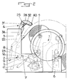
- the device for cutting and applying, without glue, the start of a new strip coil on a mandrel 1 of a reel essentially consists of a first pivoting means 2 for cutting the strip 3 to be wound up and applying the end of the latter on a new mandrel 1, without prior gluing of the latter, and by a second pivoting means 4 for introducing, after cutting, the end of the strip 3 in the first pivoting means 2 and for applying said strip 3 on the new mandrel 1.
- the first pivoting means 2 is constituted by a pivoting frame formed by a pair of arms 5 extending parallel near the edges of the frame 6 of the winding machine, interconnected by a cross member 7 supporting a cross-cut knife 8 and each actuated by a jack 11 and by a first set of parallel elastic belts 9, endless, mounted on at least a pair of parallel shafts 10, guided in rotation, at their ends on the arms 5 ( Figures 1 to 3).
- the parallel elastic belts 9 are preferably mounted on three trees arranged in parallel so as to form in vertical section a triangle, one of whose sides formed by the belts 9 is deformable elastically by application against the mandrel 1 and one of the vertices of which is formed by one of the shafts 10, is movable by pivoting, by means of a pair of arms 12, represented in FIG. 3 by a simple center line. So when pivoting of the arms 5 carrying the shafts 10 with the belts 9 and of the application said belts 9 on the mandrel 1, there is a tension of the belts 9 due to their deformation during winding on the mandrel 1, this tension being compensated by a pivoting of the shaft 10 mounted on the arms 12.
- the elastic belts 9 are loaded in the rest position by a tensioning device preliminary constituted by a roller or a shaft 13 pivotally mounted on the chassis formed by the arms 5 by means of pivoting levers 14, shown in Figure 3 by a center line, said levers being loaded by return springs (not shown), tending to tension the belts 9 between the two fixed shafts 10 in the direction of the new mandrel 1.
- the arms 5 carrying the shafts 10 advantageously have a cutting into a portion of a circle 15 extending between the bearings of the two shafts fixed 10 for supporting the belts 9.
- a passage for the mandrel 1 is released on the arms 5 allowing perfectly the application of the belts on said mandrel 1 without risk of contact of the arms 5 with the ends of the mandrel 1 or with the latter's support hubs.
- teeth 16 are arranged at regular intervals on a shaft 17 extending between the arms 5 near their free end, that is to say near the bearings of the fixed shaft 10 most the exterior with respect to the pivoting arms 5, the ends of said teeth 16 projecting beyond the free ends of the arms 5 and extending pivotally towards the mandrel 1 inwards relative to the cut in a portion of a circle 15, these pivoting teeth 16 being loaded at their other end by springs of return 18 and coming into abutment against stops 19, the return springs and stops being advantageously mounted on crosspieces connecting the arms 5.
- the first pivoting means has beak-shaped elements formed by the teeth 16 and tending to apply intimately the end of the strip to be wound on the chuck 1.
- the cross-cut knife 8 is in the form of a carriage guided on the cross-member 7 and actuated by a jack and cooperates with a transverse anvil 20 also extending between the arms 5, this so-called anvil 20 forming a stop for a similar anvil 21 fixed at the end corresponding to the second pivoting means 4, the cutting plane of the knife 8 preferably being located near the axis of the lower fixed shaft 10 of guide and support of the first set of parallel elastic belts 9 (figure 3).
- the second pivoting means 4 is constituted by two parallel arms upper 22, pivotally mounted on the chassis 6 of the unwinding machine and each actuated at one end by a jack 23, their other end having a hook shape in an arc 24, and by a set 25 of application of the end of the strip on the mandrel 1 extending between the arms 22.
- the assembly 25 for applying the strip end to the mandrel 1 is constituted by a second train of parallel elastic belts 26, without end, mounted on at least two pairs of parallel shafts 27 extending between the arms superiors 22.
- the parallel elastic belts 26 are preferably mounted on three parallel shafts 27 forming a triangle with variable section, one of which sides formed by the belts 26 is elastically deformable by application against the mandrel 1 and one of the vertices of which is formed by one of the shafts 27, is pivotally movable, via a pair of arms 28 (shown by their center line in Figure 3).
- the elastic belts 26 are loaded in the rest position by a tensioning device preliminary consisting of a roller or a shaft 29 pivotally mounted between the upper arms 22 by means of pivoting levers 30, represented by their center line in Figure 3, said levers being loaded by return springs (not shown), tending to tension the belts 26 between the two fixed shafts 27 in the direction of the new mandrel 1.
- the application assembly 25 of the strip end on the mandrel 1 is advantageously mounted, with possibility of movement, between the upper arms 22, by means of two support carriages 31 guided in rails in an arc 32, provided on the corresponding faces of the upper arms 22, by means of rollers 33, one at least said carriages 31 being actuated in displacement by means of a cylinder 34 ( Figure 2).
- This embodiment allows, by application of the assembly 25 on the new mandrel 1, to start the winding of the strip on said new mandrel 1, by movement of the carriages 1 in the position shown in broken line at the end in FIG.
- the second pivoting means 4 is advantageously provided, between the support carriages 31, at regular intervals, with staggered arrangement by relative to the teeth 16, of longitudinal guide claws 35, the end of which facing the teeth 16 moves away from the mandrel 1.
- the shafts 27 of guide of the elastic belts 26 are advantageously constituted by a plurality of short rollers mounted on a rotating guide axis simultaneously forming a support for the longitudinal guide claws 35.
- the rails of guiding in an arc of a circle 32 are advantageously provided, on their turned side outwardly of the arms 22, of a rack 36 meshing with a pinion corresponding 37 guided on the carriage 31, the pinions 37 of the two carriages 31 of support of the assembly 25 being interconnected by a rigid shaft. So it is possible to provide only a single actuator 34 for actuating a carriage 31, the actuation of this single carriage 31 having the effect, by meshing of the pinion 37 corresponding with the rack 36, to rotate corresponding to the pinion 37 of the other carriage 31 and, thus, by meshing with the corresponding rack 36, synchronous drive and displacement of said other carriage 31.
- each arm upper 22 is provided at its free end 24 in the form of a hook with a stop 38 intended to cooperate with an adjustable stop 39 provided on the arms 5 of the first pivoting means 2.
- the contact between these two stops corresponds to the strip cross-sectional position, in which the anvils 20 and 21 tighten said strip for cutting by the knife 8.
- the second pivoting means 4 is provided, between the hook-shaped ends in an arc 24 of the arms 22, of a roller transverse 40 for deflecting the strip to be cut and wound.
- This roll 40 is especially intended to bring the strip to be cut into its position pinching by anvils 20 and 21.
- the device for cutting and applying the start of a strip new coil on a reel mandrel works as follows:
- the operator who has previously mounted a new non-glued mandrel 1, initiates the procedure cutting the strip and applying the end to the new mandrel 1.
- the drive of the full reel is stopped and the first pivoting means 2 is then tilted by means of the jacks 11 in its position shown in the Figure 1, in which the first set of elastic belts 9 is applied in an arc of circle around the mandrel 1 and the second pivoting means 4 is tilted by via the jacks 23, also in the position shown in FIG. 1.
- the strip is deflected by the roller 40 and is brought between the anvils 20 and 21.
- the cutting knife transverse 8 is then actuated, then the assembly 25 is moved by the carriages 31 actuated by the cylinder 34 and moving in synchronism thanks to the pinion 37 meshing with the racks 36 of the guide rails 32, in order to bring the cut end of the strip between the end of the belts 9 and the new chuck 1.
- the progress of the various operations can be controlled by a programmable controller or the like, so the operator only needs to set up the new mandrel and integrate the different parameters winding, namely the length of the wound strip or the reel diameter, etc.
- the strip to be wound is stored in a tape accumulator provided upstream.
- the invention it is possible to make a cut and a perfect application of the start of a strip to be wound on a new mandrel, without bonding, in particular in the case of winding fragile materials.
Description
La présente invention concerne le domaine des machines à enrouler des matières en bande pour la réalisation de bobines et a pour objet un dispositif de coupe et d'application, sans colle, du début de bande d'une nouvelle bobine sur un mandrin d'un enrouleur.The present invention relates to the field of winding machines strip materials for the production of coils and relates to a device cutting and applying, without glue, the strip start of a new reel on a reel mandrel.
L'enroulement de bandes au moyen de machines à enrouler pose généralement le problème, d'une part, de la coupe de la bande et, d'autre part, de l'application correcte de l'extrémité de la bande sur le mandrin après la coupe. A cet effet, il est possible de réaliser la coupe pendant le défilement de la bande suivant un principe appelé coupe à la volée, dans lequel un couteau est projeté dans le parcours de la bande et l'extrémité coupée de la bande est projetée sur un mandrin préalablement encollé ou muni d'une ou de plusieurs bandes adhésives de réception de ladite extrémité, qui est serrée, en outre, sur ledit mandrin par la bande au cours de son enroulement.The winding of strips by means of winding machines poses generally the problem, on the one hand, of the cutting of the strip and, on the other hand, of the correct application of the end of the strip to the mandrel after cutting. AT this effect, it is possible to make the cut while the strip is running following a principle called cutting on the fly, in which a knife is thrown in the path of the strip and the cut end of the strip is projected onto a mandrel pre-glued or fitted with one or more adhesive strips of receiving said end, which is further clamped on said mandrel by the strip during its winding.
Une telle coupe pendant le défilement de la bande permet une production continue, pratiquement sans ralentissement de la vitesse de défilement de la bande lors de la coupe.Such a cut during the running of the strip allows a continuous production, practically without slowing down of the running speed of the strip when cutting.
Toutefois, dans le cas de l'enroulement de bandes en des matières relativement friables, telles que des films de mica, de placage, ou analogue, une coupe à la volée compromet la bonne tenue de l'extrémité coupée qui peut éventuellement être endommagée sur une longueur relativement importante, voire avoir tendance à provoquer une cassure de la bande à une certaine distance de l'endroit de la coupe, ce qui peut entraíner un mauvais enroulement, voire un défaut d'enroulement, la bande n'étant même plus appliquée sur le nouveau mandrin ou présentant un rabat.However, in the case of the winding of strips of materials relatively brittle, such as mica films, plating, or the like, a cutting on the fly compromises the good performance of the cut end which can possibly be damaged over a relatively long length, or even tend to break the tape at a distance from the place of the cut, which can cause poor winding, or even winding fault, the tape not even being applied to the new one mandrel or having a flap.
Il est également connu de réaliser la coupe à l'arrêt, c'est-à-dire la bobine pleine étant arrêtée après enroulement, la bande à enrouler étant alors stockée provisoirement dans un accumulateur disposé en amont de la machine à enrouler.It is also known to make the cut at a standstill, that is to say the full reel being stopped after winding, the strip to be wound then being temporarily stored in an accumulator located upstream of the wrap.
Dans un tel cas la coupe est réalisée manuellement par deux opérateurs, dont l'un tient l'extrémité de la bande coupée pendant que l'autre encolle le nouveau mandrin, puis applique ladite extrémité sur ledit nouveau mandrin, dont le démarrage est commandé par l'un des deux opérateurs. Un tel mode de réalisation nécessite, cependant, une intervention des opérateurs dans une machine en marche, ce qui entraíne forcément un risque d'accident. In such a case the cut is carried out manually by two operators, one of whom holds the end of the cut strip while the other glue the new mandrel, then apply said end to said new mandrel, the start of which is controlled by one of the two operators. Such embodiment requires, however, operator intervention in a machine running, which necessarily entails a risk of accident.
En outre, certaines matières en bande nécessitent un enroulement sur le mandrin de réception sans application de colle ou de ruban adhésif, par simple pincement des premières spires enroulées, ce dans l'optique de leur transformation ultérieure. Un tel enroulement est particulièrement délicat à réaliser, en évitant tout risque de patinage lors du démarrage de l'enroulement dans le cas d'enroulement de matières relativement rigides.In addition, certain strip materials require winding on the receiving mandrel without applying glue or adhesive tape, by simple pinching of the first coiled turns, with a view to their transformation later. Such a winding is particularly difficult to achieve, avoiding any risk of slipping when starting the winding in the case for winding relatively rigid materials.
On connaít également, par GB-A-1 154 662, un dispositif de coupe de bandes et d'enroulement du début de bande sur un nouveau mandrin, dans lequel ledit nouveau mandrin est entouré sur la plus grande partie de sa circonférence par une coquille en deux éléments articulés entre-eux, l'action de coupe de la bande ayant pour effet, dans la poursuite du mouvement du couteau, d'amener le début de bande dans un coin formé à cet effet à la partie correspondante de la coquille.We also know, from GB-A-1 154 662, a cutting device of strips and winding of the start of the strip on a new mandrel, in which said new mandrel is surrounded over most of its circumference by a shell in two elements hinged together, the action of cutting of the strip having the effect, in the pursuit of the movement of the knife, to bring the start of the tape in a corner formed for this purpose to the part corresponding to the shell.
Par ailleurs, ce document GB-A-1 154 662 décrit un premier moyen pivotant entourant partiellement le nouveau mandrin et un deuxième moyen pivotant de réalisation de la coupe de la bande à enrouler. Ce deuxième moyen pivotant consiste, en fait, uniquement en un couteau dentelé, s'étendant sur toute la largeur du moyen pivotant et disposé en extrémité d'une boíte à air sous pression et tendant à réaliser l'introduction du début de bande dans la coquille formée par le premier moyen pivotant, à l'arrivée en fin de course de coupe du couteau, cette introduction étant favorisée par le soufflage d'air. Cependant, du fait d'une coupe suivant une ligne dentelée, en cas d'enroulage d'une matière particulièrement souple, le soufflage d'air combiné à une rotation rapide peut ne présenter une efficacité suffisante pour éviter un repliement des pointes des dents.Furthermore, this document GB-A-1 154 662 describes a first means pivoting partially surrounding the new mandrel and a second means pivot for making the cut of the strip to be wound. This second plea swivel consists, in fact, only of a serrated knife, extending over the entire width of the pivoting means and disposed at the end of a pressurized air box and tending to carry out the introduction of the beginning of the strip into the shell formed by the first pivoting means, upon arrival at the end of the knife cutting stroke, this introduction being favored by air blowing. However, due to a cut along a serrated line, in case of winding of a particularly material flexible, blowing air combined with rapid rotation may not present a sufficient effectiveness to avoid folding of the tips of the teeth.
Par ailleurs, DE-A-39 00560 décrit un dispositif d'enroulage d'un début de bande sur un mandrin, ce dispositif consistant en une paire de griffes pourvues chacune d'un levier articulé de fermeture partielle, lesdites griffes et leurs leviers articulés étant reliés entre-eux par des arbres guidés en rotation, sur lesquels sont montées des courroies parallèles.Furthermore, DE-A-39 00560 describes a device for winding a start of strip on a mandrel, this device consisting of a pair of prongs each provided with an articulated partial closing lever, said claws and their articulated levers being interconnected by shafts guided in rotation, on which are mounted parallel belts.
Ainsi, le dispositif peut être amené à s'étendre partiellement autour du nouveau mandrin, sur lequel doit être enroulée la bande, les courroies étant destinées, d'une part, à appliquer le début de bande sur le nouveau mandrin, et, d'autre part, à le guider autour dudit mandrin jusqu'à réaliser au moins un tour d'enroulement, ce en évitant tout retournement de l'extrémité de bande avant ou pendant l'enroulement de la première spire.Thus, the device can be caused to extend partially around of the new mandrel, on which the strip must be wound, the belts being intended, on the one hand, to apply the start of strip to the new mandrel, and, on the other hand, to guide it around said mandrel until at least one revolution winding, this avoiding any overturning of the front end of the strip or during the winding of the first turn.
Ce dispositif ne prévoit, toutefois, nullement un deuxième moyen destiné à parfaire l'introduction de la bande dans le dispositif, ainsi que son maintien sans pli pendant la réalisation de la première spire. En effet, il n'est prévu aucun moyen mobile tendant à suivre le mouvement de l'extrémité de la bande à enrouler.This device does not, however, provide a second means intended to perfect the introduction of the strip into the device, as well as its hold without crease during the realization of the first turn. Indeed, it is not planned no movable means tending to follow the movement of the end of the strip at wrap.
Enfin, on connaít par US-A-4 326 679 un dispositif de coupe d'une bande et d'application de son extrémité sur un nouveau mandrin, ce dispositif mettant en oeuvre des moyens latéraux d'application de la bande sur une partie importante de la circonférence du nouveau mandrin, ainsi qu'un moyen de coupe de ladite bande.Finally, we know from US-A-4 326 679 a device for cutting a tape and applying its end to a new mandrel, this device using lateral means for applying the strip on a part significant circumference of the new mandrel, as well as a means of cutting of said band.
Ce document ne décrit nullement, en extrémité de l'un des moyens d'application de la bande autour du nouveau mandrin, de moyen transversal de déviation pour la bande à couper et à enrouler. De même, il n'est pas prévu de moyen supplémentaire assurant un surcroít de tension de la bande pendant la coupe, de sorte qu'après ladite coupe survient une tendance à la création d'un mou sur la partie correspondante de la bande, qui a pour conséquence une application aléatoire de l'extrémité de celle-ci sur le nouveau mandrin.This document in no way describes, at the end of one of the means application of the tape around the new mandrel, transverse means of deflection for the strip to be cut and wound. Similarly, there are no plans to additional means ensuring an additional belt tension during the cutting, so that after said cutting occurs a tendency to create a slack on the corresponding part of the strip, which results in an application random end of it on the new mandrel.
La présente invention a pour but de pallier ces inconvénients en proposant un dispositif de coupe et d'application permettant d'entourer un nouveau mandrin sur la plus grande partie de son pourtour afin de favoriser l'enroulement d'un début de bande consécutivement à une coupe de ladite bande, cette coupe étant une coupe droite, franche et non dentelée.The object of the present invention is to overcome these drawbacks by proposing a cutting and application device making it possible to surround a new mandrel over most of its periphery to promote winding of a strip start following a cut of said strip, this cut being a straight cut, frank and not serrated.
Elle a, en effet, pour objet un dispositif de coupe et d'application, sans colle, du début de bande d'une nouvelle bobine sur un mandrin d'un enrouleur, essentiellement constitué par un premier moyen pivotant de coupe de la bande à enrouler et d'application de l'extrémité de cette dernière sur un nouveau mandrin, sans encollage préalable de ce dernier, et par un deuxième moyen pivotant d'introduction, après coupe, de l'extrémité de la bande dans le premier moyen pivotant et d'application de ladite bande sur le nouveau mandrin, le deuxième moyen pivotant comportant un ensemble d'application de l'extrémité de bande sur le mandrin s'étendant entre des bras montés à pivotement sur le châssis de la machine a dérouler, le premier moyen pivotant comporte une traverse de support d'un couteau de coupe transversale se présentant sous forme d'un chariot guidé sur la traverse et actionné par un vérin et coopérant avec une enclume transversale s'étendant également entre des bras formant un châssis pivotant constituant le premier moyen pivotant, cette dite enclume formant une butée pour une enclume analogue fixée à l'extrémité correspondante du deuxième moyen pivotant, le plan de coupe du couteau étant préférentiellement situé à proximité de l'axe d'un arbre fixe inférieur de guidage et de support d'un premier train de courroies élastiques parallèles. It has, in fact, for a cutting and application device, without glue, from the beginning of the strip of a new reel on a mandrel of a reel, essentially constituted by a first pivoting means for cutting the tape to roll up and apply the end of the latter on a new mandrel, without prior gluing of the latter, and by a second means swivel for inserting, after cutting, the end of the strip into the first pivoting means and application of said strip on the new mandrel, the second pivoting means comprising a set for applying the end of strip on the mandrel extending between arms pivotally mounted on the chassis the machine to unroll, the first pivoting means comprises a support crosspiece a cross-cut knife in the form of a carriage guided on the cross member and actuated by a jack and cooperating with a transverse anvil also extending between arms forming a pivoting frame constituting the first pivoting means, said anvil forming a stop for an anvil analog fixed to the corresponding end of the second pivoting means, the plane of cutting the knife being preferably located near the axis of a tree lower guide and support for a first set of elastic belts parallel.
L'invention sera mieux comprise, grâce à la description ci-après, qui
se rapporte à un mode de réalisation préféré, donné à titre d'exemple non limitatif,
et expliqué avec référence aux dessins schématiques annexés, dans lesquels :
Comme le montrent les figures 1 à 3 des dessins annexés, le
dispositif de coupe et d'application, sans colle, du début de bande d'une nouvelle
bobine sur un mandrin 1 d'un enrouleur est essentiellement constitué par un
premier moyen pivotant 2 de coupe de la bande 3 à enrouler et d'application de
l'extrémité de cette dernière sur un nouveau mandrin 1, sans encollage préalable
de ce dernier, et par un deuxième moyen pivotant 4 d'introduction, après coupe, de
l'extrémité de la bande 3 dans le premier moyen pivotant 2 et d'application de
ladite bande 3 sur le nouveau mandrin 1.As shown in Figures 1 to 3 of the accompanying drawings, the
device for cutting and applying, without glue, the start of a new strip
coil on a
Le premier moyen pivotant 2 est constitué par un châssis pivotant
formé par une paire de bras 5 s'étendant parallèlement prés des bords du châssis 6
de la machine à enrouler, reliés entre-eux par une traverse 7 de support d'un
couteau de coupe transversale 8 et actionnés chacun par un vérin 11 et par un
premier train de courroies élastiques parallèles 9, sans fin, montées sur au moins
une paire d'arbres parallèles 10, guidés en rotation, à leurs extrémités sur les bras 5
(figures 1 à 3).The
Les courroies élastiques parallèles 9 sont, de préférence, montées sur
trois arbres disposés parallèlement de manière à former en section verticale un
triangle, dont l'un des côtés formés par les courroies 9 est déformable
élastiquement par application contre le mandrin 1 et dont l'un des sommets, formé
par l'un des arbres 10, est déplaçable par pivotement, par l'intermédiaire d'une
paire de bras 12, représentés sur la figure 3 par un simple trait d'axe. Ainsi, lors du
pivotement des bras 5 portant les arbres 10 avec les courroies 9 et de l'application
desdites courroies 9 sur le mandrin 1, il se produit une tension des courroies 9 due
à leur déformation lors de l'enroulement sur le mandrin 1, cette tension étant
compensée par un pivotement de l'arbre 10 monté sur les bras 12.The parallel
Selon une caractéristique de l'invention, les courroies élastiques
parallèles 9 sont chargées, en position de repos, par un dispositif de tension
préalable constitué par un rouleau ou un arbre 13 monté de manière pivotante sur
le châssis formé par les bras 5 par l'intermédiaire de leviers de pivotement 14,
représentés sur la figure 3 par un trait d'axe, lesdits leviers étant chargés par des
ressorts de rappel (non représentés), tendant à tendre les courroies 9 entre les deux
arbres fixes 10 en direction du nouveau mandrin 1.According to a characteristic of the invention, the
Les bras 5 portant les arbres 10 présentent avantageusement une
découpe en portion de cercle 15 s'étendant entre les paliers des deux arbres
fixes 10 de support des courroies 9. Ainsi, un passage pour le mandrin 1 est
dégagé sur les bras 5 permettant parfaitement l'application des courroies sur ledit
mandrin 1 sans risque de mise en contact des bras 5 avec les extrémités du
mandrin 1 ou avec les moyeux de support de ce dernier.The
Selon une caractéristique de l'invention, des dents 16 sont disposées
à intervalles réguliers sur un arbre 17 s'étendant entre les bras 5 près de leur
extrémité libre, c'est-à-dire à proximité des paliers de l'arbre fixe 10 le plus à
l'extérieur par rapport aux bras pivotants 5, les extrémités desdites dents 16
dépassant les extrémités libres des bras 5 et s'étendant en pivotement vers le
mandrin 1 vers l'intérieur par rapport à la découpe en portion de cercle 15, ces
dents pivotantes 16 étant chargées à leur autre extrémité par des ressorts de
rappel 18 et venant en butée contre des arrêts 19, les ressorts de rappel et les arrêts
étant avantageusement montés sur des traverses reliant les bras 5. Ainsi, le
premier moyen pivotant présente des éléments en forme de bec formés par les
dents 16 et tendant à appliquer intimement l'extrémité de bande à enrouler sur le
mandrin 1.According to a characteristic of the invention,
Le couteau de coupe transversale 8 se présente sous forme d'un
chariot guidé sur la traverse 7 et actionné par un vérin et coopère avec une
enclume transversale 20 s'étendant également entre les bras 5, cette dite
enclume 20 formant une butée pour une enclume analogue 21 fixée à l'extrémité
correspondante du deuxième moyen pivotant 4, le plan de coupe du couteau 8
étant préférentiellement situé à proximité de l'axe de l'arbre fixe 10 inférieur de
guidage et de support du premier train de courroies élastiques parallèles 9
(figure 3).The
Le deuxième moyen pivotant 4 est constitué par deux bras parallèles
supérieurs 22, montés à pivotement sur le châssis 6 de la machine à dérouler et
actionnés chacun, à une extrémité, par un vérin 23, leur autre extrémité présentant
une forme de crochet en arc de cercle 24, et par un ensemble 25 d'application de
l'extrémité de bande sur le mandrin 1 s'étendant entre les bras 22.The second pivoting means 4 is constituted by two parallel arms
upper 22, pivotally mounted on the
L'ensemble 25 d'application de l'extrémité de bande sur le mandrin 1
est constitué par un deuxième train de courroies élastiques parallèles 26, sans fin,
montées sur au moins deux paires d'arbres parallèles 27 s'étendant entre les bras
supérieurs 22.The
Les courroies élastiques parallèles 26 sont, de préférence, montées
sur trois arbres parallèles 27 formant un triangle à section variable, dont l'un des
côtés formés par les courroies 26 est déformable élastiquement par application
contre le mandrin 1 et dont l'un des sommets, formé par l'un des arbres 27, est
déplaçable par pivotement, par l'intermédiaire d'une paire de bras 28 (représentés
par leur trait d'axe sur la figure 3). Par ailleurs, les courroies élastiques
parallèles 26 sont chargées, en position de repos, par un dispositif de tension
préalable constitué par un rouleau ou un arbre 29 monté de manière pivotante
entre les bras supérieurs 22 par l'intermédiaire de leviers de pivotement 30,
représentés par leur trait d'axe sur la figure 3, lesdits leviers étant chargés par des
ressorts de rappel (non représentés), tendant à tendre les courroies 26 entre les
deux arbres fixes 27 en direction du nouveau mandrin 1.The parallel
Selon une autre caractéristique de l'invention, et comme le montre
plus particulièrement la figure 3 des dessins annexés, l'ensemble 25 d'application
de l'extrémité de bande sur le mandrin 1 est avantageusement monté, avec
possibilité de déplacement, entre les bras supérieurs 22, au moyen de deux
chariots de support 31 guidés dans des rails en arc de cercle 32, prévus sur les
faces correspondantes des bras supérieurs 22, par l'intermédiaire de galets 33, l'un
au moins desdits chariots 31 étant actionné en déplacement au moyen d'un
vérin 34 (figure 2). Ce mode de réalisation permet, par application de
l'ensemble 25 sur le nouveau mandrin 1, de débuter l'enroulement de la bande sur
ledit nouveau mandrin 1, par déplacement des chariots 1 dans la position
représentée en trait mixte fin à la figure 3, afin d'effectuer l'insertion du début de
bande entre les courroies élastiques parallèles 9 du premier moyen pivotant 2 et le
nouveau mandrin 1, puis, par un mouvement en arc de cercle de l'ensemble 25 en
sens inverse, d'assurer un enroulement parfait de la première spire par
accompagnement dudit début de bande sur au moins une spire, sans application de
colle sur ledit nouveau mandrin 1.According to another characteristic of the invention, and as shown
more particularly FIG. 3 of the accompanying drawings, the
Afin de garantir un passage parfait du début de bande de la sortie du
premier moyen pivotant 2, et en particulier des dents pivotantes 16, vers
l'ensemble 25, le deuxième moyen pivotant 4 est avantageusement pourvu, entre
les chariots supports 31, à intervalles réguliers, avec disposition en quinconce par
rapport aux dents 16, de griffes longitudinales de guidage 35, dont l'extrémité
tournée vers les dents 16 s'écarte du mandrin 1. A cet effet, les arbres 27 de
guidage des courroies élastiques 26 sont avantageusement constitués par une
pluralité de galets de faible longueur montés sur un axe de guidage en rotation
formant simultanément un support pour les griffes longitudinales de guidage 35.
Par l'application, au début de l'enroulement de l'extrémité de la bande sur le
nouveau mandrin 1, ces griffes 35 sont insérées entre les dents 16 et assurent la
continuité du passage et de l'application de ladite extrémité de bande sur ledit
mandrin 1.In order to guarantee a perfect passage from the beginning of the strip to the exit of the
first pivoting means 2, and in
Conformément à une autre caractéristique de l'invention, les rails de
guidage en arc de cercle 32 sont avantageusement munis, sur leur face tournée
vers l'extérieur des bras 22, d'une crémaillère 36 engrenant avec un pignon
correspondant 37 guidé sur le chariot 31, les pignons 37 des deux chariots 31 de
support de l'ensemble 25 étant reliés entre eux par un arbre rigide. Ainsi, il est
possible de ne prévoir qu'un seul vérin 34 d'actionnement d'un chariot 31,
l'actionnement de ce seul chariot 31 ayant pour effet, par engrènement du
pignon 37 correspondant avec la crémaillère 36, d'entraíner une rotation
correspondante du pignon 37 de l'autre chariot 31 et, ainsi, par engrènement avec
la crémaillère 36 correspondante, un entraínement et un déplacement synchrones
dudit autre chariot 31.According to another characteristic of the invention, the rails of
guiding in an arc of a
Selon une autre caractéristique de l'invention, chaque bras
supérieur 22 est pourvu à son extrémité libre 24 en forme de crochet d'une
butée 38 destinée à coopérer avec une butée réglable 39 prévue sur les bras 5 du
premier moyen pivotant 2. Le contact entre ces deux butées correspond à la
position de coupe transversale de la bande, dans laquelle les enclumes 20 et 21
serrent ladite bande en vue de la coupe par le couteau 8.According to another characteristic of the invention, each arm
upper 22 is provided at its
Par ailleurs, le deuxième moyen pivotant 4 est pourvu, entre les
extrémités en forme de crochet en arc de cercle 24 des bras 22, d'un rouleau
transversal 40 de déviation de la bande à couper et à enrouler. Ce rouleau 40 est
tout particulièrement destiné à amener la bande à couper dans sa position de
pincement par les enclumes 20 et 21.Furthermore, the second pivoting means 4 is provided, between the
hook-shaped ends in an
Le dispositif de coupe et d'application du début de bande d'une nouvelle bobine sur un mandrin d'un enrouleur fonctionne de la manière suivante :The device for cutting and applying the start of a strip new coil on a reel mandrel works as follows:
Dès qu'une bobine à enrouler est pleine, l'opérateur, qui a
préalablement monté un nouveau mandrin 1 non encollé, déclenche la procédure
de coupe de la bande et d'application de l'extrémité sur le nouveau mandrin 1.
L'entraínement de la bobine pleine est arrêté et le premier moyen pivotant 2 est
alors basculé par l'intermédiaire des vérins 11 dans sa position représentée à la
figure 1, dans laquelle le premier train de courroies élastiques 9 s'applique en arc
de cercle autour du mandrin 1 et le deuxième moyen pivotant 4 est basculé par
l'intermédiaire des vérins 23, également dans la position représentée à la figure 1.
Par ce basculement du deuxième moyen pivotant 4, la bande est déviée par le
rouleau 40 et est amenée entre les enclumes 20 et 21. Le couteau de coupe
transversale 8 est alors actionné, puis l'ensemble 25 est déplacé par les chariots 31
actionnés par le vérin 34 et se déplaçant en synchronisme grâce au pignon 37
engrenant avec les crémaillères 36 des rails de guidage 32, afin d'amener
l'extrémité coupée de la bande entre l'extrémité des courroies 9 et le nouveau
mandrin 1.As soon as a reel to be wound is full, the operator, who has
previously mounted a new
L'entraínement de ce dernier est alors déclenché et l'ensemble 25 est
déplacé en sens inverse, de manière à amener les griffes longitudinales de guidage
entre les dents 16 et d'assurer une continuité de l'application de la bande sur le
mandrin 1. Cette application avec pression par l'intermédiaire des courroies 9 et 26
assure un entraínement de la bande par le mandrin 1 sans collage de l'extrémité de
bande. Après enroulement de quelques spires, les moyens pivotants 2 et 4 sont
actionnés dans le sens d'un retour vers leur position de repos représentée à la
figure 2 et l'enroulement de la nouvelle bobine est poursuivi de manière habituelle.The training of the latter is then triggered and the
Le déroulement des différentes opérations peut être contrôlé par un automate programmable ou analogue, de sorte que l'opérateur n'a besoin que de mettre en place le nouveau mandrin et d'intégrer les différents paramètres d'enroulement, à savoir la longueur de bande enroulée ou le diamètre de bobine, etc. De manière connue, pendant l'opération de coupe, la bande à enrouler est stockée dans un accumulateur de bande prévu en amont.The progress of the various operations can be controlled by a programmable controller or the like, so the operator only needs to set up the new mandrel and integrate the different parameters winding, namely the length of the wound strip or the reel diameter, etc. In known manner, during the cutting operation, the strip to be wound is stored in a tape accumulator provided upstream.
Grâce à l'invention, il est possible de réaliser une coupe et une application parfaite d'un début de bande à enrouler sur un nouveau mandrin, sans collage, en particulier dans le cas d'enroulement de matières fragiles.Thanks to the invention, it is possible to make a cut and a perfect application of the start of a strip to be wound on a new mandrel, without bonding, in particular in the case of winding fragile materials.
Bien entendu, l'invention n'est pas limitée au mode de réalisation décrit et représente aux dessins annexés. Des modifications restent possibles, notamment du point de vue de la constitution des divers éléments ou par substitution d'équivalents techniques, sans sortir pour autant du domaine de protection de l'invention.Of course, the invention is not limited to the embodiment describes and shows in the accompanying drawings. Modifications are still possible, in particular from the point of view of the constitution of the various elements or by substitution of technical equivalents, without departing from the scope of protection of the invention.
Claims (12)
- Device for the cutting and gluelessly applying the web leading end for a new web roll onto the core (1) of a winder, essentially consisting of a first pivoting means (2) of cutting the strip (3) to be coiled and of application of the end of the latter onto a new core (1), without prior gluing of the latter, and of a second pivoting means (4) of introduction, after cutting, of the end of the strip (3) into the first pivoting means (2) for the application of the said strip (3) onto the new core (1), characterised by the fact that the first pivoting means (2) includes a cross-bar (7) supporting transverse cutting blade (8) presented in the form of a carrier guided along the cross-bar (7), operated by an actuator and working in conjunction with a transverse anvil (20) also extending between arms (5) forming a pivoting frame to constitute the first pivoting means (2), the said anvil (20) forming a stop for a similar anvil (21) fixed to the corresponding end of the second pivoting means (4), the cutting plane of the blade (8) preferably being situated close to the axis of a fixed lower shaft (10) for the guidance and support of a first set of parallel elastic belts (9), the second pivoting means (4) including an assembly (25) for the application of the end of the strip onto the core (1) extending between arms (22) mounted in pivoting fashion on the frame (6) of the decoiling machine.
- Device according to claim 1, characterised by the fact that the parallel elastic belts (9) are preferably mounted on three shafts arranged in parallel in such a way as to form a triangle in vertical section, one of whose sides formed by the belts (9) is elastically deformable by being pressed against the core (1) and one of whose tops, formed by one of the shafts (10), can be moved by a pivoting action, by means of a pair of arms (12), and that they are loaded, in the rest position, by a pre-tensioning device consisting of a roll or a shaft (13) mounted in pivoting fashion on the frame formed by the arms (5) by means of pivoting levers (14), the said levers being loaded by return springs tending to pull the belts (9) between the two fixed shafts (10) in the direction of the new core (1).
- Device according to either of claims 1 or 2, characterised by the fact that teeth (16) are positioned at regular intervals on a shaft (17) extending between the arms (5) close to their free end, in other words close to the bearings of the fixed shaft (10) which are furthest out in relation to the pivoting arms (5), the ends of the said teeth (16) overlapping the free ends of the arms (5), and extending in pivoting fashion towards the core (1) and inwards in relation to the circular arc cut (15), these pivoting teeth (16) being loaded at their other end by return springs (18) and pressing against stops (19), the return springs and the stops being mounted on cross-bars connecting the arms (5).
- Device according to claim 1, characterised by the fact that the assembly (25) for the application of the end of the strip onto the core (1) is mounted, with the possibility of movement, between the upper arms (22) by means of two supporting carriers (31) guided along rails in the arc of a circle (32) provided on the corresponding faces of the upper arms (22), by means of rollers (33), at least one of the said carriers (31) having its movement operated by an actuator (34).
- Device according to either of claims 1 or 4, characterised by the fact that the assembly (25) for the application of the end of the strip onto the core (1) consists of a second set of parallel endless elastic belts (26), mounted on at least two parallel shafts (27) extending between the upper arms (22) and guided on the supporting carriers (31).
- Device according to either of claims 4 or 5, characterised by the fact that the parallel elastic belts (26) are mounted on three parallel shafts (27) forming a triangle of variable section, one of whose sides formed by the belts (26) is elastically deformable by being pressed against the core (1), and one of whose tops, formed by one of the shafts (27), can be moved by pivoting, by means of a pair of arms (28).
- Device according to either of claims 5 or 6, characterised by the fact that the parallel elastic belts (26) are loaded, in the rest position, by a pre-tensioning device consisting of a roll or a shaft (29) mounted in pivoting fashion between the upper arms (22) by means of pivoting levers (30), the said levers being loaded by return springs tending to pull the belts (26) between the two fixed shafts (27) in the direction of the new core (1).
- Device according to any of claims 1 and 3 to 5, characterised by the fact that, in order to guarantee a perfect passage of he start of the belt from the exit of the first pivoting means (2), and in particular from the pivoting teeth (16) towards the assembly (25), and that the second pivoting means (4) are provided, between the supporting carriers (31), at regular intervals, in a staggered arrangement in relation [to the] supports (31), at regular intervals, in a staggered arrangement in relation to the pivoting teeth (16), with longitudinal guidance claws (35), of which the end turned towards the pivoting teeth (16) points away from the core (1).
- Device according to claim 8, characterised by the fact that the guide shafts (27) of the elastic belts (26) consist of a number of short rollers mounted on a rotating guide spindle which simultaneously forms a support for the longitudinal guidance claws (35).
- Device according to claim 4, characterised by the fact that the circular arc guide rails (32) are provided, on their side facing the outside of the arms (22), with a rack (36) engaging with a corresponding pinion (37) guided along the carrier (31), the pinions (37) of the two carriers (31) which support the assembly (25) being connected to each other by a rigid shaft.
- Device according to any of claims 1, 4, 5 or 7, characterised by the fact that each upper arm (22) is provided at its hook-shaped free end (24), with a stop (38) designed to work in conjunction with an adjustable stop (39) provided on the arms (5) of the first pivoting means (2).
- Device according to any of claims 1, 3 to 5, 7 or 10, characterised by the fact that the second pivoting means (4) are provided, between the circular arc hook-shaped ends (24) of the arms (22), with a transverse roll (40) for deflection of the strip to be cut and to be coiled.
Applications Claiming Priority (2)
| Application Number | Priority Date | Filing Date | Title |
|---|---|---|---|
| FR9409880A FR2723361B1 (en) | 1994-08-05 | 1994-08-05 | DEVICE FOR CUTTING AND APPLYING, WITHOUT ADHESIVE, THE BEGINNING OF THE BAND OF A NEW REEL ON A CHUCK OF A REEL |
| FR9409880 | 1994-08-05 |
Publications (2)
| Publication Number | Publication Date |
|---|---|
| EP0699610A1 EP0699610A1 (en) | 1996-03-06 |
| EP0699610B1 true EP0699610B1 (en) | 1998-11-18 |
Family
ID=9466215
Family Applications (1)
| Application Number | Title | Priority Date | Filing Date |
|---|---|---|---|
| EP19950440044 Expired - Lifetime EP0699610B1 (en) | 1994-08-05 | 1995-07-12 | Device for cutting and gluelessly applying the web leading end for a new web roll onto the core of a winder |
Country Status (3)
| Country | Link |
|---|---|
| EP (1) | EP0699610B1 (en) |
| DE (1) | DE69506060T2 (en) |
| FR (1) | FR2723361B1 (en) |
Families Citing this family (5)
| Publication number | Priority date | Publication date | Assignee | Title |
|---|---|---|---|---|
| DE19502769C2 (en) * | 1995-01-30 | 1997-04-03 | Kampf Gmbh & Co Maschf | Device for the adhesive-free application of webs in a winding machine, preferably a multiple winding machine |
| DE10342213A1 (en) * | 2003-09-12 | 2005-04-07 | Voith Paper Patent Gmbh | Method for winding a moving material web and winding machine for carrying out the method |
| CN102514962B (en) * | 2012-01-06 | 2014-11-05 | 广东达诚机械有限公司 | Coil replacing mechanism |
| FR3068341B1 (en) * | 2017-07-03 | 2021-05-14 | Spoolex | DEVICE AND METHOD FOR WINDING AND TRANSFERRING A STRIP FROM A FULL COIL TO AN EMPTY COIL |
| CN107934024B (en) * | 2017-10-27 | 2023-08-29 | 华美节能科技集团有限公司 | Flexible plate packaging machine |
Family Cites Families (9)
| Publication number | Priority date | Publication date | Assignee | Title |
|---|---|---|---|---|
| GB1154662A (en) * | 1967-02-02 | 1969-06-11 | Agfa Gevaert Nv | Web Winding Apparatus. |
| US3614010A (en) * | 1969-09-03 | 1971-10-19 | Eddystone Machinery Co | Cloth winder having cutter and pressure bar |
| US3633840A (en) * | 1970-03-02 | 1972-01-11 | Eddystone Machinery Co | Winding sheet material with threading device |
| BE792966A (en) * | 1971-12-30 | 1973-06-19 | Agfa Gevaert Nv | TWO-STAGE TAPE WRAPPER |
| US3908924A (en) * | 1973-05-16 | 1975-09-30 | Greene Gmbh & Co Kg Maschbau | Winding machines |
| CH567999A5 (en) * | 1973-06-15 | 1975-10-15 | Oerlikon Buehrle Ag | Winding machine cutting device - has guide attached to knife blade able to cut web against sleeve |
| US4326679A (en) * | 1980-07-02 | 1982-04-27 | The Black Clawson Company | Method and apparatus for roll changing on a winder device |
| JPS59167441A (en) * | 1983-03-10 | 1984-09-20 | Fujikura Ltd | Device for sticking double-sided adhesive sheet to wind-up cylinder |
| DE3900560A1 (en) * | 1989-01-11 | 1990-07-12 | Maier Christian Masch | Apparatus for the winding of fabric webs |
-
1994
- 1994-08-05 FR FR9409880A patent/FR2723361B1/en not_active Expired - Lifetime
-
1995
- 1995-07-12 EP EP19950440044 patent/EP0699610B1/en not_active Expired - Lifetime
- 1995-07-12 DE DE1995606060 patent/DE69506060T2/en not_active Expired - Fee Related
Also Published As
| Publication number | Publication date |
|---|---|
| DE69506060D1 (en) | 1998-12-24 |
| DE69506060T2 (en) | 1999-06-17 |
| EP0699610A1 (en) | 1996-03-06 |
| FR2723361A1 (en) | 1996-02-09 |
| FR2723361B1 (en) | 1996-10-31 |
Similar Documents
| Publication | Publication Date | Title |
|---|---|---|
| EP3248920B1 (en) | Method for cutting and connecting two strips end-to-end, halted in an unwinding machine, cutting and connection device and machine provided with such a device allowing said method to be carried out | |
| EP0475886B1 (en) | Method and means for opening a paper roll and for splicing the end of a paper ribbon to the end of a second paper ribbon | |
| FR2623176A1 (en) | APPARATUS AND METHOD FOR TREATING THE END PART OF A ROLLED PAPER SHEET ARRANGED AT A CONNECTION LOCATION | |
| EP0419299A2 (en) | Film unwinding carriage for a packaging machine | |
| FR2617123A1 (en) | TAPE WITH LONGITUDINAL REINFORCEMENT, PACKAGING METHOD AND PACKAGE COMPRISING SUCH A TAPE, INSTALLATION AND MACHINE FOR IMPLEMENTING THE PACKING METHOD, AND DEVICE FOR MAKING SUCH A TAPE | |
| FR2617800A1 (en) | BAND LOADING APPARATUS FOR A PACKING MACHINE | |
| FR2619557A1 (en) | OUTPUT DEVICE FOR STRIP TEXTILE | |
| FR2476044A1 (en) | DISCONNECT DEVICE FOR BANDS ROLLED ON CHUCKS MOUNTED ON ROTATION DRIVEN ROLLERS | |
| EP0699610B1 (en) | Device for cutting and gluelessly applying the web leading end for a new web roll onto the core of a winder | |
| FR2477513A1 (en) | DEVIATOR DEVICE FOR PAPER BANDS IN PARTICULAR | |
| EP2112106B1 (en) | Method and device for cutting and gluing end-to-end for an unrolling machine | |
| FR2528023A1 (en) | PROCESS AND DEVICE FOR THE RECOVERY OF FLAT PRODUCTS PRESENTING IN SCALE PROVISIONS, PARTICULARLY FOR THE RECOVERY OF PRINTED SHEETS | |
| EP0795504B1 (en) | Continuous unwinder for bobbins with at least one means for simultaneously unwinding of two bobbins in twin or co-axial arrangement | |
| EP3087020B1 (en) | Method for joining together the ends of two hot-melt items in the form of strips or plies, and end-joining module for implementing said method | |
| EP0921074B1 (en) | Method and apparatus for collecting aligned articles by means of adhesive tapes | |
| FR2933898A1 (en) | METHOD OF FORMING ANGULAR SECTION PROFILES AND DEVICE FOR IMPLEMENTING SAID METHOD | |
| EP1008152B1 (en) | Wiring harness wrapping | |
| FR2586663A1 (en) | DEVICE FOR FEEDING AND CUTTING A BAND OF LABELS | |
| EP2730527B1 (en) | Unwinding device provided with a web lifting system | |
| EP0619255B1 (en) | Device for cutting and attaching the leading end of a web of a new roll onto a core of a winder | |
| WO1993014622A1 (en) | Device for tying vine or other trainable plants | |
| EP0363295B1 (en) | Device for cutting and uniting a moving web on a mandrel in continuous-winding machines | |
| FR2679541A1 (en) | Device for end-to-end bonding and cutting, for an unrolling machine | |
| EP0820930B1 (en) | Machine for strapping rolls of web material | |
| FR2815936A1 (en) | DEVICE FOR BOTTLING PRODUCTS, ESPECIALLY A ROD, BY MEANS OF AN ADHESIVE TAPE |
Legal Events
| Date | Code | Title | Description |
|---|---|---|---|
| PUAI | Public reference made under article 153(3) epc to a published international application that has entered the european phase |
Free format text: ORIGINAL CODE: 0009012 |
|
| AK | Designated contracting states |
Kind code of ref document: A1 Designated state(s): CH DE GB IT LI NL |
|
| 17P | Request for examination filed |
Effective date: 19960722 |
|
| GRAG | Despatch of communication of intention to grant |
Free format text: ORIGINAL CODE: EPIDOS AGRA |
|
| GRAG | Despatch of communication of intention to grant |
Free format text: ORIGINAL CODE: EPIDOS AGRA |
|
| 17Q | First examination report despatched |
Effective date: 19980319 |
|
| GRAG | Despatch of communication of intention to grant |
Free format text: ORIGINAL CODE: EPIDOS AGRA |
|
| GRAH | Despatch of communication of intention to grant a patent |
Free format text: ORIGINAL CODE: EPIDOS IGRA |
|
| GRAH | Despatch of communication of intention to grant a patent |
Free format text: ORIGINAL CODE: EPIDOS IGRA |
|
| GRAA | (expected) grant |
Free format text: ORIGINAL CODE: 0009210 |
|
| AK | Designated contracting states |
Kind code of ref document: B1 Designated state(s): CH DE GB IT LI NL |
|
| REG | Reference to a national code |
Ref country code: CH Ref legal event code: EP |
|
| REG | Reference to a national code |
Ref country code: CH Ref legal event code: NV Representative=s name: WERNER FENNER PATENTANWALT |
|
| REF | Corresponds to: |
Ref document number: 69506060 Country of ref document: DE Date of ref document: 19981224 |
|
| GBT | Gb: translation of ep patent filed (gb section 77(6)(a)/1977) |
Effective date: 19981210 |
|
| ITF | It: translation for a ep patent filed |
Owner name: STUDIO TORTA S.R.L. |
|
| PGFP | Annual fee paid to national office [announced via postgrant information from national office to epo] |
Ref country code: GB Payment date: 19990707 Year of fee payment: 5 |
|
| PLBE | No opposition filed within time limit |
Free format text: ORIGINAL CODE: 0009261 |
|
| STAA | Information on the status of an ep patent application or granted ep patent |
Free format text: STATUS: NO OPPOSITION FILED WITHIN TIME LIMIT |
|
| PGFP | Annual fee paid to national office [announced via postgrant information from national office to epo] |
Ref country code: CH Payment date: 19991027 Year of fee payment: 5 |
|
| 26N | No opposition filed | ||
| PGFP | Annual fee paid to national office [announced via postgrant information from national office to epo] |
Ref country code: DE Payment date: 20000318 Year of fee payment: 5 |
|
| PG25 | Lapsed in a contracting state [announced via postgrant information from national office to epo] |
Ref country code: DE Free format text: LAPSE BECAUSE OF NON-PAYMENT OF DUE FEES Effective date: 20000503 |
|
| PG25 | Lapsed in a contracting state [announced via postgrant information from national office to epo] |
Ref country code: GB Free format text: LAPSE BECAUSE OF NON-PAYMENT OF DUE FEES Effective date: 20000712 |
|
| PG25 | Lapsed in a contracting state [announced via postgrant information from national office to epo] |
Ref country code: LI Free format text: LAPSE BECAUSE OF NON-PAYMENT OF DUE FEES Effective date: 20000731 Ref country code: CH Free format text: LAPSE BECAUSE OF NON-PAYMENT OF DUE FEES Effective date: 20000731 |
|
| PGFP | Annual fee paid to national office [announced via postgrant information from national office to epo] |
Ref country code: NL Payment date: 20000731 Year of fee payment: 6 |
|
| GBPC | Gb: european patent ceased through non-payment of renewal fee |
Effective date: 20000712 |
|
| REG | Reference to a national code |
Ref country code: CH Ref legal event code: PL |
|
| PG25 | Lapsed in a contracting state [announced via postgrant information from national office to epo] |
Ref country code: NL Free format text: LAPSE BECAUSE OF NON-PAYMENT OF DUE FEES Effective date: 20020201 |
|
| NLV4 | Nl: lapsed or anulled due to non-payment of the annual fee |
Effective date: 20020201 |
|
| PG25 | Lapsed in a contracting state [announced via postgrant information from national office to epo] |
Ref country code: IT Free format text: LAPSE BECAUSE OF NON-PAYMENT OF DUE FEES Effective date: 20050712 |