EP0697829B1 - Schälvorrichtung - Google Patents
Schälvorrichtung Download PDFInfo
- Publication number
- EP0697829B1 EP0697829B1 EP95911278A EP95911278A EP0697829B1 EP 0697829 B1 EP0697829 B1 EP 0697829B1 EP 95911278 A EP95911278 A EP 95911278A EP 95911278 A EP95911278 A EP 95911278A EP 0697829 B1 EP0697829 B1 EP 0697829B1
- Authority
- EP
- European Patent Office
- Prior art keywords
- knife
- housing
- peeling
- peeling device
- container
- Prior art date
- Legal status (The legal status is an assumption and is not a legal conclusion. Google has not performed a legal analysis and makes no representation as to the accuracy of the status listed.)
- Expired - Lifetime
Links
Images
Classifications
-
- A—HUMAN NECESSITIES
- A23—FOODS OR FOODSTUFFS; TREATMENT THEREOF, NOT COVERED BY OTHER CLASSES
- A23N—MACHINES OR APPARATUS FOR TREATING HARVESTED FRUIT, VEGETABLES OR FLOWER BULBS IN BULK, NOT OTHERWISE PROVIDED FOR; PEELING VEGETABLES OR FRUIT IN BULK; APPARATUS FOR PREPARING ANIMAL FEEDING- STUFFS
- A23N7/00—Peeling vegetables or fruit
- A23N7/02—Peeling potatoes, apples or similarly shaped vegetables or fruit
- A23N7/023—Peeling potatoes, apples or similarly shaped vegetables or fruit one by one
-
- A—HUMAN NECESSITIES
- A47—FURNITURE; DOMESTIC ARTICLES OR APPLIANCES; COFFEE MILLS; SPICE MILLS; SUCTION CLEANERS IN GENERAL
- A47J—KITCHEN EQUIPMENT; COFFEE MILLS; SPICE MILLS; APPARATUS FOR MAKING BEVERAGES
- A47J17/00—Household peeling, stringing, or paring implements or machines
- A47J17/14—Machines for peeling
-
- Y—GENERAL TAGGING OF NEW TECHNOLOGICAL DEVELOPMENTS; GENERAL TAGGING OF CROSS-SECTIONAL TECHNOLOGIES SPANNING OVER SEVERAL SECTIONS OF THE IPC; TECHNICAL SUBJECTS COVERED BY FORMER USPC CROSS-REFERENCE ART COLLECTIONS [XRACs] AND DIGESTS
- Y10—TECHNICAL SUBJECTS COVERED BY FORMER USPC
- Y10T—TECHNICAL SUBJECTS COVERED BY FORMER US CLASSIFICATION
- Y10T83/00—Cutting
- Y10T83/202—With product handling means
- Y10T83/2092—Means to move, guide, or permit free fall or flight of product
- Y10T83/22—Means to move product laterally
- Y10T83/2205—Reciprocating means
Definitions
- the invention relates to a peeling device for fruit, with one with his knife edge along the one to be peeled Surface of the fruit movable peeling knife, being the peeling knife on a preferably by means of a electric drive unit in vibrations offset swing arm is arranged (see e.g. GB-A-2 244 208).
- fruit here means food understood, the surface of which is processed by peeling can, especially vegetables such as beets, carrots, horseradish, Potatoes, turnips, asparagus and the like, and fruits such as apples, Pears, tropical fruits and the like
- the present invention has as its object to create a peeling device by means of a Drive unit is drivable and the simpler Handling enables quick peeling of the fruit.
- the invention proposes that the swing arm below a support surface is intended for the fruit to be peeled, and that the Peeling knife a knife opening in the support surface penetrates, with the knife edge over the support surface protrudes.
- the Peeling knife vibrated by the swing arm.
- the swing arm is preferably driven here electrical, the structure of the drive unit similar that of an electric shaver with one Swinging head can be formed or with one rotating electric motor and an eccentric drive. It is but also possible to use a different drive unit, For example, a water-powered turbine with a Hose can be connected to the water pipe, which is advantageous, for example, if none electrical energy is available.
- the fruit to be peeled by hand over the support surface moves through the support surface protruding knife edge a surface treatment this fruit, with which part of this surface is removed, i.e. a peeling process takes place. It is only necessary to successively peel the fruit to be peeled different positions over the support surface move until this fruit is completely peeled.
- the support surface formed from the surface of a lid of a container is preferably in the one or more recesses are provided for the passage of the trays.
- This The container forms a stable foot for the one hand Support surface, in which the below this support surface located swing arm is added, and further takes when processing the fruit using the peeling knife emerging trays, which are then emptied by Container can be easily removed.
- the knife edge at one certain position of the fruit on the support surface largest possible area of the surface of this fruit in According to one, being able to peel an operation
- the support surface in the area the knife opening a curved and / or at least two planes enclosing an angle formed surface and it's the knife edge adapted to this shape of the support surface.
- the distance can be used for this purpose the knife edge can be adjustable from the support surface. The larger this distance, the larger it is Shell thickness.
- swing arm with the Drive unit is detachably connected. This is not just a simple cleaning of the swing arm with it arranged peeling knife allows without that Drive unit comes into contact with the water what especially dangerous with electric drive units and is therefore inadmissible, but it will also be the optional Use of swing arms with different shapes Allows peeling knives in a simple way.
- the drive unit is preferably in a side on the container, preferably pivotable about an axis or removable, fixed housing arranged, in which Side wall of the container has a passage opening for the Swing arm is provided. This way it becomes a safe one
- the drive unit is housed outside the container possible, although the required attachment of the Swing arm with the peeling knife below the support surface is guaranteed.
- the fact that the housing in which Drive unit is housed, swiveling or is removably attached to the side wall of the container, is not only in the storage of the invention Device reduces the space requirement, but also that Cleaning the container with water allows without the drive unit comes into contact with this water.
- the Containers from a lower part and a housing for the upper part of the drive unit. They collect through the recess in the lower part of the container in the container lid into the inside of the container and this bottom part of the container can be easily removed and, for example, can also be cleaned in a dishwasher.
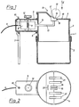
- the peeling device has a container 1 on the bottom of a container 2, one with this secured against rotation, but removable Container upper part 3 and from a non-rotatable with this connected, but removable cover 4.
- a housing 5 is provided on the side, either pivotable about an axis 6 with the container top 3 is connected or removable on the upper part of the container 3 is attached.
- This housing 5 is also on his end protruding from the upper container part 3 via a support foot 7 supported, which either swivels or is removably connected to the housing 5.
- Inside the Housing 5 is an electric drive unit 8, which has a vibrating head similar to an electric one Has razor.
- the power supply to the electrical Drive unit 8 is carried out by a cable 9.
- the housing 5 also has a switch 10 for switching on and off of the electric drive unit.
- the altitude of the electric drive unit 8 in Housing 5 can via a worm drive 11 by means of a Knurled screw 12 provided on the outside of the housing can be set.
- a swing arm 13 can be removed with the swing head connected, the through a passage opening 14 in Container upper part 3 protrudes into this and on his angled end carries a paring knife 15 which by a knife opening 16 protrudes through the cover 4 and its Knife edge 17 which is a support surface for the one to be peeled Fruit-forming surface 18 of lid 4 protrudes.
- this surface can also be curved be.
- the knife edge 17 has one of the surface 18 adapted shape. Doing this in one operation peeling a larger area of usually one fruit having a circular cross section.
- a fruit for example a carrot, whose Cross section in Fig. 1 by a dashed circle 19th is indicated to be peeled, where will it be manually in Direction of arrow 20 in Fig. 2 over the knife edge 17 of the peeling knife 15, whereby by the vibrations of the knife a surface treatment and thus a This fruit is peeled.
- the thickness of the shells is determined by the amount by which the knife edge 17 protrudes over the surface 18 of the lid.
- the bowls fall through recesses 21 into the lower container part 2, which can be emptied after lifting off the upper part 3.
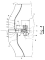
- a housing 22 for example can be made of plastic.
- a first chamber 23 in which the drive unit 8 is housed and in which by a partition 24 the swing arm 13 protrudes.
- the chamber 23 is through another partition 25 separated from a stand 40.
- a further chamber 26 is created by the partition 24 in the housing 22 in which the cutting tool is arranged is.
- This chamber has an opening 27 through which Shells and other waste can fall out.
- the partition wall 24 extends through a support member 28, which carries a knife guide 29.
- the knife guide 29 has a guide surface 30 which is curved in a circular arc is and forms a kind of guide for the knife 17.
- the knife has a curved arc Knife foot 31, which rests on the guide surface 30. over two webs 33 and 34 is the knife edge 17 in Distance to the knife base 31 kept, creating a space 32 formed between the cutting edge 17 and the knife base 31 becomes. Through this space 32 slide from the Knife edge 17 cut trays through and then fall laterally on the support member 28 and the Knife guide 29 over the opening 27 out of the chamber 26 out.
- a driver arm 35 is attached to the knife base 31 or integrally connected to this, this knife arm is oriented essentially vertically downwards, being the extension of its axis through the center of the circle 38 goes.
- This circle center 38 is the common one Center of the circular segments of the knife edge 17, the Knife foot 31 and the guide surface 30.
- the swing arm 13 At the end of Guide arm 35 is the swing arm 13 via a Hinge pin 36 hinged. Now the swing arm 13 in a substantially along its axis, back and forth movement offset, so the knife slides back and forth on the guide surface 30 and performs one Swinging motion along an arc. The middle-point this circular arc is also the center 38 of the circle.
- the knife guide 29 an elongated hole 37.
- the mechanical drive of the swing arm 13 can be via a Swing armature drive take place. But it is also possible to design the drive unit as a rotatable electric motor and the swing arm 13 via an eccentric drive to connect with this motor 8. Of course also the other drive options mentioned above given.
- the housing has an opening accessible from above, in which the knife is stored.
- the knife edge 17 stands at least from one side, as more precisely is explained in connection with Fig. 4, via this opening out.
- the extent of this protrusion can be determined by a Adjusting device, e.g. changed a worm gear by at least the entire cutting unit with the support member 28, the knife guide 29 and the knife can be moved vertically. It is useful if the motor 8 is also moved, which is the case here Case is given by the fact that the engine with the Support member 28 is connected.
- the aforementioned foot 40 is connected to a floor 41, the Has support feet 42 for resting on a table.
- the two Chambers 23 and 26, the foot 40 and the bottom 41 form one C-shaped frame, in the space between this C, i.e. between the chamber 26 and the bottom 41 Collection container 43 can be inserted, the below the opening 27 and the cut trays catches.
- the Chambers 23 and 26 completely separated from each other, see above that also cleaning the cutting tool with water is unproblematic and in particular no water in the Chamber 23 can penetrate.
- the housing forms a trough 39 in the area of the knife, in which the fruit to be peeled.
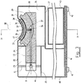
- Fig. 4 shows a partial sectional view along the line IV-IV of FIG. 3. It can be seen in particular from FIG. 4 that that the knife 17, 31 not only on the guide surface 30th is led but also against moving into Cutting direction is supported on the knife guide 29.
- the knife guide 29 accordingly has an L-shaped Cross-section.
- the arm 35 extends into an opening the knife guide. He is articulated with the hinge pin 36 hinged to the swing arm 13.
- Next is in the 4 to see better how the Knife edge 17 opposite the top of the housing is staggered.
- the top of the case is in the direction of movement of the fruit in front of the knife edge 17 offset from this, so that between the housing top 46 and the knife edge 17 a gap 32 arises.
- a small gap 50 available between the Knife edge 17 and the housing wall a small gap 50 available. By moving the knife vertically the cutting gap can be adjusted.
- This work surface can be flat throughout. she can but also a bit towards the top of the case be raised, as by the two sloping slopes 48 and 49 is indicated.
- the trough 39 in which the to processing fruit is carried out in the direction of movement the fruit a bump (46, 47) where the peel is cut off and then falls off again.
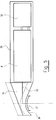
- FIG. 5 shows a further exemplary embodiment of the invention, where the peeling device as a hand-held device is trained.
- This device has a housing 53 in which arranged the drive motor 8 and a battery 52 are.
- This housing can be cylindrical and so designed that it can be easily carried in the hand.
- a cutting head 51 contains the actual cutting device with the knife edge 17 and the swing arm 13, which with the drive motor 18 is coupled.
- the cutter head 51 can against the Housing 53 are moved as shown by the dashed line Lines indicated. This adjusts the depth of cut. Otherwise, the drive and guidance of the knife corresponding to the exemplary embodiments of FIGS. 1 to 4, so that the relevant details in FIG. 5 are omitted.
- the knife 17 also can be straight and only a linear movement carries out.
- two movement options are possible, namely one Movement where the knife is parallel to its cutting edge 17 is moved back and forth or a second movement, at which moves it back and forth perpendicular to its knife edge becomes.
Landscapes
- Engineering & Computer Science (AREA)
- Food Science & Technology (AREA)
- Life Sciences & Earth Sciences (AREA)
- Chemical & Material Sciences (AREA)
- Polymers & Plastics (AREA)
- Apparatuses For Bulk Treatment Of Fruits And Vegetables And Apparatuses For Preparing Feeds (AREA)
- Control And Other Processes For Unpacking Of Materials (AREA)
- Electrical Discharge Machining, Electrochemical Machining, And Combined Machining (AREA)
Description
- Fig. 1
- einen schematischen Schnitt durch eine Schälvorrichtung nach einem ersten Ausführungsbeispiel der Erfindung;
- Fig. 2
- eine Draufsicht auf die Schälvorrichtung der Fig. 1 gesehen in Richtung des Pfeiles II in Fig. 1;
- Fig. 3
- eine schematische Schnittansicht einer Schälvorrichtung nach einem zweiten Ausführungsbeispiel der Erfindung;
- Fig. 4
- einen Schnitt längs der Linie IV-IV der Fig. 3; und
- Fig. 5
- eine schematische Seitenansicht einer Schälvorrichtung nach einem dritten Ausführungsbeispiel der Erfindung.
Claims (15)
- Schälvorrichtung für Früchte, mit einem mit seiner Messerschneide (17) entlang einer zu schälenden Oberfläche der Frucht (19) bewegbaren Schälmesser (15), wobei das schälmesser (15) mit einem mittels eines Antriebsaggregates (8) in Schwingung versetzten Schwingarm (13) verbunden ist, dadurch gekennzeichnet, daß der Schwingarm (13) unterhalb einer Abstützfläche (18) für die zu schälende Frucht (19) vorgesehen ist und daß das Schälmesser (15) eine Messeröffnung (16, 50) in der Abstützfläche (18, 46) durchsetzt, wobei die Messerschneide (17) über die Abstützfläche (18, 46) vorsteht.
- Schälvorrichtung nach Anspruch 1, dadurch gekennzeichnet, daß der Schwingarm (13) das Schälmesser (15) in einer Richtung parallel zur Messerschneide (17) hin- und herbewegt.
- Schälvorrichtung nach Anspruch 1 oder 2, dadurch gekennzeichnet, daß das Schälmesser kreissegmentförmig gebogen ist und an einer kreissegmentförmig gebogenen Führungsfläche (30) einer Messerführung (29) längs einer Kreisbahn hin- und herbeweglich geführt ist.
- Schälvorrichtung nach Anspruch 3, dadurch gekennzeichnet, daß das Schälmesser (15) einen mit der Führungsbahn (30) der Messerführung in Berührung stehenden Messerfuß (31) aufweist und daß die Messerschneide (17) durch Stege (33, 34) im Abstand zu dem Messerfuß (31) gehalten ist, wobei zwischen der Messerschneide (17) und dem Messerfuß (31) ein Zwischenraum (32) gebildet ist.
- Schälvorrichtung nach Anspruch 4, dadurch gekennzeichnet, daß die Messerführung (29) im Querschnitt L-förmig ausgebildet ist und daß der Messerfuß (31) an beiden schenkeln dieses L abgestützt ist.
- Schälvorrichtung nach einem der Ansprüche 1 bis 5, dadurch gekennzeichnet, daß die Abstützfläche (18, 46) im Bereich der Messeröffnung (16, 50) eine gekrümmte (39) und/oder auszumindest zwei miteinander einen Winkel einschließenden Ebenen gebildete Oberfläche aufweist und das die Messerschneide (17) dieser Form der Abstütztfläche angepaßt ist.
- Schälvorrichtung nach Anspruch 6, dadurch gekennzeichnet, daß die Messerschneide (17) einstellbar gegenüber der Abstützfläche (18, 46) versetzt angeordnet ist, derart, daß die Messerschneide (17) über die Abstützfläche (18, 46) herausragt.
- Schälvorrichtung nach einem der Ansprüche 1 bis 7, dadurch gekennzeichnet, daß das Schälmesser (15) und die Messerführung (29) in einer Kammer (26) eines Gehäuses angeordnet sind und daß diese Kammer (26) eine unterhalb des Schälmessers (15) angeordnete Öffnung (27) aufweist, durch welche abgeschnittene Schalen herausfallen können.
- Schälvorrichtung nach Anspruch 8, dadurch gekennzeichnet, daß das Gehäuse in der Seitenansicht C-förmig ist und daß die Kammer (26) und ein Boden (41) so über einen Ständer (40) miteinander verbunden sind, daß zwischen den Boden (41) und die Kammer (26) ein Auffangbehälter (43) einsetzbar ist.
- Schälvorrichtung nach einem der Ansprüche 1 bis 9, dadurch gekennzeichnet, daß der Schwingarm (13) mit dem Antriebsaggregat (8) lösbar verbunden ist.
- Schälvorrichtung nach einem der Ansprüche 1 bis 10, dadurch gekennzeichnet, daß das Antriebsaggregat (8) in einem seitlich am Behälter (1), vorzugsweise um eine Achse (6) schwenkbar oder entfernbar, befestigten Gehäuse (5) angeordnet ist und daß in der Seitenwand des Behälters (1) eine Durchtrittsöffnung (14) für den Schwingarm (13) vorgesehen ist.
- Schälvorrichtung nach einem der Ansprüche 1 bis 11, dadurch gekennzeichnet, daß das Antriebsaggregat (8) im Gehäuse (5), beispielsweise durch einen mittels einer an der Gehäuseaußenseite angeordneten Rändelschraube (12) betätigbaren Schneckentrieb (11), höhenverstellbar angeordnet ist.
- Schälvorrichtung nach einem der Ansprüche 1 bis 12, dadurch gekennzeichnet, daß der Behälter (1) aus einem Behälterunterteil (2) und einem das Gehäuse (5) für das Antriebsaggregat (8) aufweisenden Behälteroberteil (3) besteht.
- Schälvorrichtung nach einem der Ansprüche 1 bis 13, dadurch gekennzeichnet, daß das Gehäuse (5) an seinem vom Behälter (1) abstehenden Ende mit einem, vorzugsweise schwenkbar oder abnehmbar am Gehäuse (5) befestigten, Stützfuß (7) versehen ist.
- Schälvorrichtung nach einem der Ansprüche 1 bis 4, dadurch gekennzeichnet, daß sie als Handgerät mit einem im wesentlichen zylindrisischen Gehäuse (53) ausgebildet ist und einem Messerkopf (51), der gegenüber dem Gehäuse (53) verschiebbar ist, wobei die Messerschneide und der Schwingarm mit dem Gehäuse (53) verbunden sind.
Applications Claiming Priority (3)
| Application Number | Priority Date | Filing Date | Title |
|---|---|---|---|
| AT557/94 | 1994-03-15 | ||
| AT55794A AT400290B (de) | 1994-03-15 | 1994-03-15 | Schälvorrichtung |
| PCT/EP1995/000743 WO1995024850A1 (de) | 1994-03-15 | 1995-03-01 | Schälvorrichtung |
Publications (2)
| Publication Number | Publication Date |
|---|---|
| EP0697829A1 EP0697829A1 (de) | 1996-02-28 |
| EP0697829B1 true EP0697829B1 (de) | 1998-12-02 |
Family
ID=3493767
Family Applications (1)
| Application Number | Title | Priority Date | Filing Date |
|---|---|---|---|
| EP95911278A Expired - Lifetime EP0697829B1 (de) | 1994-03-15 | 1995-03-01 | Schälvorrichtung |
Country Status (6)
| Country | Link |
|---|---|
| US (1) | US5666877A (de) |
| EP (1) | EP0697829B1 (de) |
| AT (2) | AT400290B (de) |
| DE (1) | DE59504394D1 (de) |
| ES (1) | ES2128045T3 (de) |
| WO (1) | WO1995024850A1 (de) |
Families Citing this family (9)
| Publication number | Priority date | Publication date | Assignee | Title |
|---|---|---|---|---|
| MXPA01005194A (es) * | 2001-05-24 | 2002-11-29 | Cesar Chavira Lopez Carlos | Aparato manual para el pelado de vegetales planos semiconcavos y semiconvexos. |
| NO329703B1 (no) * | 2009-02-24 | 2010-12-06 | John Kristian Haukas | Anordning ved potetskrellemaskin |
| CN107198256B (zh) * | 2016-03-18 | 2023-02-24 | 海南大学 | 一种椰子剥衣机 |
| CN108041625B (zh) * | 2017-12-22 | 2024-02-13 | 郑州治世长云科技有限公司 | 茎秆旋转切削机构及旋切装置 |
| CN109619607A (zh) * | 2018-12-26 | 2019-04-16 | 安徽省怡果生态科技有限公司 | 一种猕猴桃榨汁一体机中的切割去皮机构 |
| CN109730327A (zh) * | 2018-12-26 | 2019-05-10 | 安徽省怡果生态科技有限公司 | 一种猕猴桃榨汁一体机 |
| CN112772942B (zh) * | 2021-02-22 | 2022-01-04 | 安徽南朋工业设计有限公司 | 应用于茯苓深加工的自动去皮组件 |
| CN113068988B (zh) * | 2021-03-31 | 2022-08-30 | 广东美的厨房电器制造有限公司 | 食材处理设备 |
| CN114403465A (zh) * | 2022-01-18 | 2022-04-29 | 金华职业技术学院 | 一种橘子榨汁用内捣式橘皮分离装置 |
Family Cites Families (7)
| Publication number | Priority date | Publication date | Assignee | Title |
|---|---|---|---|---|
| DE1288257B (de) * | 1967-02-01 | 1969-01-30 | Frank Edgar | Schaelgeraet |
| DE2258126A1 (de) * | 1972-11-28 | 1974-05-30 | Schill Maja Masch | Speckschneidemaschine od.dgl. mit zugwalze und messerhalter |
| JPS5553360Y2 (de) * | 1975-07-22 | 1980-12-10 | ||
| FR2616057B1 (fr) * | 1987-06-05 | 1990-12-07 | Cailliot Serge | Appareil d'epluchage de fruits et legumes |
| GB9011520D0 (en) * | 1990-05-23 | 1990-07-11 | Ng Cheung Ming | Peeler |
| CN2126005U (zh) * | 1992-06-22 | 1992-12-30 | 勇士电胡刀工业有限公司 | 蔬果皮切削器 |
| DE9415688U1 (de) * | 1994-09-28 | 1994-11-17 | Krause Georg | Vorrichtung zum kontinuierlichen Abschneiden der an Tierkörperteilstücken anhaftenden Fettschichten |
-
1994
- 1994-03-15 AT AT55794A patent/AT400290B/de not_active IP Right Cessation
-
1995
- 1995-03-01 AT AT95911278T patent/ATE173898T1/de not_active IP Right Cessation
- 1995-03-01 DE DE59504394T patent/DE59504394D1/de not_active Expired - Fee Related
- 1995-03-01 WO PCT/EP1995/000743 patent/WO1995024850A1/de active IP Right Grant
- 1995-03-01 US US08/549,730 patent/US5666877A/en not_active Expired - Fee Related
- 1995-03-01 EP EP95911278A patent/EP0697829B1/de not_active Expired - Lifetime
- 1995-03-01 ES ES95911278T patent/ES2128045T3/es not_active Expired - Lifetime
Also Published As
| Publication number | Publication date |
|---|---|
| ES2128045T3 (es) | 1999-05-01 |
| US5666877A (en) | 1997-09-16 |
| AT400290B (de) | 1995-11-27 |
| ATE173898T1 (de) | 1998-12-15 |
| EP0697829A1 (de) | 1996-02-28 |
| DE59504394D1 (de) | 1999-01-14 |
| WO1995024850A1 (de) | 1995-09-21 |
| ATA55794A (de) | 1995-04-15 |
Similar Documents
| Publication | Publication Date | Title |
|---|---|---|
| DE19839704C2 (de) | Knoblauchschneider | |
| DE3700601C2 (de) | ||
| DE2727358C3 (de) | Schneidvorrichtung für Gemüse oder andere Lebensmittel | |
| EP0271689A1 (de) | Gerät zum Schneiden von Pilzen in Scheiben | |
| EP0697829B1 (de) | Schälvorrichtung | |
| DE102009035511A1 (de) | Küchengerät | |
| EP1829655A1 (de) | Vorrichtung zum Schneiden von Obst und Gemüse, insbesondere Zwiebeln | |
| DE3413531A1 (de) | Vorrichtung zur verarbeitung von nahrungsmitteln | |
| EP0717599A1 (de) | Vorrichtung zum schälen von stangenförmigem gemüse | |
| DE102018212162B4 (de) | Zufuhreinrichtung für eine Saftpresse, Küchenmaschine und Saftpresse mit Zufuhreinrichtung | |
| DE817351C (de) | Geraet zum Zerteilen von Obst, Kartoffeln und anderen Fruechten | |
| DE19727177A1 (de) | Frucht-Schneidgerät | |
| DE4400144A1 (de) | Elektrisches Schälgerät | |
| EP0039924B1 (de) | Gerät zum Knetmischen plastischer Massen | |
| DE846151C (de) | Verfahren und Geraet zum Zerkleinern von Zwiebeln | |
| DE2644912A1 (de) | Obst- und gemuesezerkleinerungsgeraet | |
| LU100198B1 (de) | Scheibenschneider | |
| DE3642704A1 (de) | Schneidvorrichtung fuer lebensmittel | |
| DE646163C (de) | Selbsttaetige Buerstenbeschneide- und -ausputzmaschine | |
| DE819450C (de) | Zerkleinerungsmaschine fuer Nahrungsmittel | |
| DE19718080A1 (de) | Vorrichtung zum Köpfen und/oder Schwänzen von Fischen | |
| DE2530269C2 (de) | Fleischbearbeitungsmaschine | |
| DE7835535U1 (de) | Haushaltsschaelmaschine fuer eine schaelhaut aufweisende fruechte | |
| DE409566C (de) | Brotschneidemaschine | |
| DE6608205U (de) | Lebensmittelschneidegeraet. |
Legal Events
| Date | Code | Title | Description |
|---|---|---|---|
| PUAI | Public reference made under article 153(3) epc to a published international application that has entered the european phase |
Free format text: ORIGINAL CODE: 0009012 |
|
| 17P | Request for examination filed |
Effective date: 19951109 |
|
| AK | Designated contracting states |
Kind code of ref document: A1 Designated state(s): AT CH DE ES FR GB IT LI PT |
|
| GRAG | Despatch of communication of intention to grant |
Free format text: ORIGINAL CODE: EPIDOS AGRA |
|
| 17Q | First examination report despatched |
Effective date: 19971117 |
|
| GRAG | Despatch of communication of intention to grant |
Free format text: ORIGINAL CODE: EPIDOS AGRA |
|
| GRAH | Despatch of communication of intention to grant a patent |
Free format text: ORIGINAL CODE: EPIDOS IGRA |
|
| GRAH | Despatch of communication of intention to grant a patent |
Free format text: ORIGINAL CODE: EPIDOS IGRA |
|
| GRAA | (expected) grant |
Free format text: ORIGINAL CODE: 0009210 |
|
| AK | Designated contracting states |
Kind code of ref document: B1 Designated state(s): AT CH DE ES FR GB IT LI PT |
|
| REF | Corresponds to: |
Ref document number: 173898 Country of ref document: AT Date of ref document: 19981215 Kind code of ref document: T |
|
| REG | Reference to a national code |
Ref country code: CH Ref legal event code: EP |
|
| REF | Corresponds to: |
Ref document number: 59504394 Country of ref document: DE Date of ref document: 19990114 |
|
| ITF | It: translation for a ep patent filed |
Owner name: DE DOMINICIS & MAYER S.R.L. |
|
| GBT | Gb: translation of ep patent filed (gb section 77(6)(a)/1977) |
Effective date: 19990304 |
|
| ET | Fr: translation filed | ||
| REG | Reference to a national code |
Ref country code: ES Ref legal event code: FG2A Ref document number: 2128045 Country of ref document: ES Kind code of ref document: T3 |
|
| REG | Reference to a national code |
Ref country code: PT Ref legal event code: SC4A Free format text: AVAILABILITY OF NATIONAL TRANSLATION Effective date: 19990301 |
|
| PLBE | No opposition filed within time limit |
Free format text: ORIGINAL CODE: 0009261 |
|
| STAA | Information on the status of an ep patent application or granted ep patent |
Free format text: STATUS: NO OPPOSITION FILED WITHIN TIME LIMIT |
|
| 26N | No opposition filed | ||
| REG | Reference to a national code |
Ref country code: GB Ref legal event code: IF02 |
|
| PGFP | Annual fee paid to national office [announced via postgrant information from national office to epo] |
Ref country code: DE Payment date: 20020328 Year of fee payment: 8 |
|
| PGFP | Annual fee paid to national office [announced via postgrant information from national office to epo] |
Ref country code: FR Payment date: 20020416 Year of fee payment: 8 |
|
| PGFP | Annual fee paid to national office [announced via postgrant information from national office to epo] |
Ref country code: AT Payment date: 20020419 Year of fee payment: 8 |
|
| PGFP | Annual fee paid to national office [announced via postgrant information from national office to epo] |
Ref country code: CH Payment date: 20020422 Year of fee payment: 8 |
|
| PGFP | Annual fee paid to national office [announced via postgrant information from national office to epo] |
Ref country code: ES Payment date: 20020424 Year of fee payment: 8 |
|
| PGFP | Annual fee paid to national office [announced via postgrant information from national office to epo] |
Ref country code: GB Payment date: 20030210 Year of fee payment: 9 |
|
| PGFP | Annual fee paid to national office [announced via postgrant information from national office to epo] |
Ref country code: PT Payment date: 20030228 Year of fee payment: 9 |
|
| PG25 | Lapsed in a contracting state [announced via postgrant information from national office to epo] |
Ref country code: AT Free format text: LAPSE BECAUSE OF NON-PAYMENT OF DUE FEES Effective date: 20030301 |
|
| PG25 | Lapsed in a contracting state [announced via postgrant information from national office to epo] |
Ref country code: ES Free format text: LAPSE BECAUSE OF NON-PAYMENT OF DUE FEES Effective date: 20030303 |
|
| PG25 | Lapsed in a contracting state [announced via postgrant information from national office to epo] |
Ref country code: LI Free format text: LAPSE BECAUSE OF NON-PAYMENT OF DUE FEES Effective date: 20030331 Ref country code: CH Free format text: LAPSE BECAUSE OF NON-PAYMENT OF DUE FEES Effective date: 20030331 |
|
| PG25 | Lapsed in a contracting state [announced via postgrant information from national office to epo] |
Ref country code: DE Free format text: LAPSE BECAUSE OF NON-PAYMENT OF DUE FEES Effective date: 20031001 |
|
| REG | Reference to a national code |
Ref country code: CH Ref legal event code: PL |
|
| PG25 | Lapsed in a contracting state [announced via postgrant information from national office to epo] |
Ref country code: FR Free format text: LAPSE BECAUSE OF NON-PAYMENT OF DUE FEES Effective date: 20031127 |
|
| REG | Reference to a national code |
Ref country code: FR Ref legal event code: ST |
|
| PG25 | Lapsed in a contracting state [announced via postgrant information from national office to epo] |
Ref country code: GB Free format text: LAPSE BECAUSE OF NON-PAYMENT OF DUE FEES Effective date: 20040301 |
|
| REG | Reference to a national code |
Ref country code: ES Ref legal event code: FD2A Effective date: 20030303 |
|
| PG25 | Lapsed in a contracting state [announced via postgrant information from national office to epo] |
Ref country code: PT Free format text: LAPSE BECAUSE OF NON-PAYMENT OF DUE FEES Effective date: 20041015 |
|
| GBPC | Gb: european patent ceased through non-payment of renewal fee | ||
| REG | Reference to a national code |
Ref country code: PT Ref legal event code: MM4A Free format text: LAPSE DUE TO NON-PAYMENT OF FEES Effective date: 20040930 |
|
| PG25 | Lapsed in a contracting state [announced via postgrant information from national office to epo] |
Ref country code: IT Free format text: LAPSE BECAUSE OF NON-PAYMENT OF DUE FEES Effective date: 20050301 |
|
| PG25 | Lapsed in a contracting state [announced via postgrant information from national office to epo] |
Ref country code: PT Free format text: LAPSE BECAUSE OF NON-PAYMENT OF DUE FEES Effective date: 20040301 |