EP0697692A2 - Appareil à cassette à bande magnétique avec dispositif d'entraînement - Google Patents
Appareil à cassette à bande magnétique avec dispositif d'entraînement Download PDFInfo
- Publication number
- EP0697692A2 EP0697692A2 EP95201962A EP95201962A EP0697692A2 EP 0697692 A2 EP0697692 A2 EP 0697692A2 EP 95201962 A EP95201962 A EP 95201962A EP 95201962 A EP95201962 A EP 95201962A EP 0697692 A2 EP0697692 A2 EP 0697692A2
- Authority
- EP
- European Patent Office
- Prior art keywords
- cassette
- cassette holder
- magnetic tape
- holder
- hook
- Prior art date
- Legal status (The legal status is an assumption and is not a legal conclusion. Google has not performed a legal analysis and makes no representation as to the accuracy of the status listed.)
- Withdrawn
Links
- 238000003780 insertion Methods 0.000 claims description 21
- 230000037431 insertion Effects 0.000 claims description 21
- 238000004804 winding Methods 0.000 claims description 20
- 239000002184 metal Substances 0.000 claims description 9
- 230000000881 depressing effect Effects 0.000 claims description 2
- 230000005489 elastic deformation Effects 0.000 description 2
- 230000008878 coupling Effects 0.000 description 1
- 238000010168 coupling process Methods 0.000 description 1
- 238000005859 coupling reaction Methods 0.000 description 1
- 238000006073 displacement reaction Methods 0.000 description 1
- 239000000463 material Substances 0.000 description 1
Images


Classifications
-
- G—PHYSICS
- G11—INFORMATION STORAGE
- G11B—INFORMATION STORAGE BASED ON RELATIVE MOVEMENT BETWEEN RECORD CARRIER AND TRANSDUCER
- G11B15/00—Driving, starting or stopping record carriers of filamentary or web form; Driving both such record carriers and heads; Guiding such record carriers or containers therefor; Control thereof; Control of operating function
- G11B15/675—Guiding containers, e.g. loading, ejecting cassettes
- G11B15/67544—Guiding containers, e.g. loading, ejecting cassettes with movement of the cassette parallel to its main side and subsequent movement perpendicular thereto, i.e. front loading
- G11B15/67555—Guiding containers, e.g. loading, ejecting cassettes with movement of the cassette parallel to its main side and subsequent movement perpendicular thereto, i.e. front loading the second movement only being made by the cassette holder
Definitions
- the invention relates to a magnetic tape cassette device with a drive, which has a loading mechanism for magnetic tape cassettes, which have winding holes in the outer walls for magnetic tape windings provided in the cassettes with winding cores, through which both winding mandrels of the drive and a hook of a cassette holder, which in the insertion direction in one Wall of a cassette lift is guided, are insertable, the cassette holder hook in the ejection position of the drive when inserting a cassette falls into the front access opening when inserted and remains in the latter until the cassette is lowered into the playing position or is pulled out of the drive.
- a drive for magnetic tape cassette devices is known from DE 88 05 726.7 U1 (PHD 88-084).
- the loading mechanism of the drive has a U-shaped cassette shaft, which consists of an upper and a lower cover plate, which are connected on one long side via a transverse wall, which connects the cover plates to one another at a distance corresponding to the cassette height. The distance between the cover plates is held so that a magnetic tape cassette can be moved between the cover walls with slight play.
- the cassette shaft is articulated to a cassette lift that can be rotated around storage points in the chassis. When the cassette lift is turned in the lowering direction, the cassette shaft is also lowered (play position).
- the cassette lift there is a longitudinal slot running in the direction of insertion of the magnetic tape cassette, in which a slide piece of a cassette holder is guided.
- This has a hook-shaped part that in one Access opening of a magnetic tape cassette can occur.
- the slide has a pin which engages in an eject lever which can transfer the cassette from an eject position to a lower position above the playing position.
- the cassette holder will first slide onto the upper wall of the cassette, whereby it deforms elastically. Then, in the so-called ejection position, it falls into the access opening located at the front in the insertion direction, the elastic deformation being eliminated. If the cassette is not pushed in far enough, the cassette holder remains with its hook on the upper wall of the cassette, as a result of which the entire cassette holder is plastically deformed as a result of the deformation forces which may then last for days.
- the cassette holder can tilt in its guide in the vertical direction without deformation and the force required for extending the cassette by means of the cassette holder comes from a metal spring acting on the cassette holder, which is shaped so that the depressing the cassette holder Force after a short travel of the cassette holder in the cassette insertion direction no longer acts on the cassette holder, and allows it to slide almost without force onto the upper cassette wall, a lock acting only in this intermediate position causing the cassette holder to be pushed in only after the Cassette holder hook has fallen into the winding hole of the cassette.
- the cassette holder Due to the tiltable mounting of the cassette holder, it can pivot almost without deformation when a cassette is inserted into the cassette slot. However, this means that the deformation force of the cassette holder cannot be used to hold the magnetic tape cassette in place when it is ejected.
- the force required to hold the magnetic tape cassette when extended is exerted by a metal spring acting on the cassette holder. At its end, this is formed in two height levels and can act on the cassette holder with an upper tip and with a lower tip. If the cassette is pressed against the cassette holder during insertion, the cassette holder swivels, is pushed back a little and slides onto the upper cassette wall.
- the cassette holder hook slides from the lower tip to the upper tip from the metal spring and this only acts on the cassette holder with a reduced force. If the cassette is pushed in further, the cassette holder hook falls into the winding hole of the magnetic tape cassette, the cassette holder hook slides from the upper tip to the lower tip of the metal spring and the metal spring acts on the cassette holder with its full holding force.
- the spring is part of the cassette shaft or cassette lift. This is worked out from the already existing material and is not an additional part that has to be attached or manufactured in some way.
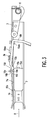
- FIG. 1 shows a cassette lift 3 articulated on the chassis 1 of a drive for a magnetic tape cassette device.
- the drive is designed in particular for use in a motor vehicle.
- the cassette lift 3 is articulated to the chassis 1 by means of bearing eyes 6.
- a cassette shaft 7 is suspended from the cassette lift 3 by means of hinges (not shown) with hinge counterparts 3a of the cassette lift 3. It consists of an upper cover plate 7a, on which a cassette holder spring 16 is attached.
- Another cover plate 7b is arranged parallel to the cover plate 7a below this.
- the two cover plates 7a, 7b are connected at the rear edges by means of a transverse wall 7c.
- a slot 9 extends in the cassette lift 3.
- a cassette holder 10 is displaceably guided in this slot 9.
- the guide is a central piece 10a with a front support 10aa arranged at the top and a rear lower support 10ab.
- a cassette holder hook 10b extends from the central piece 10a within the slot 9.
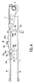
- This has a V-shaped or hook-shaped shape and can, as FIG. 4 shows particularly clearly, in a winding opening 15a of the cassette 15 intervention.
- a metal spring 16 acts on the cassette holder hook 10b. This metal spring 16 is formed at the end acting on the cassette holder hook 10b in two height levels. It has an upper tip 16a and a lower tip 16c, which are connected by an inclined wall 16b.
- a bracket 10c is provided in the slot 9, which also engages the central piece 10a and carries a pin 10d.
- the boom 10c also engages freely in the slot 9.
- the pin 10d passes through a groove 11a of an ejection lever 11.
- This ejection lever 11 is rotatable about a mandrel 12 fixed to the chassis 1.
- the ejection lever 11 brings the loading mechanism into a position above the playing position and in the opposite direction out of the playing position and out again into the extended position when pivoting in the clockwise direction.
- the extension position is shown in FIGS. 1 and 4.
- the ejection position is the position of the cassette holder hook 10b and the ejection lever 11 in which the cassette holder hook 10b falls into the foremost access opening 15a when a magnetic tape cassette is inserted by hand (FIG. 4). From there, when the magnetic tape cassette is inserted further, the cassette holder hook 10b is shifted in the insertion direction 8, taking the ejection lever 11 with it and pivoting it so that the insertion movement is first taken over by a mechanical feed and the cassette slot is moved into the playing position via this mechanical feed becomes.
- FIG. 2 shows the loading device in a side view with the magnetic tape cassette 15 in a position shortly before the first contact with the cassette holder 7.
- the narrow side 15b of the cassette 15 lying in front in the direction of insertion just abuts with its upper edge 15c against the insertion bevel 10e of the cassette holder hook 10b .
- the cassette holder spring 16 presses with its lower tip 16c against the cassette holder 10 from above and largely prevents the cassette holder 10 from being deflected upward.
- the assembly is brought into the position shown in FIG. 3.
- FIG. 3 shows the loading device in a side view with the magnetic tape cassette 15 in a position in which the cassette holder 10 and the magnetic tape cassette 15 are slightly displaced in the insertion direction 8 and the cassette holder hook 10b is just sliding onto the magnetic tape cassette 15.
- the cassette holder 10 is displaced relative to the cassette holder spring 16 so far that its supporting wall 10f has slid on the inclined wall 16b of the cassette holder spring 16.
- the cassette holder spring 16 now presses with its upper tip 16a against the cassette holder 10. Because now acts on the cassette holder 10 and not the lower tip 16c, the force acting on the cassette holder 10 has been significantly reduced.
- FIG. 4 shows a side view of the loading device with the cassette holder hook 10b that has fallen into the winding hole 15a.
- the ejection lever 11 which was previously pivoted slightly against spring force in the insertion direction by the coupling to the cassette holder 10 via the bolt 10d, can pivot back as soon as the cassette holder hook 10b falls into the winding hole 15a, whereby the cassette holder 10 under the lower tip 16c of the cassette holder spring 16 tilts back and dips into the winding hole 15a of the magnetic tape cassette 15.
- This position is identical to the position which the mechanism assumes when the magnetic tape cassette 15 is ejected from the playback position.
Landscapes
- Automatic Tape Cassette Changers (AREA)
Applications Claiming Priority (2)
| Application Number | Priority Date | Filing Date | Title |
|---|---|---|---|
| DE4426510 | 1994-07-27 | ||
| DE4426510A DE4426510A1 (de) | 1994-07-27 | 1994-07-27 | Magnetbandkassettengerät mit einem Laufwerk |
Publications (2)
| Publication Number | Publication Date |
|---|---|
| EP0697692A2 true EP0697692A2 (fr) | 1996-02-21 |
| EP0697692A3 EP0697692A3 (fr) | 1997-12-29 |
Family
ID=6524209
Family Applications (1)
| Application Number | Title | Priority Date | Filing Date |
|---|---|---|---|
| EP95201962A Withdrawn EP0697692A3 (fr) | 1994-07-27 | 1995-07-17 | Appareil à cassette à bande magnétique avec dispositif d'entraínement |
Country Status (4)
| Country | Link |
|---|---|
| US (1) | US5647549A (fr) |
| EP (1) | EP0697692A3 (fr) |
| JP (1) | JPH0845151A (fr) |
| DE (1) | DE4426510A1 (fr) |
Families Citing this family (1)
| Publication number | Priority date | Publication date | Assignee | Title |
|---|---|---|---|---|
| JP2011150761A (ja) * | 2010-01-22 | 2011-08-04 | Fujitsu Ltd | ライブラリ装置 |
Citations (1)
| Publication number | Priority date | Publication date | Assignee | Title |
|---|---|---|---|---|
| DE8805726U1 (de) | 1988-04-30 | 1988-06-23 | Philips Patentverwaltung Gmbh, 2000 Hamburg | Magnetbandkassettengerät |
Family Cites Families (12)
| Publication number | Priority date | Publication date | Assignee | Title |
|---|---|---|---|---|
| FR2020175A1 (fr) * | 1968-10-09 | 1970-07-10 | Autovox Spa | |
| US3669456A (en) * | 1969-02-21 | 1972-06-13 | Beltek Corp | Cassette mounting and dismounting device |
| JPS5931796B2 (ja) * | 1975-12-26 | 1984-08-04 | 株式会社日立製作所 | ラジオジユシンキツキジキキロクサイセイソウチ |
| JPS5888856A (ja) * | 1981-11-20 | 1983-05-27 | Hitachi Ltd | カセツトテ−プレコ−ダのカセツト装着装置 |
| AT374950B (de) * | 1982-06-11 | 1984-06-12 | Philips Nv | Aufzeichnungs- und/oder wiedergabegeraet |
| JPS6085454A (ja) * | 1983-10-14 | 1985-05-14 | Teac Co | カセツト型磁気テ−プ装置 |
| JPS60111537U (ja) * | 1983-12-28 | 1985-07-29 | アルパイン株式会社 | カセツト式テ−プレコ−ダ |
| US5231553A (en) * | 1989-12-18 | 1993-07-27 | U.S. Philips Corporation | System comprising magnetic tape cassette apparatus and two different types of magnetic tape cassettes playable in such apparatus |
| JPH05159426A (ja) * | 1991-12-10 | 1993-06-25 | Matsushita Electric Ind Co Ltd | テープレコーダ |
| JPH05182290A (ja) * | 1991-12-27 | 1993-07-23 | Matsushita Electric Ind Co Ltd | テープ種類検出装置 |
| DE9214519U1 (de) * | 1992-10-27 | 1993-02-25 | Philips Patentverwaltung Gmbh, 2000 Hamburg | Laufwerk in einem elektromechanischen Informationsgerät |
| EP0603439A1 (fr) * | 1992-12-24 | 1994-06-29 | Matsushita Electric Industrial Co., Ltd. | Enregistreur à bande magnétique |
-
1994
- 1994-07-27 DE DE4426510A patent/DE4426510A1/de not_active Withdrawn
-
1995
- 1995-07-17 EP EP95201962A patent/EP0697692A3/fr not_active Withdrawn
- 1995-07-21 US US08/505,413 patent/US5647549A/en not_active Expired - Fee Related
- 1995-07-27 JP JP7191860A patent/JPH0845151A/ja active Pending
Patent Citations (1)
| Publication number | Priority date | Publication date | Assignee | Title |
|---|---|---|---|---|
| DE8805726U1 (de) | 1988-04-30 | 1988-06-23 | Philips Patentverwaltung Gmbh, 2000 Hamburg | Magnetbandkassettengerät |
Also Published As
| Publication number | Publication date |
|---|---|
| EP0697692A3 (fr) | 1997-12-29 |
| DE4426510A1 (de) | 1996-02-01 |
| US5647549A (en) | 1997-07-15 |
| JPH0845151A (ja) | 1996-02-16 |
Similar Documents
| Publication | Publication Date | Title |
|---|---|---|
| DE3517004C2 (fr) | ||
| DE2534178C2 (de) | Handbedienter, tragbarer Hefter, insbesondere fur Bürozwecke | |
| DE1207653B (de) | Tonbandgeraet | |
| DE2952537A1 (de) | Lademechanismus fuer tonband- kassettengeraete | |
| DE69700638T2 (de) | Kartenverbinder der fähig ist Objekt und Kontakten von Schäden zu bewahren und der eine sehr verlässliche Verbindung herstellt | |
| EP0023744A1 (fr) | Appareil d'enregistrement ou de reproduction de bande avec cassette introduite dans un réceptacle de cassette | |
| DE1961508B2 (de) | Magnetisches Aufnahme- und Wiedergabegerät | |
| DE2533993B2 (fr) | ||
| DE3923792A1 (de) | Plattenspieler mit vorrichtungen zur verhinderung des einsteckens des plattenmagazins mit der oberseite nach unten | |
| DE3422136C2 (fr) | ||
| DE2705906C2 (de) | Kassetten-Tonbandgerät | |
| DE3131971C2 (de) | Mechanismus zum Justieren der Drehebene eines Plattentellers in einem Wiedergabegerät für ein sich drehendes Aufzeichnungsmedium | |
| EP0697692A2 (fr) | Appareil à cassette à bande magnétique avec dispositif d'entraînement | |
| DE2655040C3 (de) | Munzenausgabegerat | |
| DE2851306C2 (de) | Schwenkbares Kassettenfach für ein Magnetband-Aufnahme-/Wiedergabegerät | |
| DE1278752B (de) | Zentriervorrichtung fuer einen Plattenspieler mit einem Einfuehrungsschlitz fuer dieSchallplatte | |
| DE2823226C2 (de) | Kassettenrecorder | |
| DE2719298A1 (de) | Kassettenrecorder | |
| DE3346209C2 (fr) | ||
| DE3312882A1 (de) | Disketten-auswerfereinrichtung fuer eine magnetplatteneinheit | |
| DE69617535T2 (de) | Türzusammenbau für Kassettenhandhabungsvorrichtung | |
| DE2443710C2 (de) | Abdeckungs- und Halterungsvorrichtung, insbesondere zur Verwendung in einem Kassettenbandgerät | |
| DE4006584C2 (de) | Plattenspieler zum Abspielen von Platten unterschiedlicher Durchmesser | |
| EP0293033A2 (fr) | Appareil à cassette à bande magnétique | |
| DE2243184C3 (de) | Vorrichtung an Magnettonbandgeräten zum Einführen und Auswerfen von Kassetten |
Legal Events
| Date | Code | Title | Description |
|---|---|---|---|
| PUAI | Public reference made under article 153(3) epc to a published international application that has entered the european phase |
Free format text: ORIGINAL CODE: 0009012 |
|
| AK | Designated contracting states |
Kind code of ref document: A2 Designated state(s): DE FR GB IT |
|
| PUAL | Search report despatched |
Free format text: ORIGINAL CODE: 0009013 |
|
| AK | Designated contracting states |
Kind code of ref document: A3 Designated state(s): DE FR GB IT |
|
| 17P | Request for examination filed |
Effective date: 19980629 |
|
| RAP3 | Party data changed (applicant data changed or rights of an application transferred) |
Owner name: KONINKLIJKE PHILIPS ELECTRONICS N.V. Owner name: PHILIPS CORPORATE INTELLECTUAL PROPERTY GMBH |
|
| 17Q | First examination report despatched |
Effective date: 19991229 |
|
| GRAG | Despatch of communication of intention to grant |
Free format text: ORIGINAL CODE: EPIDOS AGRA |
|
| GRAG | Despatch of communication of intention to grant |
Free format text: ORIGINAL CODE: EPIDOS AGRA |
|
| GRAH | Despatch of communication of intention to grant a patent |
Free format text: ORIGINAL CODE: EPIDOS IGRA |
|
| STAA | Information on the status of an ep patent application or granted ep patent |
Free format text: STATUS: THE APPLICATION IS DEEMED TO BE WITHDRAWN |
|
| 18D | Application deemed to be withdrawn |
Effective date: 20011120 |