EP0691484B1 - Kupplung für Bohrgestänge mit Kraftübertragung auf eine Bohrkrone - Google Patents
Kupplung für Bohrgestänge mit Kraftübertragung auf eine Bohrkrone Download PDFInfo
- Publication number
- EP0691484B1 EP0691484B1 EP95112857A EP95112857A EP0691484B1 EP 0691484 B1 EP0691484 B1 EP 0691484B1 EP 95112857 A EP95112857 A EP 95112857A EP 95112857 A EP95112857 A EP 95112857A EP 0691484 B1 EP0691484 B1 EP 0691484B1
- Authority
- EP
- European Patent Office
- Prior art keywords
- coupling
- parts
- pipe
- projections
- clamping ring
- Prior art date
- Legal status (The legal status is an assumption and is not a legal conclusion. Google has not performed a legal analysis and makes no representation as to the accuracy of the status listed.)
- Expired - Lifetime
Links
- 230000008878 coupling Effects 0.000 title claims abstract description 78
- 238000010168 coupling process Methods 0.000 title claims abstract description 78
- 238000005859 coupling reaction Methods 0.000 title claims abstract description 78
- 239000000463 material Substances 0.000 claims abstract description 15
- 239000004033 plastic Substances 0.000 claims abstract description 12
- 229920003023 plastic Polymers 0.000 claims abstract description 12
- 239000004952 Polyamide Substances 0.000 claims abstract description 5
- 229920002647 polyamide Polymers 0.000 claims abstract description 5
- 239000000853 adhesive Substances 0.000 claims abstract description 3
- 230000001070 adhesive effect Effects 0.000 claims abstract description 3
- 238000005553 drilling Methods 0.000 claims description 8
- 230000005540 biological transmission Effects 0.000 claims description 5
- 229920002430 Fibre-reinforced plastic Polymers 0.000 claims 1
- 238000005266 casting Methods 0.000 claims 1
- 239000011151 fibre-reinforced plastic Substances 0.000 claims 1
- 239000010432 diamond Substances 0.000 abstract description 7
- 229920002292 Nylon 6 Polymers 0.000 abstract description 4
- 229910003460 diamond Inorganic materials 0.000 abstract description 4
- 230000009467 reduction Effects 0.000 abstract description 3
- CWYNVVGOOAEACU-UHFFFAOYSA-N Fe2+ Chemical compound [Fe+2] CWYNVVGOOAEACU-UHFFFAOYSA-N 0.000 abstract 1
- 231100000989 no adverse effect Toxicity 0.000 abstract 1
- 239000002990 reinforced plastic Substances 0.000 abstract 1
- 239000004575 stone Substances 0.000 abstract 1
- 238000011161 development Methods 0.000 description 4
- 230000018109 developmental process Effects 0.000 description 4
- 239000002184 metal Substances 0.000 description 4
- 229910052751 metal Inorganic materials 0.000 description 4
- 238000004026 adhesive bonding Methods 0.000 description 2
- 150000002739 metals Chemical class 0.000 description 2
- 238000000034 method Methods 0.000 description 2
- 230000008569 process Effects 0.000 description 2
- 238000000926 separation method Methods 0.000 description 2
- XLYOFNOQVPJJNP-UHFFFAOYSA-N water Substances O XLYOFNOQVPJJNP-UHFFFAOYSA-N 0.000 description 2
- 229910000831 Steel Inorganic materials 0.000 description 1
- 239000000919 ceramic Substances 0.000 description 1
- 239000002826 coolant Substances 0.000 description 1
- 238000005260 corrosion Methods 0.000 description 1
- 230000007797 corrosion Effects 0.000 description 1
- 230000001419 dependent effect Effects 0.000 description 1
- 238000006073 displacement reaction Methods 0.000 description 1
- 238000001035 drying Methods 0.000 description 1
- 230000000694 effects Effects 0.000 description 1
- 239000011152 fibreglass Substances 0.000 description 1
- 230000003993 interaction Effects 0.000 description 1
- 239000007788 liquid Substances 0.000 description 1
- 238000003801 milling Methods 0.000 description 1
- 239000011435 rock Substances 0.000 description 1
- 230000006641 stabilisation Effects 0.000 description 1
- 238000011105 stabilization Methods 0.000 description 1
- 239000010959 steel Substances 0.000 description 1
Images


Classifications
-
- B—PERFORMING OPERATIONS; TRANSPORTING
- B28—WORKING CEMENT, CLAY, OR STONE
- B28D—WORKING STONE OR STONE-LIKE MATERIALS
- B28D1/00—Working stone or stone-like materials, e.g. brick, concrete or glass, not provided for elsewhere; Machines, devices, tools therefor
- B28D1/02—Working stone or stone-like materials, e.g. brick, concrete or glass, not provided for elsewhere; Machines, devices, tools therefor by sawing
- B28D1/04—Working stone or stone-like materials, e.g. brick, concrete or glass, not provided for elsewhere; Machines, devices, tools therefor by sawing with circular or cylindrical saw-blades or saw-discs
- B28D1/041—Working stone or stone-like materials, e.g. brick, concrete or glass, not provided for elsewhere; Machines, devices, tools therefor by sawing with circular or cylindrical saw-blades or saw-discs with cylinder saws, e.g. trepanning; saw cylinders, e.g. having their cutting rim equipped with abrasive particles
-
- E—FIXED CONSTRUCTIONS
- E21—EARTH OR ROCK DRILLING; MINING
- E21B—EARTH OR ROCK DRILLING; OBTAINING OIL, GAS, WATER, SOLUBLE OR MELTABLE MATERIALS OR A SLURRY OF MINERALS FROM WELLS
- E21B17/00—Drilling rods or pipes; Flexible drill strings; Kellies; Drill collars; Sucker rods; Cables; Casings; Tubings
- E21B17/02—Couplings; joints
- E21B17/04—Couplings; joints between rod or the like and bit or between rod and rod or the like
- E21B17/046—Couplings; joints between rod or the like and bit or between rod and rod or the like with ribs, pins, or jaws, and complementary grooves or the like, e.g. bayonet catches
-
- B—PERFORMING OPERATIONS; TRANSPORTING
- B23—MACHINE TOOLS; METAL-WORKING NOT OTHERWISE PROVIDED FOR
- B23B—TURNING; BORING
- B23B31/00—Chucks; Expansion mandrels; Adaptations thereof for remote control
- B23B31/02—Chucks
- B23B31/10—Chucks characterised by the retaining or gripping devices or their immediate operating means
- B23B31/113—Retention by bayonet connection
-
- F—MECHANICAL ENGINEERING; LIGHTING; HEATING; WEAPONS; BLASTING
- F16—ENGINEERING ELEMENTS AND UNITS; GENERAL MEASURES FOR PRODUCING AND MAINTAINING EFFECTIVE FUNCTIONING OF MACHINES OR INSTALLATIONS; THERMAL INSULATION IN GENERAL
- F16D—COUPLINGS FOR TRANSMITTING ROTATION; CLUTCHES; BRAKES
- F16D1/00—Couplings for rigidly connecting two coaxial shafts or other movable machine elements
- F16D1/10—Quick-acting couplings in which the parts are connected by simply bringing them together axially
- F16D1/108—Quick-acting couplings in which the parts are connected by simply bringing them together axially having retaining means rotating with the coupling and acting by interengaging parts, i.e. positive coupling
- F16D1/112—Quick-acting couplings in which the parts are connected by simply bringing them together axially having retaining means rotating with the coupling and acting by interengaging parts, i.e. positive coupling the interengaging parts comprising torque-transmitting surfaces, e.g. bayonet joints
Definitions
- the invention relates to a coupling consisting of two coupling parts to be coupled a drill pipe with power transmission from a drill to a shaft Core bit.
- drill bits are known. They basically consist of a tube diamonds, hard metals or the like fastened in a crown-like manner on one end face. she are used especially for drilling in rock and concrete. Depending on They are used in the wet or dry process.
- the invention has for its object to provide an arrangement that is easier Coupling arrangement allows a quick, easy connection of the rod parts and which does not undesirably affect the drilling process.
- Fig. 1 is a perspective view of a diamond core bit 1 with a shaft tube 2 and a pipe thread connection 3 shown.
- the shaft tube 2 is at one Front side 4 with diamonds 5.
- These diamonds can be made as pieces used or soldered or as an admixture to a hardening, the front of the Shaft tube filling material are provided. The front can be with Incisions for the passage of water.
- the shaft tube can still be provided with openings 7.
- the shaft tube 2 with a Approach 8 provided which forms a first coupling part. This approach is designed that it allows the liquid to flow into the shaft tube.
- a surface 9 is provided, which essentially is arranged perpendicular to the axis of the shaft tube 2.
- the pipe thread connection 3 is also with a substantially provided cylindrical extension 35 which serves as a second coupling part.
- the cylindrical part 35 protrude perpendicularly to the axial direction of the shaft tube 2 projections 11, e.g. bolt forth. These projections 11 act together with the grooves 12.
- the cylindrical part 35 has such a dimensioned outer diameter, and the approach 8 such dimensioned inner diameter that the part 35 is pushed into the neck 8 can be.
- the grooves 12 and the projections 11 are dimensioned so that the Projections can engage in the grooves 12 and be guided by them.
- the Outer wall of part 35 and the inner wall are sealed against each other, for example by an O-ring 16 in an annular groove 17. In this way the connection of shaft tube 2 and pipe thread connection 3 against the exit of the Sealed coolant.
- the shaft tube 2 and the pipe thread connection 3 practically form a first and a second coupling part, both through the projections 11 and the grooves 12 easily can be coupled.
- the coupling 2,3 is such that the two parts 2,3 their connection at the same time by the seal 16 arranged between them be sealed.
- the grooves in part 8 have one initially on approximately in the axial direction guide part 12b.
- the direction of part 12b is chosen so that the groove wall during the rotation of the parts to be coupled 2.3 den Projection 11 leads to a detent R.
- the catch R prevents the two parts 2, 3 thus assembled without the parts rotating again can solve again.
- the shaft tube 2 which is often very heavy, can be raised and loosened for coupling be hooked into the coupling 3.
- the loosely solved Coupling parts do not fall apart, but are particularly from the connection lifted out and lowered.
- Shaft tube 2 and the tube thread extension 3 are initially the extension 8 and the part 35 so that the one or more projections 11 into the groove parts 12 a intervention.
- the shaft tube 2 and the part 3 or 35 are so rotated against each other that the projections 11 along the groove parts 12b move until they reach catch R as the end position.
- the catch R is replaced by a Expansion of the groove 12b achieved in the axial direction, preferably un direction on the Surface 9.
- Clamping ring 25 is displaceable so that it pulls the projection 11 firmly into the catch R.
- part 3 with an external thread and ring 25 with one Provided with internal thread.
- the mutually facing surfaces 9 of the approach 8 and 14th the clamping ring 25 are arranged and dimensioned so that they are firmly against each other be pressed and seal their connection.
- it is also possible Always leave the coupling part on the drilling rig and only the various shaft tubes to replace or to couple.
- the compact and tight unit created in this way is in a known manner with the threaded connection 18 of the drilling device 19 only indicated connected.
- the shaft tube 2 and the pipe thread connection separated again by rotating the parts. The separation does not require Tools.
- a milling F can be provided for attaching tools.
- the inner region 141 is shaped next to the surface 14 or turned that the projections 91 can dip into the clamping ring if this for jamming the surfaces 9, 14 or the bolts 11 in the grooves 12 on the Approach 8 is twisted too. It should be between the projections 91 and the wall 142 of area 141 remain just enough distance that surfaces 141 and 92 intersect do not touch easily.
- the projections 91 and the corresponding shape 141 in the clamping ring enable one lower strength of the materials and dimensions used. It will possible instead of a high-strength steel ceramic or plastic, for example glass fiber reinforced plastic GRP or a polyamide of types PA 6 or PA 6,6 or to use a polycrystalline plastic. Preferably a plastic used as it is already used as a bearing material. These are plastics that absorb little water and are easy to work with. During operation Transfer high forces via the coupling. Forces can cause deformation of the Effect material, for example radially, in the direction of the groove 12 b or in the direction of the other coupling part.
- Fig. 2 is the sectional side view of a shaft tube 2 with the one end used approach 8 and the coupled pipe thread connector 3 shown. The seal 16 between the attachment 8 and the attachment part 35 is clearly visible.
- Fig. 3 shows the sectional side view of a clutch. Deviating from that in FIG. 2 The coupling shown here is the projection 91 with an approximately trapezoidal shape Profile trained.
- FIGS. 1-3 show a further development of the couplings according to FIGS. 1-3 for the transmission represented particularly large forces.
- the plastic body is 8 surrounded by a thin, durability-enhancing metal sleeve 81, the is shrunk and / or glued on.
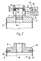
- Fig. 5 shows a coupling with recesses 93 in the bearing the grooves Coupling piece 8. These depressions can be rectangular or trapezoidal be formed and be formed as individual wells or as grooves. Grooves have proven to be particularly suitable. Burr-shaped engage in the grooves 93 Projections 144 of the clamping ring 25. Care is also taken here that the Walls of the projections and grooves are without additional deformation after the Do not touch the coupling.
- the clutch described above with reference to the figures can be part of the Pipe tubes are used.
- the coupling parts can also be used as separate Components are used in a variety of ways.
- a shaft tube 2 is shown with a coupling piece 8, which in the Shaft tube 2 fitted, glued to it with a high-strength adhesive and is additionally connected by means of rivets 81, screws or the like.
- the Coupling part 8 is provided with a thread 82, which is more common for receiving Pipe connection thread parts is formed.
- a Coupling part 82 is substantially disc-shaped and by shrinking and / or gluing and / or riveting or screwing to the rod 2 connected is.
- Linkage 2 of different diameters are also appropriate matched coupling parts 82 provided.
- the coupling part 82 is one for the linkage coaxial bore with internal thread 821 provided.
- a tubular coupling part 80 can be screwed in and by means of a stop 87 and / or lockable by bores 85 and bolts 86. Pass through the holes 85 both the threaded hole 821 and the coupling piece 80.
- the thread of the Tapped hole is relatively steep and coarse to avoid seizing during operation to avoid large power transmission.
- the tubular coupling piece 80 protrudes over part of its length end of the rod part 2 and is in this area with the Coupling part 3 from FIG. 1 can be coupled.
- the coupling piece 80 is with grooves 12 and possibly with a locking position R for receiving the coupling part 3 with its projections 11 Mistake.
- To deform the weakened by the grooves 12 or the like To avoid the edge area of the coupling piece is the outside of the Coupling piece 80 with a thread 801 at least in the area of the grooves 12 provided, onto which a ring 84 with a corresponding internal thread 841 can be screwed. This ring 84 thereby holds each turn of the thread 801 and causes one Stabilization of the marginal area.
- the diameter of the ring 84 is chosen so that it can be guided over the already installed coupling 3.
- the parts 80, 801, 82, 83 and the ring 84 in FIG. 7 are made of a plastic, in particular made of a cast polyamide PA 6 or PA 6.6.
- the bolts 11 and 86 are preferred made of metal.
- the connecting pins 81 can be screws or rivets. In front the connection of parts 2 and 82, the rod part 2 is heated and the end part 82 cooled. After shrink fitting, possibly in connection with a gluing of the adjacent surfaces and the mentioned rivets 81 can do this connection very well transfer high forces.
Landscapes
- Engineering & Computer Science (AREA)
- Mechanical Engineering (AREA)
- Mining & Mineral Resources (AREA)
- Geology (AREA)
- Life Sciences & Earth Sciences (AREA)
- General Life Sciences & Earth Sciences (AREA)
- Fluid Mechanics (AREA)
- Environmental & Geological Engineering (AREA)
- Physics & Mathematics (AREA)
- Geochemistry & Mineralogy (AREA)
- General Engineering & Computer Science (AREA)
- Earth Drilling (AREA)
- Mutual Connection Of Rods And Tubes (AREA)
- Drilling Tools (AREA)
- Processing Of Stones Or Stones Resemblance Materials (AREA)
- Soil Working Implements (AREA)
Description
- Fig. 1
- eine perspektivische Ansicht einer Diamantbohrkrone mit Schaftrohr und einer Kupplung zum Rohrgewindeanschluß,
- Fig. 2
- eine geschnittene Seitenansicht der miteinander verbundenen Teile gemäß Fig. 1,
- Fig. 3
- eine teilweise geschnittene Seitenansicht eines mit Nuten versehenen Kupplungsstückes,
- Fig. 4
- eine andere Seitenansicht der zu kuppelnden Teile,
- Fig. 5
- eine Kupplung mit Vertiefungen in dem mit Nuten versehenen Kupplungsstück,
- Fig. 6
- ein Schaftrohr mit Schraubabschluß,
- Fig. 7
- eine Weiterbildung der Kupplung.
Claims (10)
- Kupplung bestehend aus zwei zu kuppelnden Kupplungsteilen (3,8) eines Bohrgestänges mit Kraftübertragung von einer Bohrmaschine auf ein Schaftrohr (2) mit Bohrkrone, dadurch gekennzeichnet, daß das eine, Nuten aufweisende Kupplungsteil (8) und das eine, Vorsprünge (11) aufweisende Kupplungsstück (3) gegeneinander abgedichtet sind, daß das eine, Nuten aufweisende Kupplungsteil (8) und/oder das eine, Vorsprünge (11) aufweisende Kupplungsstück (3) und/oder das mit dem die Bohrkrone tragenden Rohr (2) an dem der Bohrkrone abgewandten Ende zu einer Einheit verbundene Kupplungsteil (8) und/oder ein die Kupplungsteile (3,8) kraftschlüssig verbindender Klemmring (25) aus einem leichten Nichteisenmaterial besteht.
- Kupplung nach Anspruch 1, dadurch gekennzeichnet, daß das Material Kunststoff ist.
- Kupplung nach Anspruch 1, dadurch gekennzeichnet, daß das Material ein glasfaserverstärkter Kunststoff ist.
- Kupplung nach Anspruch 1, dadurch gekennzeichnet, daß das Material ein Polyamid ist.
- Kupplung nach Anspruch 1, dadurch gekennzeichnet, daß das Material polykristallin ist.
- Kupplung nach Anspruch 1, dadurch gekennzeichnet, daß die Kupplungsteile (3,8) durch den Klemmring (25) miteinander kraftschlüssig verbindbar sind.
- Kupplung nach einem der Ansprüche 1 - 6, dadurch gekennzeichnet, daß Rohr (2) und Kupplungsteil (8) mittels eines Klebers verbunden sind.
- Kupplung nach einem der Ansprüche 1 - 7, dadurch gekennzeichnet, daß Rohr (2) und Kupplungsteil (8) durch Aufschrumpfen verbunden sind.
- Kupplung nach einem der Ansprüche 1 - 8, dadurch gekennzeichnet, daß Rohr (2) und Kupplungsteil (8) durch Nieten miteinander verbunden sind.
- Kupplung nach Anspruch 4, dadurch gekennzeichnet, daß das Material ein Gußpolyamid der Type PA6 oder PA 6,6 ist.
Applications Claiming Priority (5)
| Application Number | Priority Date | Filing Date | Title |
|---|---|---|---|
| DE3736302 | 1987-10-27 | ||
| DE19873736302 DE3736302A1 (de) | 1987-10-27 | 1987-10-27 | Kupplung, insbesondere fuer diamantbohrkrone mit schaftrohr und rohrgewindeanschluss |
| DE3813472A DE3813472A1 (de) | 1988-04-21 | 1988-04-21 | Kupplung, insbesondere fuer diamantbohrkrone mit schaftrohr und rohrgewindeanschluss |
| DE3813472 | 1988-04-21 | ||
| EP88117893A EP0314123B1 (de) | 1987-10-27 | 1988-10-27 | Kupplung, insbesondere für Diamantbohrkrone mit Schaftrohr und Rohrgewindeanschluss |
Related Parent Applications (2)
| Application Number | Title | Priority Date | Filing Date |
|---|---|---|---|
| EP88117893.3 Division | 1988-10-27 | ||
| EP88117893A Division EP0314123B1 (de) | 1987-10-27 | 1988-10-27 | Kupplung, insbesondere für Diamantbohrkrone mit Schaftrohr und Rohrgewindeanschluss |
Publications (2)
| Publication Number | Publication Date |
|---|---|
| EP0691484A1 EP0691484A1 (de) | 1996-01-10 |
| EP0691484B1 true EP0691484B1 (de) | 2001-01-10 |
Family
ID=25861152
Family Applications (2)
| Application Number | Title | Priority Date | Filing Date |
|---|---|---|---|
| EP95112857A Expired - Lifetime EP0691484B1 (de) | 1987-10-27 | 1988-10-27 | Kupplung für Bohrgestänge mit Kraftübertragung auf eine Bohrkrone |
| EP88117893A Expired - Lifetime EP0314123B1 (de) | 1987-10-27 | 1988-10-27 | Kupplung, insbesondere für Diamantbohrkrone mit Schaftrohr und Rohrgewindeanschluss |
Family Applications After (1)
| Application Number | Title | Priority Date | Filing Date |
|---|---|---|---|
| EP88117893A Expired - Lifetime EP0314123B1 (de) | 1987-10-27 | 1988-10-27 | Kupplung, insbesondere für Diamantbohrkrone mit Schaftrohr und Rohrgewindeanschluss |
Country Status (5)
| Country | Link |
|---|---|
| EP (2) | EP0691484B1 (de) |
| AT (2) | ATE136094T1 (de) |
| DE (2) | DE3855151D1 (de) |
| DK (1) | DK597088A (de) |
| ES (1) | ES2156175T3 (de) |
Families Citing this family (24)
| Publication number | Priority date | Publication date | Assignee | Title |
|---|---|---|---|---|
| US5687792A (en) * | 1995-09-27 | 1997-11-18 | Baker Hughes Incorporated | Drill pipe float valve and method of manufacture |
| US5746279A (en) * | 1996-02-20 | 1998-05-05 | Gas Research Institute | Method and apparatus for changing bits while drilling with a flexible shaft |
| SE511429C2 (sv) * | 1996-09-13 | 1999-09-27 | Seco Tools Ab | Verktyg, skärdel, verktygskropp för skärande bearbetning samt metod för montering av skärdel till verktygskropp |
| DE19650718A1 (de) * | 1996-12-06 | 1998-06-10 | Delco Imperial Establishment | Hohlbohrwerkzeug, insbesondere Diamantbohrwerkzeug |
| GB2324486B (en) * | 1997-04-24 | 2001-06-20 | Marcrist Ind Ltd | Masonry core-cutting tool |
| EP1083292A1 (de) * | 1999-09-10 | 2001-03-14 | Earth Tool Company L.L.C. | System mit auswechselbarem Bohrmeissel zum Richtungsbohren |
| FR2827203B1 (fr) * | 2001-07-12 | 2003-10-03 | Toolmatic Bvba | Tete d'aspiration, couronne et rallonge pour forage a sec |
| GB0213019D0 (en) | 2002-06-06 | 2002-07-17 | Clark John | Drilling attachment |
| FI115661B (fi) | 2002-12-23 | 2005-06-15 | Robit Rocktools Ltd | Teräsovitelma |
| DE102007019168A1 (de) | 2007-04-20 | 2008-10-23 | Geißler & Kuper GmbH Diamantwerkzeuge, Maschinen | Bohreinrichtung |
| WO2012150893A1 (en) * | 2011-05-04 | 2012-11-08 | Pct Systems Ab | Method and equipment to treat a fluid channel prior to a relining procedure and an exchangeable tool having a coupling mechanism to be used in connection thereto |
| DE102011089546A1 (de) * | 2011-12-22 | 2013-06-27 | Hilti Aktiengesellschaft | Bohrkrone mit einem austauschbaren Bohrkronenabschnitt |
| EP2745964A1 (de) * | 2012-12-21 | 2014-06-25 | HILTI Aktiengesellschaft | Schneidabschnitt |
| FR3014974B1 (fr) * | 2013-12-16 | 2016-01-01 | Leroy Somer Moteurs | Systeme d'accouplement d'une machine entrainante avec une machine entrainee |
| CN103697074A (zh) * | 2014-01-04 | 2014-04-02 | 陈焕祥 | 一种电机搅拌接头 |
| DE102015100922A1 (de) * | 2015-01-22 | 2016-07-28 | Newfrey Llc | Wechselmatrize, Fügewerkzeug und Fügeverfahren |
| EP3184215A1 (de) | 2015-12-22 | 2017-06-28 | HILTI Aktiengesellschaft | Set aus mehreren bohrschaftabschnitten zum aufbau einer bohrkrone |
| EP3184218A1 (de) | 2015-12-22 | 2017-06-28 | HILTI Aktiengesellschaft | Set aus mehreren bohrkronenabschnitten zum aufbau einer bohrkrone |
| EP3184219A1 (de) | 2015-12-22 | 2017-06-28 | HILTI Aktiengesellschaft | Bohrkrone |
| CN108798576B (zh) * | 2018-07-20 | 2023-11-10 | 广东鸿翔工程检测咨询有限公司 | 一种公路路面检测用钻孔取芯机 |
| IT201900011766A1 (it) * | 2019-07-15 | 2021-01-15 | Algra S P A | Dispositivo per la stabilizzazione controllata di codoli portautensili |
| CN110821945B (zh) * | 2019-11-07 | 2020-11-17 | 北京航空航天大学 | 一种中空传动轴内嵌液路旋转接头与中空传动轴连接件 |
| GB2594342A (en) * | 2020-04-23 | 2021-10-27 | Plumbingenuity Ltd | Tool |
| CN111894969A (zh) * | 2020-07-20 | 2020-11-06 | 邹城兖矿泰德工贸有限公司 | 强力型接杆 |
Citations (1)
| Publication number | Priority date | Publication date | Assignee | Title |
|---|---|---|---|---|
| US4072441A (en) * | 1976-04-15 | 1978-02-07 | Parker Manufacturing Company | Hole saw |
Family Cites Families (8)
| Publication number | Priority date | Publication date | Assignee | Title |
|---|---|---|---|---|
| US2240738A (en) * | 1937-07-14 | 1941-05-06 | Nat Supply Co | Rotary drilling rig |
| DE1097929B (de) * | 1960-01-25 | 1961-01-26 | Mannesmann Ag | Rohrverbindung fuer die Gestaengerohre eines Erdbohrers mit Vorortantrieb |
| BE660158A (de) * | 1965-02-24 | 1965-08-24 | ||
| US4305180A (en) * | 1979-12-14 | 1981-12-15 | International Telephone And Telegraph Corporation | Bayonet coupling nut |
| DE3412249A1 (de) * | 1984-04-02 | 1985-10-10 | Witte Bohrtechnik GmbH, 3060 Stadthagen | Vortriebsrohrsatz fuer den unterirdischen rohrvortrieb |
| DE3760820D1 (en) * | 1986-02-05 | 1989-11-23 | Geissler & Kuper Gmbh | Coupling, especially for a diamond drill bit with a tube shaft and tube winding connection |
| DE8603499U1 (de) | 1986-02-10 | 1990-08-02 | Thyssen Industrie AG Schmiedetechnik/Bergbautechnik, 4100 Duisburg | Balkengleisbremse für schienengebundene Fahrzeuge |
| DE8627861U1 (de) * | 1986-10-18 | 1986-12-18 | Geißler & Kuper GmbH Diamantwerkzeug - Wiederaufbereitung, 3100 Celle | Rohrgestänge, insbesondere für Diamantbohrkronen |
-
1988
- 1988-10-27 DE DE3855151T patent/DE3855151D1/de not_active Expired - Fee Related
- 1988-10-27 DK DK597088A patent/DK597088A/da not_active Application Discontinuation
- 1988-10-27 EP EP95112857A patent/EP0691484B1/de not_active Expired - Lifetime
- 1988-10-27 ES ES95112857T patent/ES2156175T3/es not_active Expired - Lifetime
- 1988-10-27 AT AT88117893T patent/ATE136094T1/de active
- 1988-10-27 AT AT95112857T patent/ATE198638T1/de not_active IP Right Cessation
- 1988-10-27 DE DE3856454T patent/DE3856454D1/de not_active Expired - Fee Related
- 1988-10-27 EP EP88117893A patent/EP0314123B1/de not_active Expired - Lifetime
Patent Citations (1)
| Publication number | Priority date | Publication date | Assignee | Title |
|---|---|---|---|---|
| US4072441A (en) * | 1976-04-15 | 1978-02-07 | Parker Manufacturing Company | Hole saw |
Also Published As
| Publication number | Publication date |
|---|---|
| EP0314123A2 (de) | 1989-05-03 |
| DK597088A (da) | 1989-04-28 |
| ATE198638T1 (de) | 2001-01-15 |
| ES2156175T3 (es) | 2001-06-16 |
| EP0314123A3 (en) | 1989-12-20 |
| EP0314123B1 (de) | 1996-03-27 |
| DE3856454D1 (de) | 2001-02-15 |
| DE3855151D1 (de) | 1996-05-02 |
| ATE136094T1 (de) | 1996-04-15 |
| DK597088D0 (da) | 1988-10-27 |
| EP0691484A1 (de) | 1996-01-10 |
Similar Documents
| Publication | Publication Date | Title |
|---|---|---|
| EP0691484B1 (de) | Kupplung für Bohrgestänge mit Kraftübertragung auf eine Bohrkrone | |
| DE2902299A1 (de) | Lochsaegeanordnung | |
| DE10130681A1 (de) | Selbstbohrende Blindnietmutter | |
| DE2817721A1 (de) | Kombiniertes bohr- und schraubwerkzeug | |
| DE3108438C2 (de) | Bohrwerkzeug | |
| DE3610749A1 (de) | Kraftantreibbarer schraubkopf | |
| EP0284745B1 (de) | Kupplung zwischen einem Werkzeugkopf und einem Werkzeugträger | |
| DE69103090T2 (de) | Schraubengewindekonstruktion. | |
| DE2056091C3 (de) | Spitzbohrwerkzeug | |
| EP0235581B1 (de) | Kupplung, insbesondere für Diamantbohrkrone mit Schaftrohr und Rohrgewindeanschluss | |
| DE8427440U1 (de) | Revolverkopf für eine Drehmaschine und hierzu passende Werkzeughalter | |
| DE3512929A1 (de) | Spannbacke | |
| DE3436733C2 (de) | ||
| DE19541163A1 (de) | Bohrwerkzeug, insbesondere zur Bearbeitung von Gestein | |
| DE69725185T2 (de) | Handbetätigtes futter | |
| DE3900140C1 (de) | ||
| DE3814365C2 (de) | Kupplung, insbesondere für Diamantbohrkrone mit Schaftrohr und Rohrgewindeanschluß | |
| DE2457505A1 (de) | Tiefloch-bohrkopf | |
| DE202022101626U1 (de) | Vorrichtung zur Begrenzung der Eingriffstiefe eines Zerspanungswerkzeugs | |
| DE1627011C3 (de) | Halter für axial einstellbare Werkzeuge | |
| DE102019111843B4 (de) | Zerspanungswerkzeug | |
| DE2801828A1 (de) | Loesbarer klemmhalter mit einem handgriff zum aufsetzen vorzugsweise auf den spindelhals einer bohrmaschine | |
| DE3813472A1 (de) | Kupplung, insbesondere fuer diamantbohrkrone mit schaftrohr und rohrgewindeanschluss | |
| EP3693532B1 (de) | Vorrichtung zum bohren in erdreich, verfahren zum herstellen einer vorrichtung zum bohren in erdreich, verfahren zum warten einer vorrichtung zum bohren in erdreich und verwendung einer vorrichtung zum bohren in erdreich | |
| DE2617554C3 (de) | Verbindung für Blechrohre, insbesondere für den Brunnenbau und für Pfahlgründungen |
Legal Events
| Date | Code | Title | Description |
|---|---|---|---|
| PUAI | Public reference made under article 153(3) epc to a published international application that has entered the european phase |
Free format text: ORIGINAL CODE: 0009012 |
|
| AC | Divisional application: reference to earlier application |
Ref document number: 314123 Country of ref document: EP |
|
| AK | Designated contracting states |
Kind code of ref document: A1 Designated state(s): AT BE CH DE ES FR GB GR IT LI LU NL SE |
|
| 17P | Request for examination filed |
Effective date: 19951122 |
|
| 17Q | First examination report despatched |
Effective date: 19970425 |
|
| RTI1 | Title (correction) |
Free format text: FORCE TRANSMITTING COUPLING FOR A TUBE SHAFT TO AN ANNULAR DRILL BIT |
|
| GRAG | Despatch of communication of intention to grant |
Free format text: ORIGINAL CODE: EPIDOS AGRA |
|
| GRAG | Despatch of communication of intention to grant |
Free format text: ORIGINAL CODE: EPIDOS AGRA |
|
| GRAH | Despatch of communication of intention to grant a patent |
Free format text: ORIGINAL CODE: EPIDOS IGRA |
|
| GRAH | Despatch of communication of intention to grant a patent |
Free format text: ORIGINAL CODE: EPIDOS IGRA |
|
| GRAA | (expected) grant |
Free format text: ORIGINAL CODE: 0009210 |
|
| AC | Divisional application: reference to earlier application |
Ref document number: 314123 Country of ref document: EP |
|
| AK | Designated contracting states |
Kind code of ref document: B1 Designated state(s): AT BE CH DE ES FR GB GR IT LI LU NL SE |
|
| PG25 | Lapsed in a contracting state [announced via postgrant information from national office to epo] |
Ref country code: SE Free format text: LAPSE BECAUSE OF FAILURE TO SUBMIT A TRANSLATION OF THE DESCRIPTION OR TO PAY THE FEE WITHIN THE PRESCRIBED TIME-LIMIT Effective date: 20010110 Ref country code: GR Free format text: LAPSE BECAUSE OF NON-PAYMENT OF DUE FEES Effective date: 20010110 |
|
| REF | Corresponds to: |
Ref document number: 198638 Country of ref document: AT Date of ref document: 20010115 Kind code of ref document: T |
|
| REG | Reference to a national code |
Ref country code: CH Ref legal event code: EP |
|
| REF | Corresponds to: |
Ref document number: 3856454 Country of ref document: DE Date of ref document: 20010215 |
|
| GBT | Gb: translation of ep patent filed (gb section 77(6)(a)/1977) |
Effective date: 20010220 |
|
| ITF | It: translation for a ep patent filed | ||
| ET | Fr: translation filed | ||
| REG | Reference to a national code |
Ref country code: ES Ref legal event code: FG2A Ref document number: 2156175 Country of ref document: ES Kind code of ref document: T3 |
|
| REG | Reference to a national code |
Ref country code: CH Ref legal event code: NV Representative=s name: KELLER & PARTNER PATENTANWAELTE AG |
|
| PG25 | Lapsed in a contracting state [announced via postgrant information from national office to epo] |
Ref country code: LU Free format text: LAPSE BECAUSE OF NON-PAYMENT OF DUE FEES Effective date: 20011027 |
|
| PLBE | No opposition filed within time limit |
Free format text: ORIGINAL CODE: 0009261 |
|
| STAA | Information on the status of an ep patent application or granted ep patent |
Free format text: STATUS: NO OPPOSITION FILED WITHIN TIME LIMIT |
|
| REG | Reference to a national code |
Ref country code: GB Ref legal event code: IF02 |
|
| 26N | No opposition filed | ||
| PGFP | Annual fee paid to national office [announced via postgrant information from national office to epo] |
Ref country code: GB Payment date: 20021029 Year of fee payment: 15 |
|
| PGFP | Annual fee paid to national office [announced via postgrant information from national office to epo] |
Ref country code: FR Payment date: 20021030 Year of fee payment: 15 |
|
| PGFP | Annual fee paid to national office [announced via postgrant information from national office to epo] |
Ref country code: NL Payment date: 20021031 Year of fee payment: 15 Ref country code: AT Payment date: 20021031 Year of fee payment: 15 |
|
| PGFP | Annual fee paid to national office [announced via postgrant information from national office to epo] |
Ref country code: BE Payment date: 20021104 Year of fee payment: 15 |
|
| PGFP | Annual fee paid to national office [announced via postgrant information from national office to epo] |
Ref country code: ES Payment date: 20021106 Year of fee payment: 15 |
|
| PGFP | Annual fee paid to national office [announced via postgrant information from national office to epo] |
Ref country code: CH Payment date: 20021120 Year of fee payment: 15 |
|
| PGFP | Annual fee paid to national office [announced via postgrant information from national office to epo] |
Ref country code: DE Payment date: 20021212 Year of fee payment: 15 |
|
| PG25 | Lapsed in a contracting state [announced via postgrant information from national office to epo] |
Ref country code: GB Free format text: LAPSE BECAUSE OF NON-PAYMENT OF DUE FEES Effective date: 20031027 Ref country code: AT Free format text: LAPSE BECAUSE OF NON-PAYMENT OF DUE FEES Effective date: 20031027 |
|
| PG25 | Lapsed in a contracting state [announced via postgrant information from national office to epo] |
Ref country code: LI Free format text: LAPSE BECAUSE OF NON-PAYMENT OF DUE FEES Effective date: 20031031 Ref country code: CH Free format text: LAPSE BECAUSE OF NON-PAYMENT OF DUE FEES Effective date: 20031031 Ref country code: BE Free format text: LAPSE BECAUSE OF NON-PAYMENT OF DUE FEES Effective date: 20031031 |
|
| BERE | Be: lapsed |
Owner name: *GEISSLER & KUPER G.M.B.H. DIAMANTWERKZEUGE MASCHI Effective date: 20031031 |
|
| PG25 | Lapsed in a contracting state [announced via postgrant information from national office to epo] |
Ref country code: NL Free format text: LAPSE BECAUSE OF NON-PAYMENT OF DUE FEES Effective date: 20040501 Ref country code: DE Free format text: LAPSE BECAUSE OF NON-PAYMENT OF DUE FEES Effective date: 20040501 |
|
| REG | Reference to a national code |
Ref country code: CH Ref legal event code: PL |
|
| GBPC | Gb: european patent ceased through non-payment of renewal fee |
Effective date: 20031027 |
|
| PG25 | Lapsed in a contracting state [announced via postgrant information from national office to epo] |
Ref country code: FR Free format text: LAPSE BECAUSE OF NON-PAYMENT OF DUE FEES Effective date: 20040630 |
|
| NLV4 | Nl: lapsed or anulled due to non-payment of the annual fee |
Effective date: 20040501 |
|
| REG | Reference to a national code |
Ref country code: FR Ref legal event code: ST |
|
| PG25 | Lapsed in a contracting state [announced via postgrant information from national office to epo] |
Ref country code: IT Free format text: LAPSE BECAUSE OF NON-PAYMENT OF DUE FEES;WARNING: LAPSES OF ITALIAN PATENTS WITH EFFECTIVE DATE BEFORE 2007 MAY HAVE OCCURRED AT ANY TIME BEFORE 2007. THE CORRECT EFFECTIVE DATE MAY BE DIFFERENT FROM THE ONE RECORDED. Effective date: 20051027 |
|
| PG25 | Lapsed in a contracting state [announced via postgrant information from national office to epo] |
Ref country code: ES Free format text: LAPSE BECAUSE OF NON-PAYMENT OF DUE FEES Effective date: 20031031 |
|
| REG | Reference to a national code |
Ref country code: ES Ref legal event code: FD2A Effective date: 20180629 |
|
| PG25 | Lapsed in a contracting state [announced via postgrant information from national office to epo] |
Ref country code: ES Free format text: LAPSE BECAUSE OF NON-PAYMENT OF DUE FEES Effective date: 20031028 |