EP0687882B1 - Mécanisme de mise à poste d'une munition - Google Patents
Mécanisme de mise à poste d'une munition Download PDFInfo
- Publication number
- EP0687882B1 EP0687882B1 EP95401376A EP95401376A EP0687882B1 EP 0687882 B1 EP0687882 B1 EP 0687882B1 EP 95401376 A EP95401376 A EP 95401376A EP 95401376 A EP95401376 A EP 95401376A EP 0687882 B1 EP0687882 B1 EP 0687882B1
- Authority
- EP
- European Patent Office
- Prior art keywords
- rotation
- abutment
- ammunition
- mechanism according
- lever
- Prior art date
- Legal status (The legal status is an assumption and is not a legal conclusion. Google has not performed a legal analysis and makes no representation as to the accuracy of the status listed.)
- Expired - Lifetime
Links
Images


Classifications
-
- F—MECHANICAL ENGINEERING; LIGHTING; HEATING; WEAPONS; BLASTING
- F41—WEAPONS
- F41A—FUNCTIONAL FEATURES OR DETAILS COMMON TO BOTH SMALLARMS AND ORDNANCE, e.g. CANNONS; MOUNTINGS FOR SMALLARMS OR ORDNANCE
- F41A9/00—Feeding or loading of ammunition; Magazines; Guiding means for the extracting of cartridges
- F41A9/01—Feeding of unbelted ammunition
- F41A9/06—Feeding of unbelted ammunition using cyclically moving conveyors, i.e. conveyors having ammunition pusher or carrier elements which are emptied or disengaged from the ammunition during the return stroke
- F41A9/09—Movable ammunition carriers or loading trays, e.g. for feeding from magazines
- F41A9/10—Movable ammunition carriers or loading trays, e.g. for feeding from magazines pivoting or swinging
- F41A9/13—Movable ammunition carriers or loading trays, e.g. for feeding from magazines pivoting or swinging in a vertical plane
- F41A9/14—Movable ammunition carriers or loading trays, e.g. for feeding from magazines pivoting or swinging in a vertical plane which is transverse to the barrel axis
-
- F—MECHANICAL ENGINEERING; LIGHTING; HEATING; WEAPONS; BLASTING
- F41—WEAPONS
- F41A—FUNCTIONAL FEATURES OR DETAILS COMMON TO BOTH SMALLARMS AND ORDNANCE, e.g. CANNONS; MOUNTINGS FOR SMALLARMS OR ORDNANCE
- F41A9/00—Feeding or loading of ammunition; Magazines; Guiding means for the extracting of cartridges
- F41A9/38—Loading arrangements, i.e. for bringing the ammunition into the firing position
- F41A9/39—Ramming arrangements
- F41A9/42—Rammers separate from breech-block
Definitions
- the subject of the present invention is a mechanism for placing of ammunition in the breech chamber of a medium or large caliber weapon, comprising on the one hand ammunition supply device which is driven in rotation by a drive device and on the other hand less a means of delivery and a means of wedging the ammunition operating successively, the delivery means and the wedging means being integral in rotation with the feeding device, the latter performing during a round of ammunition stationing successively a first rotation positioning the ammunition on the one hand the axis of the cylinder head chamber and secondly the means of repression to allow him to repress the ammunition, and a second rotation positioning the means to allow it to carry out the the ammunition in the forcing cone.
- the first and second rotations take place around two different axes, i.e. with a complex movement, hence a mechanical complexity which has as a corollary a relative mechanical fragility of the whole, hardly compatible with the requirements of new types of artillery equipment.
- French patent application 2,346,667 describes a loading device in which a tilting bucket receives a propellant charge and pushes in a single operation the charge and a projectile in the chamber of the weapon. In this device the projectile is trapped by inertia during the stop of the trough. Such a wedging mode is not sufficiently reliable.
- the subject of the present invention is a mechanism for stationing of the aforementioned type, but which has a mechanism both simpler and more robust than in Art Prior.
- the basic idea of the invention is to perform both rotations around a single axis so as to obtain the desired simplicity, and as a result, to also win over the time of a full charging cycle.
- the shift mechanism according to the invention is characterized in that it comprises a rotating part allowing the first and second rotations of the feeding device are carried out around the same axis of rotation cooperating with a retractable stop means allowing to stop the rotation of the feeding device in a position corresponding to the end of the first rotation.
- the retractable stop means may include a retracting device moving the stop means between two positions, namely a first position, active, in which the stop means is capable of causing the stopping of the rotation of the feeding device at the end first rotation, and a second position, inactive, in which the stop means is deleted and does not act on the rotation of the feeding device.
- the retractable stop means advantageously comprises a first stop lever sliding longitudinally relative to said rotary part, but integral in rotation with said part, the feed device comprising means for sliding the first stop lever along said rotating part between said first and second positions.
- the first stop lever can particular include a peripheral groove, the means for moving the first lever then comprising a fork engaging in said groove.
- the stop means retractable has a second stop lever cooperating with a end stop of first rotation, the first stop lever being likely to cause the second stop lever only when is in its first position.
- the fork can be articulated around an axis of articulation.
- the range can include a first and a second branches each of which has a region such as an engaging finger in said groove.
- the first branch may include, at one end, a control finger constituting said means for making slide the first stop lever.
- the post-setting mechanism may include a rigid box supporting the drive device, the retractable stop means and said rotary part.
- the mechanism may include means for controlling, between steps a and c , an outward movement of the delivery means so as to effect said delivery of the ammunition and for controlling, between steps c and d , an outward movement of the jamming means so as to effect said jamming of the ammunition, then a return movement of the jamming means.
- the mechanism comprises means for controlling, during step d , a return movement of the delivery means.
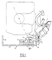
- a feeding device a munition 50 comprises a stretcher 1 of semi-circular shape, the concavity is directed upwards and which is provided with a anti-extraction device 4, known per se, which is intended to prevent the ejection of the shell 50 during the rotation of the stretcher 1.
- the stretcher 1 is movable in rotation about a single axis, which is the axis of rotation of a cylindrical part 11.
- a support comprising on the one hand a perforated plate 22 at 26 which extends radially from the cylindrical part 11 to the stretcher 1 and on the other hand two lateral support elements 24 and 25 orthogonal to plate 22 and whose ends 24 'and 25' come enclose stretcher 1 so as to constitute a mechanical assembly rigid.
- the stretcher 1 is rotated by a rotary actuator 6 to helical piston.
- a chain backer 2 driven by a hydraulic motor and a cylinder linear clamp 3 are mounted on stretcher 1 and are integral with its rotation around the axis of the part 11.
- the whole is powered by an electro-hydraulic block, itself controlled by an electric control console.
- a lever 7 carrying a drive finger 18 is integral in rotation of the part 11, but its position along it is controlled by a fork 8 actuated by a stop cylinder 5.
- This driving in rotation of the lever 7, regardless of its position longitudinal along the part 11, is obtained by grooves complementary 15 of an extension 11 'of the part 11, and of the lever 7, which are shown in FIGS. 8 and 9.
- the finger 18 of the lever 7 allows to rotate in rotation until a damping stop 10 a second lever 9 carrying at its end 14 a stop finger 12.
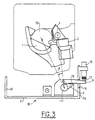
- lever 9 is recalled by its own weight or by a spring (not shown) in a low position where it is released from the stop 10 and comes to rest in its bottom dead center on a lower edge 16 of an opening of one of the edges 34 of a box rigid U-shaped support 30 having a bottom plate 31 and a second flange 33.
- the box 30 stiffens the assembly and carries a U-shaped plate 36, whose branches 37 and 38 support the rotary actuator 6, the retractable stop mechanism 5, 7, 8, 9 and a end of the part 11, the other end of which is held by a wing 39 forming an extension of the bottom plate 31, which adjoins the ledge 34.
- the shift mechanism then operates according to the following cycle:
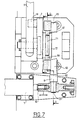
- a shell 50 is deposited in stretcher 1, which is in the insertion position shown in Figures 1 and 2. In this position, the chain repressor 2 is at rest. The linear cylinder of jam 3 is retracted rod, the stop cylinder 5 is retracted rod (see FIG. 7), which corresponds to the active position of the lever 7, and the rotary actuator 6 is at rest. The anti-extraction device 4 prevents the shell from being ejected during the first rotational movement of the stretcher 1.
- a first rotation of angle ⁇ of the stretcher 1 is carried out around the axis of the part 11 from the position shown in the Figure 1 to the position shown in Figure 3, in which the arm 9, driven by the finger 18, is applied by its finger stop 12 against the damper stop 10.
- the shell 50 sees its axis aligned with that of the breech chamber 40 of the barrel and the chain repeller 2 is in a position in which it can push back shell 50 from stretcher 1 to the cylinder head chamber 40.
- This discharge stage is initiated by a position detector of stretcher 1 which controls the advance of the chain repressor 2.
- a second position detector controls the output of the stopper cylinder rod 5, which has the effect to release finger 18 from its action on lever 9, which falls to its bottom dead center, and release the grooved lever 7 to allow it to continue its rotation without exerting any action on the lever 9.
- the stretcher 1 then performs a second rotation of angle ⁇ , always under the action of the rotary actuator 6 left under pressure from the position shown in Figure 3 to the position shown in Figure 5.
- the cylinder wedge 3 is brought into alignment with the cylinder head chamber 40 of the mouth to fire.
- a position detector on stretcher 1 controls the exit of the rod 23 of the jamming cylinder 3 and locks in position firing the shell 50 in the forcing cone 60 of the chamber 40.
- An electro-hydraulic device hydraulically connected to the rod 23 of the jack 3 controls, as soon as the oil flow drops, the re-entry of the rod 23.
- a re-entry detector of the rod 23 controls then return the stretcher 1 to the starting position (figure 1) as well that the return of the repressor 2.
- a last detector in the start position controls the retraction of the stop cylinder 5, which again positions the lever 7 in active position. The loading device is then ready for a new cycle.
- the device which has been described above, allows a gain of time on the one hand due to the fact that the return of the repressor 2 can be done entirely in masked time and, on the other hand, that the time of return of rotation of the arm is faster than in the prior art thanks to the unique movement, which contributes to the reduction of time of a complete cycle and consequently improves the rate of fire of the equipment.
- Figure 7 shows the lever 7 in its active position where the pin 18 rotates the lever 9. This position corresponds to the rod 82 position retracted from the stop cylinder 5.
- the fork 8 has the general shape of an inverted U (see Figure 9) which has an upper central branch 84 and two lateral branches 83 and 85 which extend downward. At its upper part 88, which overcomes the central branch 84, a hinge 89 is arranged allowing the fork 8 to be movable in rotation about an axis horizontal perpendicular to the axis of rotation of the part 11.
- the lower part of branch 83 has an extension 82 which ends with a finger 81 which engages in the rod 82, which allows control the movement of the fork 8.
- the part median of branches 83 and 85 has extensions 83 and 87 engaging in a groove 71 of a cylindrical piece 72 extending the lever 7 along the axis of the part 11.
- the fork 8 is thus movable between the active position of the lever 7 (in solid lines in FIG. 10) in which the finger 18 can rotate lever 9 and a second position making a angle with the vertical and in which, the jack 5 is in position rod 82 extended, finger 18 is moved (to the right in the figure 10) so as to be moved away from lever 9 (see the dotted lines at the figure 10).
- Figure 8 also shows the various positions of the levers 7 and 9 and more particularly the three characteristic positions of the lever 7, namely the first starting position shown in line full, then, after the first rotation, the first position corresponding to the abutment of the lever 9 (also shown in dotted) then finally, the rotation pushing in the direction counterclockwise, the third position after a second rotation in which a rear extension 19 of the lever 7 abuts on a stop 13 indicating the end of the second rotation.
Landscapes
- Engineering & Computer Science (AREA)
- General Engineering & Computer Science (AREA)
- Portable Nailing Machines And Staplers (AREA)
Description
- les figures 1 et 2 représentent, respectivement en vue avant et en vue latérale droite (coupe partielle AA de la figure 1), un dispositif selon l'invention, en position d'introduction d'une munition ;
- la figure 3 représente le dispositif de la figure 1 après une première rotation du dispositif d'amenage ;
- la figure 4 représente, en vue de dessus, l'introduction d'une munition dans la chambre de culasse d'un canon ;
- la figure 5 représente le dispositif de la figure 3, après deuxième rotation du dispositif d'amenage pour mise en position du vérin de coincement ;
- la figure 6 représente, en vue de dessus, la fin de l'introduction et le coincement de la munition dans le cône de forcement d'un tube de bouche à feu ;
- la figure 7 représente, en vue de dessus avec coupe partielle BB de la figure 5, un mode de réalisation préféré du dispositif d'escamotage de la butée ;
- la figure 8 est une coupe transversale CC de la figure 7, illustrant deux positions caractéristiques du moyen de butée escamotable selon l'invention ;
- la figure 9 est une coupe transversale DD de la figure 7 ;
- la figure 10 est une vue latérale de la figure 9 illustrant deux positions caractéristiques du déplacement de la fourchette selon un mode de réalisation préféré de l'invention ;
- la figure 11 est une vue en perspective d'un dispositif selon l'invention, avec enlèvement du dispositif d'escamotage de la butée escamotable.
Claims (12)
- Mécanisme de mise à poste d'une munition (30) dans la chambre (40) de culasse d'une arme de moyen ou de gros calibre, comportant, d'une part, un dispositif d'amenage (1) de la munition qui est entraíné en rotation par un dispositif d'entraínement (6) et, d'autre part, au moins un moyen de refoulement (2) et un moyen de coincement (3) de la munition opérant successivement, le moyen de refoulement (2) et le moyen de coincement (3) étant solidaires en rotation du dispositif d'amenage (1), ce dernier effectuant au cours d'un cycle de mise à poste de la munition successivement une première rotation (α) positionnant, d'une part, la munition dans l'axe de la chambre (40) de culasse et, d'autre part, le moyen de refoulement pour lui permettre d'effectuer un refoulement de la munition et une deuxième rotation (β) positionnant le moyen de coincement pour lui permettre d'effectuer le coincement de la munition dans le cône de forcement (60), caractérisé en ce qu'il comporte une pièce rotative (11) permettant que la première (α) et la deuxième (β) rotation du dispositif d'amenage (1) s'effectuent autour d'un même axe de rotation coopérant avec un moyen de butée (7, 9) escamotable permettant d'arrêter la rotation du dispositif d'amenage (1) dans une position correspondant à la fin de la première rotation (α).
- Mécanisme selon la revendication 1, caractérisé en ce que le moyen de butée (7, 9) escamotable comporte un dispositif d'escamotage (5, 82) déplaçant le moyen de butée (7, 9) entre deux positions, à savoir une première position, active, dans laquelle le moyen de butée (7, 9) est assure l'arrêt de la rotation du dispositif d'amenage (1) en fin de première rotation (α), et une deuxième position, inactive, dans laquelle le moyen de butée (7, 9) est effacé et n'agit pas sur la rotation du dispositif d'amenage (1).
- Mécanisme selon la revendication 2, caractérisé en ce que le moyen de butée escamotable comporte un premier levier de butée (7) coulissant longitudinalement par rapport à ladite pièce rotative (11), notamment grâce à des cannelures (15), mais solidaire en rotation de ladite pièce (11) et en ce que le dispositif d'escamotage comporte un moyen (8) pour faire coulisser le premier levier de butée le long de ladite pièce rotative (11) entre lesdites première et deuxième positions.
- Mécanisme selon la revendication 3, caractérisé en ce que le premier levier de butée (7) comporte une rainure périphérique (71) et en ce que le moyen pour déplacer le premier levier (7) comporte une fourchette (8) s'engageant dans ladite rainure (71).
- Mécanisme selon une des revendications 3 ou 4, caractérisé en ce que le moyen de butée escamotable comporte un deuxième levier de butée (9) coopérant avec une butée (10) de fin de première rotation et en ce que le premier levier de butée (7) est susceptible d'entraíner le deuxième levier de butée (9) seulement lorsqu'il (7) se trouve dans ladite première position.
- Mécanisme selon une des revendications 4 ou 5, caractérisé en ce que la fourchette (8) est articulée autour d'un axe d'articulation (89).
- Mécanisme selon une des revendications 4 à 6, caractérisé en ce que la fourchette (8) comporte une première (83) et une deuxième branche (85) dont chacune présente un doigt (86, 87) s'engageant dans ladite rainure (71).
- Mécanisme selon la revendication 7, caractérisé en ce que la première branche (83) comporte, à une extrémité un doigt de commande (81) constituant ledit moyen pour faire coulisser le premier levier de butée (7).
- Mécanisme selon une des revendications précédentes, caractérisé en ce qu'il comporte un caisson rigide supportant le dispositif d'entraínement (6), le moyen de butée escamotable (7, 9) et ladite pièce rotative (11).
- Mécanisme selon une des revendications 2 à 9, caractérisé en ce qu'il comporte un dispositif de commande assurant le séquencement suivant de la rotation du dispositif d'amenage (1) :a) déplacer le dispositif d'entraínement (6) pour effectuer la première rotation, le moyen de butée escamotable (7, 9) étant dans sa première position ;b) placer le moyen de butée escamotable (7, 9) dans sa deuxième position ;c) déplacer le dispositif d'entraínement (6) pour effectuer la deuxième rotation ;d) déplacer le dispositif d'entraínement (6) pour effectuer le retour des deuxième et première rotations ;e) placer le moyen de butée escamotable (7, 9) dans sa première position.
- Mécanisme selon la revendication 10, caractérisé en ce qu'il comporte un moyen pour commander, entre les étapes a et c, un déplacement aller du moyen de refoulement (2) de manière à effectuer ledit refoulement de la munition (50) et pour commander, entre les étapes c et d, un déplacement aller du moyen de coincement (3) de manière à effectuer ledit coincement de la munition (50), puis un déplacement retour du moyen de coincement (3).
- Mécanisme selon une des revendications 10 ou 11, caractérisé en ce qu'il comporte un moyen pour commander, au cours de l'étape d, un déplacement retour du moyen de refoulement (2).
Applications Claiming Priority (2)
| Application Number | Priority Date | Filing Date | Title |
|---|---|---|---|
| FR9407355 | 1994-06-16 | ||
| FR9407355A FR2721387B1 (fr) | 1994-06-16 | 1994-06-16 | Mécanisme de mise à poste d'une munition. |
Publications (2)
| Publication Number | Publication Date |
|---|---|
| EP0687882A1 EP0687882A1 (fr) | 1995-12-20 |
| EP0687882B1 true EP0687882B1 (fr) | 1999-05-19 |
Family
ID=9464272
Family Applications (1)
| Application Number | Title | Priority Date | Filing Date |
|---|---|---|---|
| EP95401376A Expired - Lifetime EP0687882B1 (fr) | 1994-06-16 | 1995-06-13 | Mécanisme de mise à poste d'une munition |
Country Status (4)
| Country | Link |
|---|---|
| US (1) | US5563363A (fr) |
| EP (1) | EP0687882B1 (fr) |
| DE (1) | DE69509703T2 (fr) |
| FR (1) | FR2721387B1 (fr) |
Families Citing this family (7)
| Publication number | Priority date | Publication date | Assignee | Title |
|---|---|---|---|---|
| US5773747A (en) * | 1996-05-07 | 1998-06-30 | United Defense, Lp | Two-piece ammunition flick ram |
| US6073534A (en) * | 1998-01-14 | 2000-06-13 | General Dynamics Armament Systems, Inc. | Transfer mechanism and method for uploading and downloading propellant charges and projectiles |
| FR2796713B1 (fr) | 1999-07-22 | 2002-09-13 | Giat Ind Sa | Dispositif d'aide au chargement pour artillerie |
| US6513415B2 (en) * | 2001-03-22 | 2003-02-04 | United Defense Lp | Propellant retention device |
| AU2008302516B2 (en) | 2007-09-17 | 2013-09-19 | Tecpharma Licensing Ag | Insertion devices for infusion devices |
| IT1400863B1 (it) * | 2010-06-22 | 2013-07-02 | Oto Melara Spa | Sistema di evacuazione bossoli |
| DE102017107442B4 (de) * | 2017-04-06 | 2021-03-18 | Krauss-Maffei Wegmann Gmbh & Co. Kg | Vorrichtung zum Laden einer Rohrwaffe mit Munitionskörpern |
Family Cites Families (8)
| Publication number | Priority date | Publication date | Assignee | Title |
|---|---|---|---|---|
| US1682323A (en) * | 1924-06-26 | 1928-08-28 | Thomas A Conlon | Mechanical loader for cannon |
| GB578742A (en) * | 1941-08-20 | 1946-07-10 | Desmond Walter Molins | Improvements in or relating to breech loading mechanism for ordnance |
| SE413264B (sv) * | 1976-03-31 | 1980-05-12 | Bofors Ab | Laddningsanordning vid ett eldvapen |
| US4183281A (en) * | 1976-03-31 | 1980-01-15 | Aktiebolaget Bofors | Method of and device for loading a firearm |
| FR2448121A1 (fr) * | 1979-02-05 | 1980-08-29 | France Etat | Dispositif de mise a poste de l'obus pour materiel d'artillerie |
| US4457209A (en) * | 1980-08-27 | 1984-07-03 | Fmc Corporation | Automated large caliber ammunition handling system |
| EP0051119B1 (fr) * | 1980-08-27 | 1985-02-06 | Fmc Corporation | Système de chargement automatique en munitions à gros calibre |
| DE3306935A1 (de) * | 1983-02-28 | 1984-08-30 | Rheinmetall GmbH, 4000 Düsseldorf | Ladeschalenanordnung an einer rohrwaffe |
-
1994
- 1994-06-16 FR FR9407355A patent/FR2721387B1/fr not_active Expired - Fee Related
-
1995
- 1995-06-06 US US08/471,727 patent/US5563363A/en not_active Expired - Lifetime
- 1995-06-13 EP EP95401376A patent/EP0687882B1/fr not_active Expired - Lifetime
- 1995-06-13 DE DE69509703T patent/DE69509703T2/de not_active Expired - Lifetime
Also Published As
| Publication number | Publication date |
|---|---|
| EP0687882A1 (fr) | 1995-12-20 |
| FR2721387B1 (fr) | 1996-08-14 |
| US5563363A (en) | 1996-10-08 |
| DE69509703T2 (de) | 1999-10-14 |
| DE69509703D1 (de) | 1999-06-24 |
| FR2721387A1 (fr) | 1995-12-22 |
Similar Documents
| Publication | Publication Date | Title |
|---|---|---|
| EP0687882B1 (fr) | Mécanisme de mise à poste d'une munition | |
| EP0783094B1 (fr) | Dispositif de transfert des charges propulsives entre un magasin et un système de chargement dans la chambre d'un canon | |
| EP1070932B1 (fr) | Dispositif d'aide au chargement d'une arme dotée d'une culasse à vis | |
| EP0362064A1 (fr) | Arme automatique à barillet, à grande cadence de tir | |
| FR2463379A1 (fr) | Arme de tir a air precomprime | |
| EP0571285B1 (fr) | Arme automatique à chambre basculante pour le tir de munitions cylindriques télescopées | |
| EP0571265A1 (fr) | Système de chargement d'une munition dans une chambre pivotante | |
| EP0140782B1 (fr) | Dispositif d'alimentation et de chargement tout azimut et tout site d'une arme en munitions | |
| EP2627963A1 (fr) | Pistolet semi-automatique a canon coulissant | |
| LU82629A1 (fr) | Mecanisme de surete pour mitrailleuse rotative a tir tres rapide | |
| EP0684442B1 (fr) | Dispositif d'alimentation en munitions pour armes automatiques | |
| EP0571266B1 (fr) | Système de chargement d'une munition dans une chambre pivotante d'une arme | |
| FR2547042A1 (fr) | Double alimentation en munitions pour armes automatiques | |
| FR2718837A1 (fr) | Arme à feu automatique multitubes de petit ou moyen calibre du type GATLING, notamment destinée au tir de munitions télescopées. | |
| EP0153242B1 (fr) | Dispositif pour le chargement automatique de munitions dans un canon | |
| EP0531595A1 (fr) | Dispositif de sécurité pour arme automatique | |
| EP0599683A1 (fr) | Méthode de chargement d'une munition dans une chambre pivotante d'une arme, et système de mise en oeuvre | |
| EP0362066B1 (fr) | Arme automatique de moyen calibre, à grande cadence de tir | |
| EP0664430B1 (fr) | Dispositif de chargement de munitions dans une arme montée en tourelle | |
| EP0660067B1 (fr) | Dispositif de déchargement d'une munition engagée dans une arme montée en tourelle | |
| FR2726637A1 (fr) | Dispositif pour refouler une munition dans le tube d'un canon, et pour effectuer l'operation inverse | |
| FR2704943A1 (fr) | Dispositif de chargement semi-automatique de canons, notamment de canons équipant des tourelles de chars. | |
| FR2600408A1 (fr) | Systeme automatique d'alimentation en munition et de chargement d'armes a air comprime | |
| FR1426298A (fr) | Perfectionnements aux pistolets de scellement à répétition | |
| CH591670A5 (en) | Automatic firearm with sliding breech - has mechanism lifting cartridges to breech and upper and lower cartridge stops |
Legal Events
| Date | Code | Title | Description |
|---|---|---|---|
| PUAI | Public reference made under article 153(3) epc to a published international application that has entered the european phase |
Free format text: ORIGINAL CODE: 0009012 |
|
| AK | Designated contracting states |
Kind code of ref document: A1 Designated state(s): DE GB IT NL SE |
|
| 17P | Request for examination filed |
Effective date: 19960201 |
|
| 17Q | First examination report despatched |
Effective date: 19970926 |
|
| GRAG | Despatch of communication of intention to grant |
Free format text: ORIGINAL CODE: EPIDOS AGRA |
|
| GRAG | Despatch of communication of intention to grant |
Free format text: ORIGINAL CODE: EPIDOS AGRA |
|
| GRAH | Despatch of communication of intention to grant a patent |
Free format text: ORIGINAL CODE: EPIDOS IGRA |
|
| GRAH | Despatch of communication of intention to grant a patent |
Free format text: ORIGINAL CODE: EPIDOS IGRA |
|
| GRAA | (expected) grant |
Free format text: ORIGINAL CODE: 0009210 |
|
| AK | Designated contracting states |
Kind code of ref document: B1 Designated state(s): DE GB IT NL SE |
|
| PG25 | Lapsed in a contracting state [announced via postgrant information from national office to epo] |
Ref country code: NL Free format text: LAPSE BECAUSE OF FAILURE TO SUBMIT A TRANSLATION OF THE DESCRIPTION OR TO PAY THE FEE WITHIN THE PRESCRIBED TIME-LIMIT Effective date: 19990519 |
|
| PGFP | Annual fee paid to national office [announced via postgrant information from national office to epo] |
Ref country code: SE Payment date: 19990526 Year of fee payment: 5 |
|
| GBT | Gb: translation of ep patent filed (gb section 77(6)(a)/1977) |
Effective date: 19990519 |
|
| REF | Corresponds to: |
Ref document number: 69509703 Country of ref document: DE Date of ref document: 19990624 |
|
| PLBE | No opposition filed within time limit |
Free format text: ORIGINAL CODE: 0009261 |
|
| STAA | Information on the status of an ep patent application or granted ep patent |
Free format text: STATUS: NO OPPOSITION FILED WITHIN TIME LIMIT |
|
| 26N | No opposition filed | ||
| PG25 | Lapsed in a contracting state [announced via postgrant information from national office to epo] |
Ref country code: SE Free format text: LAPSE BECAUSE OF NON-PAYMENT OF DUE FEES Effective date: 20000614 |
|
| EUG | Se: european patent has lapsed |
Ref document number: 95401376.9 |
|
| REG | Reference to a national code |
Ref country code: GB Ref legal event code: IF02 |
|
| PG25 | Lapsed in a contracting state [announced via postgrant information from national office to epo] |
Ref country code: IT Free format text: LAPSE BECAUSE OF NON-PAYMENT OF DUE FEES;WARNING: LAPSES OF ITALIAN PATENTS WITH EFFECTIVE DATE BEFORE 2007 MAY HAVE OCCURRED AT ANY TIME BEFORE 2007. THE CORRECT EFFECTIVE DATE MAY BE DIFFERENT FROM THE ONE RECORDED. Effective date: 20050613 |
|
| REG | Reference to a national code |
Ref country code: GB Ref legal event code: 732E Free format text: REGISTERED BETWEEN 20090625 AND 20090701 |
|
| PGFP | Annual fee paid to national office [announced via postgrant information from national office to epo] |
Ref country code: DE Payment date: 20120524 Year of fee payment: 18 |
|
| PGFP | Annual fee paid to national office [announced via postgrant information from national office to epo] |
Ref country code: GB Payment date: 20120525 Year of fee payment: 18 |
|
| GBPC | Gb: european patent ceased through non-payment of renewal fee |
Effective date: 20130613 |
|
| REG | Reference to a national code |
Ref country code: DE Ref legal event code: R119 Ref document number: 69509703 Country of ref document: DE Effective date: 20140101 |
|
| PG25 | Lapsed in a contracting state [announced via postgrant information from national office to epo] |
Ref country code: GB Free format text: LAPSE BECAUSE OF NON-PAYMENT OF DUE FEES Effective date: 20130613 Ref country code: DE Free format text: LAPSE BECAUSE OF NON-PAYMENT OF DUE FEES Effective date: 20140101 |