EP0685664A2 - Dispositif de commande de changement de rapport pour transmission automatique - Google Patents
Dispositif de commande de changement de rapport pour transmission automatique Download PDFInfo
- Publication number
- EP0685664A2 EP0685664A2 EP95108062A EP95108062A EP0685664A2 EP 0685664 A2 EP0685664 A2 EP 0685664A2 EP 95108062 A EP95108062 A EP 95108062A EP 95108062 A EP95108062 A EP 95108062A EP 0685664 A2 EP0685664 A2 EP 0685664A2
- Authority
- EP
- European Patent Office
- Prior art keywords
- gate
- selector
- shift
- selector lever
- switching device
- Prior art date
- Legal status (The legal status is an assumption and is not a legal conclusion. Google has not performed a legal analysis and makes no representation as to the accuracy of the status listed.)
- Granted
Links
Images

Classifications
-
- F—MECHANICAL ENGINEERING; LIGHTING; HEATING; WEAPONS; BLASTING
- F16—ENGINEERING ELEMENTS AND UNITS; GENERAL MEASURES FOR PRODUCING AND MAINTAINING EFFECTIVE FUNCTIONING OF MACHINES OR INSTALLATIONS; THERMAL INSULATION IN GENERAL
- F16H—GEARING
- F16H59/00—Control inputs to control units of change-speed-, or reversing-gearings for conveying rotary motion
- F16H59/02—Selector apparatus
- F16H59/0204—Selector apparatus for automatic transmissions with means for range selection and manual shifting, e.g. range selector with tiptronic
-
- B—PERFORMING OPERATIONS; TRANSPORTING
- B60—VEHICLES IN GENERAL
- B60W—CONJOINT CONTROL OF VEHICLE SUB-UNITS OF DIFFERENT TYPE OR DIFFERENT FUNCTION; CONTROL SYSTEMS SPECIALLY ADAPTED FOR HYBRID VEHICLES; ROAD VEHICLE DRIVE CONTROL SYSTEMS FOR PURPOSES NOT RELATED TO THE CONTROL OF A PARTICULAR SUB-UNIT
- B60W50/00—Details of control systems for road vehicle drive control not related to the control of a particular sub-unit, e.g. process diagnostic or vehicle driver interfaces
- B60W2050/0001—Details of the control system
- B60W2050/0043—Signal treatments, identification of variables or parameters, parameter estimation or state estimation
- B60W2050/0057—Frequency analysis, spectral techniques or transforms
-
- F—MECHANICAL ENGINEERING; LIGHTING; HEATING; WEAPONS; BLASTING
- F16—ENGINEERING ELEMENTS AND UNITS; GENERAL MEASURES FOR PRODUCING AND MAINTAINING EFFECTIVE FUNCTIONING OF MACHINES OR INSTALLATIONS; THERMAL INSULATION IN GENERAL
- F16H—GEARING
- F16H59/00—Control inputs to control units of change-speed-, or reversing-gearings for conveying rotary motion
- F16H2059/006—Overriding automatic control
-
- F—MECHANICAL ENGINEERING; LIGHTING; HEATING; WEAPONS; BLASTING
- F16—ENGINEERING ELEMENTS AND UNITS; GENERAL MEASURES FOR PRODUCING AND MAINTAINING EFFECTIVE FUNCTIONING OF MACHINES OR INSTALLATIONS; THERMAL INSULATION IN GENERAL
- F16H—GEARING
- F16H59/00—Control inputs to control units of change-speed-, or reversing-gearings for conveying rotary motion
- F16H59/02—Selector apparatus
- F16H59/08—Range selector apparatus
- F16H2059/082—Range selector apparatus with different modes
- F16H2059/084—Economy mode
-
- F—MECHANICAL ENGINEERING; LIGHTING; HEATING; WEAPONS; BLASTING
- F16—ENGINEERING ELEMENTS AND UNITS; GENERAL MEASURES FOR PRODUCING AND MAINTAINING EFFECTIVE FUNCTIONING OF MACHINES OR INSTALLATIONS; THERMAL INSULATION IN GENERAL
- F16H—GEARING
- F16H59/00—Control inputs to control units of change-speed-, or reversing-gearings for conveying rotary motion
- F16H59/02—Selector apparatus
- F16H59/08—Range selector apparatus
- F16H2059/082—Range selector apparatus with different modes
- F16H2059/085—Power mode
-
- F—MECHANICAL ENGINEERING; LIGHTING; HEATING; WEAPONS; BLASTING
- F16—ENGINEERING ELEMENTS AND UNITS; GENERAL MEASURES FOR PRODUCING AND MAINTAINING EFFECTIVE FUNCTIONING OF MACHINES OR INSTALLATIONS; THERMAL INSULATION IN GENERAL
- F16H—GEARING
- F16H59/00—Control inputs to control units of change-speed-, or reversing-gearings for conveying rotary motion
- F16H59/02—Selector apparatus
- F16H59/08—Range selector apparatus
- F16H2059/082—Range selector apparatus with different modes
- F16H2059/086—Adaptive mode, e.g. learning from the driver
-
- F—MECHANICAL ENGINEERING; LIGHTING; HEATING; WEAPONS; BLASTING
- F16—ENGINEERING ELEMENTS AND UNITS; GENERAL MEASURES FOR PRODUCING AND MAINTAINING EFFECTIVE FUNCTIONING OF MACHINES OR INSTALLATIONS; THERMAL INSULATION IN GENERAL
- F16H—GEARING
- F16H61/00—Control functions within control units of change-speed- or reversing-gearings for conveying rotary motion ; Control of exclusively fluid gearing, friction gearing, gearings with endless flexible members or other particular types of gearing
- F16H2061/0075—Control functions within control units of change-speed- or reversing-gearings for conveying rotary motion ; Control of exclusively fluid gearing, friction gearing, gearings with endless flexible members or other particular types of gearing characterised by a particular control method
- F16H2061/0081—Fuzzy logic
-
- F—MECHANICAL ENGINEERING; LIGHTING; HEATING; WEAPONS; BLASTING
- F16—ENGINEERING ELEMENTS AND UNITS; GENERAL MEASURES FOR PRODUCING AND MAINTAINING EFFECTIVE FUNCTIONING OF MACHINES OR INSTALLATIONS; THERMAL INSULATION IN GENERAL
- F16H—GEARING
- F16H61/00—Control functions within control units of change-speed- or reversing-gearings for conveying rotary motion ; Control of exclusively fluid gearing, friction gearing, gearings with endless flexible members or other particular types of gearing
- F16H2061/0075—Control functions within control units of change-speed- or reversing-gearings for conveying rotary motion ; Control of exclusively fluid gearing, friction gearing, gearings with endless flexible members or other particular types of gearing characterised by a particular control method
- F16H2061/0096—Control functions within control units of change-speed- or reversing-gearings for conveying rotary motion ; Control of exclusively fluid gearing, friction gearing, gearings with endless flexible members or other particular types of gearing characterised by a particular control method using a parameter map
-
- F—MECHANICAL ENGINEERING; LIGHTING; HEATING; WEAPONS; BLASTING
- F16—ENGINEERING ELEMENTS AND UNITS; GENERAL MEASURES FOR PRODUCING AND MAINTAINING EFFECTIVE FUNCTIONING OF MACHINES OR INSTALLATIONS; THERMAL INSULATION IN GENERAL
- F16H—GEARING
- F16H59/00—Control inputs to control units of change-speed-, or reversing-gearings for conveying rotary motion
- F16H59/02—Selector apparatus
- F16H59/08—Range selector apparatus
- F16H59/10—Range selector apparatus comprising levers
Definitions
- the invention relates to a switching device for an automatic transmission of a motor vehicle, with a selector lever which can be pivoted in a first shift gate in order to preselect the automatically shiftable transmission gears and which via a cross gate in an H-shaped shift gate with a select gate and further shift gates can be transferred to shift the gears of the transmission manually.
- a switching device for an automatic transmission in which the selector lever can be pivoted in two shift gates.
- the selection positions P, R, N, D, 3, 2, 1 can be preselected in a first shift gate.
- the selector lever can be transferred to the second shift gate via a cross gate.
- the individual gears of the transmission can be shifted manually by swiveling longitudinally in this shift gate.
- a comparable switching device is also known from EP-B 0 331 797.
- a single shift gate is provided for the positions P (park), R (reverse), N (neutral), D (drive), M (manual) and an upshift limitation automatic stage 1 . If the selector lever is in its M selector position, the gears of the transmission can be shifted manually by swiveling the selector lever across the shift gate.
- a switching device for an automatic transmission is known from JP-A 61-157855, in which a further shifting gate is assigned to the shift gate for preselecting the transmission gears or driving programs to be switched automatically.
- This shifting gate is H-shaped and therefore offers the driver the image he is used to from manual transmissions. For the driver, this has the advantage that when changing from a vehicle with a manual transmission to a vehicle with an automatic transmission, there is no changeover problem.
- this known solution does not go beyond aggregating a shift gate for selecting the automatic functions with a shift gate for manual gear selection.
- the present invention has for its object to provide a switching device for an automatic transmission of the type mentioned so that additional synergy effects are achieved when connecting a shift gate for preselecting the automatic functions with a shift gate for manual gear shifting.
- the object on which the invention is based is achieved in that, when the selector lever is in a position within the H-shaped shifting gate, a signal is generated by which a (further) driving program is activated. This position corresponds to the area in which the selector gate and a shift gate of the H-shaped shift gate intersect.
- the proposed solution gives the person skilled in the art decisive information on how a functional fusion of a selection gate for automatic functions can take place with a shift gate for the manual functions.
- the solution is therefore not limited to the mere one Aggregation of a dialing lane and an H-shaped shifting gate.
- the activated driving program is a driving program in which all gears are available in a performance-oriented driving style.
- the automatic selector positions P, R, N and D_E are in the first shift gate.
- the shift gate preferably adjoins this shift gate in such a way that the driving programs D_E and D_S are opposite one another. Their spatial location is separated by a cross alley.
- the selector lever for manual gear shifting generates a gear shift signal which is checked and further processed by an electronic control device for admissibility or plausibility.
- An advantageous possibility is to only accept the generated gearshift signal if the selected gear is in a permissible speed range.
- a particularly good shift feeling can be conveyed to the driver when an accepted gear shift signal is communicated to the driver by haptic. It has proven to be very elegant if the selector lever is automatically returned to its starting position D_S in the event of an unaccepted gearshift signal.
- One way of generating a haptic signal is to lock the selector lever in the gear position selected.
- a manually shifted gear is automatically released in the case of a low-speed driving style.
- the selector lever is released and returned to its starting position D_S. Then the driving program D_S is activated, which automatically performs a downshift.
- the driving program D_S is only activated after a predefinable time interval.
- the travel program D_S is not called up by the activated time window if the selector lever only moves over the selected position D_S.
- the driving program D_S can be adaptive, i. H. be self-learning, trained so that the respective driver type is taken into account.
- the selector lever can be transferred directly from at least two of its possible selector positions in the first shift gate into the shift gate.
- the connection of a shift gate to the preselection of Automatic functions with a shift gate for manual gear shifting are particularly elegantly solved.
- the shift gate is carried along with the selector lever as long as it is in the shift gate. In this way it is ensured that the selector lever can be transferred directly into the shifting gate from any of its possible positions within the shift gate. This is particularly important because the driver can determine, for example in selector position 4 or 3 or 2, that the upshift limit is not sufficient and that a quick change to the shifting gate is necessary or desirable for manual gear shifting.
- the proposed solutions can also be used in an automatic transmission with more than five gears. Above all, the application in a 6-speed car transmission or a bus transmission with 8 gears comes into question.
- the drive program which is activated when the selector lever is in a defined position within the H-shaped shift gate, can work according to any strategy.
- This driving program can - at least in part - work according to fuzzy logic methods, according to neural network technology, according to analytical strategies or according to a combination of several strategies using switching points, lines and maps.
- the advantages that can be achieved with the invention consist in that the proposed combination of the automatic shift gate and the manual shift gate achieves a functional fusion of the automatic and manual functions.
- a first embodiment of the invention is explained in more detail below using the example of an electrohydraulically controlled, automatic 4-speed transmission with the programs "Drive_ economy, D_E” and the shift positions N (neutral), R (reverse) and P (park).
- a selector lever 1 is shown hatched with a circular cross section.
- the selector lever 1 is cardan-like about a pivot point (not shown) pivotally supported and can be pivoted by the driver in a first shift gate 2.
- An H-shaped shifting gate 3 connects to the first shift gate 2.
- the automatic shift gate the arrangement of the individual selector lever positions is automatic.
- This shift gate contains the shift positions P, R, N and D_E (driving program with consumption-oriented driving style).
- the shift gate 2 can also be supplemented by the automatic shift positions 3, 2 and 1. Here the possible upshifts are limited or not permitted, with the clutch 1 being closed in position 1 for power transmission in overrun mode in first gear.
- the selector lever 1 can be transferred from the shift gate 2 from the shift position or program selection D_E via a cross gate 4 into the H-shaped shift gate 3.
- the H-shaped shifting gate 3 is composed of two further shift gates 5 and 6, which are connected to one another via a selector gate 7.
- the shifting gate 3 offers the driver an image familiar from a four-speed manual transmission.
- the shifting gate 3 can, if necessary, be extended by an alley for at least one further gear, for example a fifth gear.
- the selector lever 1 is transferred into the gear shift positions against the force of springs F.
- These springs F also provide for the return of the selector lever 1 to an initial position - within the shifting gate 3 - provided the selector lever 1 is not locked and released by the driver, ie. H. no hand force is exerted. This starting position is discussed in more detail below.
- the springs F whose directions of action run in the longitudinal direction of the shift gates 5 and 6, are supplemented by at least one further, laterally arranged spring F in order to ensure the aforementioned starting position of the selector lever 1 in the shifting gate 3.
- the direction of action of this further spring F runs in the same direction as the direction of the selector gate 7.
- the springs F can be tension and / or compression springs. Instead of the proposed springs, elastic elements having the same effect can be used, which ensure that the selector lever 1 is transferred to a specific starting position within the shifting gate 3.
- Two schematically indicated locking magnets 8 and 9 ensure the locking (securing) of the selector lever 1 in its possible gear shift positions. It has proven sufficient to provide a locking magnet 8 or 9 for the gear shift positions I and III or II and IV. Of course, other electro-mechanical or hydraulic components can be used, which ensure that the selector lever 1 is locked in the gear shift positions mentioned.
- the generated gearshift signal is acknowledged by locking selector lever 1. Not only this locking is ensured by the locking magnets or other suitable means. Rather, this process also transmits a haptic signal to the driver. This enables a very good shift feeling to be achieved.
- the electronic control unit releases the selector lever 1. Then the selector lever is automatically returned to the starting position within the shift gate 3 when the speed falls below a lower limit. This action can be followed by a further step, as explained below.
- the arrows 10, 11, 12 and 13 shown in FIG. 1 illustrate the return of the selector lever 1 to its initial position in the shift gate 3.
- An essential feature of the present invention is that a further function of the automatic transmission is assigned to the area in which the shift gate 6 of the gears 3 and 4 intersect with the select gate 7 and the cross gate 4. Another driving program is called up in this switch position. This driving program can also be automatic in itself.
- this driving program which in itself is automatic, is not assigned to shift gate 2, that is, the automatic shift gate.
- This shift position or this driving program is shifted into a region of the shift gate 3, that is to say the manual shift gate.
- the starting position of the selector lever 1, mentioned several times, within the shifting gate 3 corresponds to this additional shift position, so that the selector lever 1 is resiliently centered in the starting position in the intersection area of the selector gate 7 and the selector gate 6 in this starting position.
- the associated driving program is a driving program in which all gears of the automatic Gearboxes are available and which is tailored to a performance-oriented (sporty) driving style.
- the driving programs D_E (Schaltgasse 2) and D_S are opposite each other so that a driving program change always takes place from D_E to D_S or vice versa.
- This driving program D_S can also be generated adaptively, depending on the driving behavior of the driver.
- the shifting device explained above is of great advantage to the driver in several respects: on the one hand, the driver can selectively intervene to select a manual gear. The driver can react intuitively and effectively to special road layouts or special traffic situations.
- the atypical positioning of the additional driving program D_S in the shift gate 3 complies with the driver's intentions if he changes from the shift gate 2, which is reserved for the automatic functions, to the shift gate for manual gear selection: Even if the driver is given the option If manual gear selection is not used, a performance-oriented driving style (which in most cases triggers the desired manual gear selection) is nevertheless given.
- the proposed solution is not a mere addition of a shift gate with automatic functions and an H-shaped shift gate for manual gear selection.
- the said further step which follows the automatic release of the selector lever, is that the selector lever is returned to the starting position D_S.
- the drive program D_S is activated and a downshift takes place.
- a possibility for locking the selector lever 1 is indicated schematically in FIG. 2.
- Notches 15 and 16 are incorporated into a cam track 14 of the selector lever 1. These can be assigned to third and fourth gear, for example.
- a two-armed angle lever 17 carries a detent ball 18 at its free end. The other end is connected to the locking magnet 8 or 9 with the interposition of a compression spring 19.
- the schematically indicated locking device ensures that the selector lever 1 is locked or locked in one of the possible gear shift positions. On the other hand, this latching can be suppressed when changing gear by overcoming the force of the compression spring 19.
- the shifting gate is one for five or more manually shiftable gears, it is advantageous to maintain the proposed starting position of the selector lever 1 in the intersection area of the shift gate 6 and the shift gate 7.
- the driving program D_S is also activated, unless another gear is shifted manually.
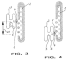
- the Kunststoffgasse 2 is based on an automatic transmission with more than five gears.
- the selector lever 1 can assume the selector positions P, R, N, D_E, 5, 4, 3 and 2 in the shift gate.
- the selector lever can be transferred into the H-shaped shifting gate 3 via the cross alley 4.
- the selector lever can preferably be transferred directly from at least two of its possible selector positions into the shifting gate. In the illustration corresponding to FIG. 3, the selector lever 1 was directly transferred from its selector position D_E in the shift gate 2 into the cross gate 4 of the shift gate 3.
- the shifting gate 3 is preferably locked in place when the selector lever leaves the shift gate. The selector lever can then be transferred to its possible gear shift positions in the usual manner.
- Carrying the shift gate 3 by the selector lever 1 means in the illustrated embodiment of a switching device that the selector lever 1 can be transferred directly from its selector positions D_E, 5, 4, 3 within the shift gate 2 into the shift gate 3.
- a driving program is activated when the selector lever is in a defined area within the H-shaped shift gate 3. This area can correspond to the position in which the selector gate 7 and the shift gate 6 of the H-shaped shift gate 3 intersect.
- the activatable driving program can - at least partially - work according to fuzzy logic methods, neural network technology, analytical strategies or a combination of several strategies using switching points, lines and maps.
Landscapes
- Engineering & Computer Science (AREA)
- General Engineering & Computer Science (AREA)
- Mechanical Engineering (AREA)
- Arrangement Or Mounting Of Control Devices For Change-Speed Gearing (AREA)
- Control Of Transmission Device (AREA)
Applications Claiming Priority (2)
| Application Number | Priority Date | Filing Date | Title |
|---|---|---|---|
| DE4419212A DE4419212A1 (de) | 1994-06-01 | 1994-06-01 | Schaltvorrichtung für ein automatisches Getriebe |
| DE4419212 | 1994-06-01 |
Publications (3)
| Publication Number | Publication Date |
|---|---|
| EP0685664A2 true EP0685664A2 (fr) | 1995-12-06 |
| EP0685664A3 EP0685664A3 (fr) | 1997-07-23 |
| EP0685664B1 EP0685664B1 (fr) | 2001-02-14 |
Family
ID=6519562
Family Applications (1)
| Application Number | Title | Priority Date | Filing Date |
|---|---|---|---|
| EP95108062A Expired - Lifetime EP0685664B1 (fr) | 1994-06-01 | 1995-05-26 | Dispositif de commande de changement de rapport pour transmission automatique |
Country Status (2)
| Country | Link |
|---|---|
| EP (1) | EP0685664B1 (fr) |
| DE (2) | DE4419212A1 (fr) |
Cited By (10)
| Publication number | Priority date | Publication date | Assignee | Title |
|---|---|---|---|---|
| EP0780600A1 (fr) * | 1995-12-20 | 1997-06-25 | Bayerische Motoren Werke Aktiengesellschaft, Patentabteilung AJ-3 | Dispositif de commande pour transmission automatique de véhicule automobile |
| FR2767571A1 (fr) | 1997-08-21 | 1999-02-26 | Siemens Ag | Dispositif de commande d'une boite de vitesses automatique pour vehicule automobile |
| DE19755096A1 (de) * | 1997-12-11 | 1999-06-17 | Volkswagen Ag | Verfahren und Steuervorrichtung zum Steuern eines Automatikgetriebes oder eines automatisierten Schaltgetriebes eines Kraftfahrzeuges |
| WO1999067553A1 (fr) * | 1998-06-12 | 1999-12-29 | Kongsberg Automotive Ab | Dispositif de commande |
| FR2802267A1 (fr) * | 1999-12-08 | 2001-06-15 | Luk Lamellen & Kupplungsbau | Vehicule automobile comportant une boite de vitesses |
| WO2001055622A1 (fr) * | 2000-01-25 | 2001-08-02 | Kongsberg Automotive Asa | Dispositif de commande de changement de vitesse pour vehicules |
| WO2004046286A1 (fr) * | 2002-11-15 | 2004-06-03 | Stepan Company | Melanges de bougies comprenant des esters d'alkyle naturels |
| WO2006131269A1 (fr) * | 2005-06-09 | 2006-12-14 | Zf Friedrichshafen Ag | Systeme de traitement de signal a traitement de signal rapide |
| EP1845288A2 (fr) | 2006-04-10 | 2007-10-17 | Ford Global Technologies, LLC | Procédé et dispositif de sélection de programmes de conduite pour transmission automatique |
| US20170335948A1 (en) * | 2014-11-20 | 2017-11-23 | Audi Ag | Method and device for operating a motor vehicle |
Families Citing this family (8)
| Publication number | Priority date | Publication date | Assignee | Title |
|---|---|---|---|---|
| DE19637533B4 (de) * | 1996-09-14 | 2007-03-22 | Zf Friedrichshafen Ag | Elektrischer Fahrschalter |
| DE19744598B4 (de) * | 1997-10-09 | 2006-06-08 | Volkswagen Ag | Verfahren zum Steuern eines Automatikgetriebes eines Kraftfahrzeuges |
| JP3792586B2 (ja) * | 2002-03-12 | 2006-07-05 | 本田技研工業株式会社 | 車両の変速操作装置 |
| JP4199714B2 (ja) * | 2004-09-02 | 2008-12-17 | 本田技研工業株式会社 | シフト装置及びその制御方法 |
| DE102008030232A1 (de) * | 2008-06-25 | 2009-12-31 | GM Global Technology Operations, Inc., Detroit | Schaltungs-Getriebe-Einheit |
| DE102008044787A1 (de) * | 2008-08-28 | 2010-03-04 | GM Global Technology Operations, Inc., Detroit | Automatisiertes Schaltgetriebeaggregat |
| DE102017203848B4 (de) | 2017-03-08 | 2024-03-14 | Bayerische Motoren Werke Aktiengesellschaft | Bedienelement für ein Fahrzeug mit Automatikgetriebe |
| CN113309850B (zh) * | 2021-05-21 | 2022-06-07 | 福建金汉科技有限公司 | 一种可靠性好的车辆换档装置 |
Citations (5)
| Publication number | Priority date | Publication date | Assignee | Title |
|---|---|---|---|---|
| JPS61157855A (ja) | 1984-12-27 | 1986-07-17 | Nissan Motor Co Ltd | 自動変速機の手動変速装置 |
| DE3717675A1 (de) | 1987-05-26 | 1988-12-08 | Bayerische Motoren Werke Ag | Kraftfahrzeug mit automatischem getriebe |
| DE4042045A1 (de) | 1989-12-28 | 1991-07-04 | Aisin Aw Co | Automatikgetriebe fuer fahrzeuge |
| EP0467773A1 (fr) | 1990-07-17 | 1992-01-22 | Regie Nationale Des Usines Renault S.A. | Dispositif de commande manuelle de boîte de vitesses automatique |
| EP0331797B1 (fr) | 1988-03-10 | 1992-10-21 | Dr.Ing.h.c. F. Porsche Aktiengesellschaft | Dispositif de changement de vitesse pour une transmission automatique d'une automobile |
Family Cites Families (3)
| Publication number | Priority date | Publication date | Assignee | Title |
|---|---|---|---|---|
| US5080207A (en) * | 1987-07-22 | 1992-01-14 | Zahnradfabrik Friedrichshafen Ag | Servo-assisted gear selector |
| DE3832971A1 (de) * | 1988-09-29 | 1990-04-12 | Porsche Ag | Anzeigevorrichtung fuer ein automatisches kraftfahrzeuggetriebe |
| US5415056A (en) * | 1992-09-21 | 1995-05-16 | Toyota Jidosha Kabushiki Kaisha | Shift control system for manually shiftable automatic transmission |
-
1994
- 1994-06-01 DE DE4419212A patent/DE4419212A1/de not_active Withdrawn
-
1995
- 1995-05-26 DE DE59509016T patent/DE59509016D1/de not_active Expired - Fee Related
- 1995-05-26 EP EP95108062A patent/EP0685664B1/fr not_active Expired - Lifetime
Patent Citations (5)
| Publication number | Priority date | Publication date | Assignee | Title |
|---|---|---|---|---|
| JPS61157855A (ja) | 1984-12-27 | 1986-07-17 | Nissan Motor Co Ltd | 自動変速機の手動変速装置 |
| DE3717675A1 (de) | 1987-05-26 | 1988-12-08 | Bayerische Motoren Werke Ag | Kraftfahrzeug mit automatischem getriebe |
| EP0331797B1 (fr) | 1988-03-10 | 1992-10-21 | Dr.Ing.h.c. F. Porsche Aktiengesellschaft | Dispositif de changement de vitesse pour une transmission automatique d'une automobile |
| DE4042045A1 (de) | 1989-12-28 | 1991-07-04 | Aisin Aw Co | Automatikgetriebe fuer fahrzeuge |
| EP0467773A1 (fr) | 1990-07-17 | 1992-01-22 | Regie Nationale Des Usines Renault S.A. | Dispositif de commande manuelle de boîte de vitesses automatique |
Cited By (17)
| Publication number | Priority date | Publication date | Assignee | Title |
|---|---|---|---|---|
| EP0780600A1 (fr) * | 1995-12-20 | 1997-06-25 | Bayerische Motoren Werke Aktiengesellschaft, Patentabteilung AJ-3 | Dispositif de commande pour transmission automatique de véhicule automobile |
| DE19736406B4 (de) * | 1997-08-21 | 2007-05-16 | Siemens Ag | Einrichtung zum Steuern eines automatischen Getriebes für ein Kraftfahrzeug |
| FR2767571A1 (fr) | 1997-08-21 | 1999-02-26 | Siemens Ag | Dispositif de commande d'une boite de vitesses automatique pour vehicule automobile |
| DE19736406A1 (de) * | 1997-08-21 | 1999-03-04 | Siemens Ag | Einrichtung zum Steuern eines automatischen Getriebes für ein Kraftfahrzeug |
| US6035735A (en) * | 1997-08-21 | 2000-03-14 | Siemens Aktiegesellschaft | Device for controlling an automatic transmission of a motor vehicle |
| DE19755096A1 (de) * | 1997-12-11 | 1999-06-17 | Volkswagen Ag | Verfahren und Steuervorrichtung zum Steuern eines Automatikgetriebes oder eines automatisierten Schaltgetriebes eines Kraftfahrzeuges |
| WO1999067553A1 (fr) * | 1998-06-12 | 1999-12-29 | Kongsberg Automotive Ab | Dispositif de commande |
| FR2802267A1 (fr) * | 1999-12-08 | 2001-06-15 | Luk Lamellen & Kupplungsbau | Vehicule automobile comportant une boite de vitesses |
| WO2001055622A1 (fr) * | 2000-01-25 | 2001-08-02 | Kongsberg Automotive Asa | Dispositif de commande de changement de vitesse pour vehicules |
| US6892599B2 (en) | 2000-01-25 | 2005-05-17 | Kongsberg Automotive Asa | Gear shift device for vehicles |
| WO2004046286A1 (fr) * | 2002-11-15 | 2004-06-03 | Stepan Company | Melanges de bougies comprenant des esters d'alkyle naturels |
| WO2006131269A1 (fr) * | 2005-06-09 | 2006-12-14 | Zf Friedrichshafen Ag | Systeme de traitement de signal a traitement de signal rapide |
| US7801655B2 (en) | 2005-06-09 | 2010-09-21 | Zf Friedrichshafen Ag | Signal processing system with rapid signal processing |
| EP1845288A2 (fr) | 2006-04-10 | 2007-10-17 | Ford Global Technologies, LLC | Procédé et dispositif de sélection de programmes de conduite pour transmission automatique |
| EP1845288A3 (fr) * | 2006-04-10 | 2010-02-10 | Ford Global Technologies, LLC | Procédé et dispositif de sélection de programmes de conduite pour transmission automatique |
| US20170335948A1 (en) * | 2014-11-20 | 2017-11-23 | Audi Ag | Method and device for operating a motor vehicle |
| US10527156B2 (en) * | 2014-11-20 | 2020-01-07 | Audi Ag | Method and device for operating a motor vehicle |
Also Published As
| Publication number | Publication date |
|---|---|
| DE59509016D1 (de) | 2001-03-22 |
| EP0685664A3 (fr) | 1997-07-23 |
| DE4419212A1 (de) | 1995-12-07 |
| EP0685664B1 (fr) | 2001-02-14 |
Similar Documents
| Publication | Publication Date | Title |
|---|---|---|
| EP0685664B1 (fr) | Dispositif de commande de changement de rapport pour transmission automatique | |
| EP0444250B1 (fr) | Dispositif de changement de vitesse pour transmission automatique | |
| DE10206985B4 (de) | Getriebeschalteinrichtung | |
| EP1801463B1 (fr) | Dispositif pour changer la vitesse pour une boîte de vitesses | |
| DE3000577C2 (de) | Schalteinrichtung für ein aus einem Haupt- und einem Zweibereichs-Gruppengetriebe bestehenden Zahnräder-Wechselgetriebe | |
| DE3237509A1 (de) | Gangschaltung fuer ein fremdkraftbetaetigtes getriebe | |
| DE102008028619A1 (de) | Schaltvorrichtung für ein Getriebe | |
| DE10052881C2 (de) | Steuervorrichtung für ein Getriebe eines Kraftfahrzeuges | |
| DE19737296C2 (de) | Selbsttätige Schaltvorrichtung eines Gangwechselgetriebes mit einem Handwählorgan | |
| DE102007047120B4 (de) | Schalteinheit für ein insbesondere elektronisch geschaltetes Getriebe eines Kraftfahrzeugs | |
| DE10217614A1 (de) | Bedienelement zum Anwählen von Betriebszuständen eines Getriebes | |
| DE10157393A1 (de) | Verfahren bzw.Vorrichtung zur Steuerung der Schaltungen eines automatischen Getriebes eines Kraftfahrzeuges | |
| DE102005048875B4 (de) | Schalteinheit für ein elektronisch geschaltetes Getriebe eines Kraftfahrzeugs | |
| DE4233938A1 (de) | Schaltvorrichtung für ein durch ein elektronisches Steuergerät gesteuertes automatisches Gebtriebe eines Kraftfahrzeuges | |
| DE3439161A1 (de) | Getriebesteuerung | |
| DE3337930C2 (de) | Wählschalter in einer Schaltsteuerung für Automatgetriebe | |
| DE19756034A1 (de) | Wählvorrichtung für ein Fahrzeuggetriebe | |
| DE4305903A1 (de) | Schaltvorrichtung für ein automatisch schaltendes Kraftfahrzeuggetriebe | |
| EP0999384A1 (fr) | Dispositif de changement de vitesse pour une boíte de vitesse d'un véhicule automobile | |
| DE3228790A1 (de) | Mechanismus fuer ein manuell schaltbares getriebe | |
| EP0771975B1 (fr) | Changement de vitesse pour boíte de vitesses | |
| DE4132346C2 (de) | Steuerung für ein automatisches Getriebe | |
| DE102004060232A1 (de) | Elektrische Schalteinrichtung für ein automatisiertes Getriebe | |
| DE19849076A1 (de) | Wähleinrichtung für ein automatisch geschaltetes Getriebe eines Kraftfahrzeugs | |
| EP0895008B1 (fr) | Méthode de commande de transmission automatique et dispositif de sélection des lois de variation du rapport |
Legal Events
| Date | Code | Title | Description |
|---|---|---|---|
| PUAI | Public reference made under article 153(3) epc to a published international application that has entered the european phase |
Free format text: ORIGINAL CODE: 0009012 |
|
| AK | Designated contracting states |
Kind code of ref document: A2 Designated state(s): DE FR GB IT |
|
| GRAH | Despatch of communication of intention to grant a patent |
Free format text: ORIGINAL CODE: EPIDOS IGRA |
|
| 17P | Request for examination filed |
Effective date: 19960104 |
|
| R17P | Request for examination filed (corrected) |
Effective date: 19951219 |
|
| PUAL | Search report despatched |
Free format text: ORIGINAL CODE: 0009013 |
|
| AK | Designated contracting states |
Kind code of ref document: A3 Designated state(s): DE FR GB IT |
|
| 17Q | First examination report despatched |
Effective date: 19981207 |
|
| GRAG | Despatch of communication of intention to grant |
Free format text: ORIGINAL CODE: EPIDOS AGRA |
|
| GRAG | Despatch of communication of intention to grant |
Free format text: ORIGINAL CODE: EPIDOS AGRA |
|
| GRAH | Despatch of communication of intention to grant a patent |
Free format text: ORIGINAL CODE: EPIDOS IGRA |
|
| GRAH | Despatch of communication of intention to grant a patent |
Free format text: ORIGINAL CODE: EPIDOS IGRA |
|
| GRAA | (expected) grant |
Free format text: ORIGINAL CODE: 0009210 |
|
| AK | Designated contracting states |
Kind code of ref document: B1 Designated state(s): DE FR GB IT |
|
| PG25 | Lapsed in a contracting state [announced via postgrant information from national office to epo] |
Ref country code: IT Free format text: LAPSE BECAUSE OF FAILURE TO SUBMIT A TRANSLATION OF THE DESCRIPTION OR TO PAY THE FEE WITHIN THE PRE;WARNING: LAPSES OF ITALIAN PATENTS WITH EFFECTIVE DATE BEFORE 2007 MAY HAVE OCCURRED AT ANY TIME BEFORE 2007. THE CORRECT EFFECTIVE DATE MAY BE DIFFERENT FROM THE ONE RECORDED.SCRIBED TIME-LIMIT Effective date: 20010214 Ref country code: GB Free format text: LAPSE BECAUSE OF FAILURE TO SUBMIT A TRANSLATION OF THE DESCRIPTION OR TO PAY THE FEE WITHIN THE PRESCRIBED TIME-LIMIT Effective date: 20010214 Ref country code: FR Free format text: LAPSE BECAUSE OF FAILURE TO SUBMIT A TRANSLATION OF THE DESCRIPTION OR TO PAY THE FEE WITHIN THE PRESCRIBED TIME-LIMIT Effective date: 20010214 |
|
| REF | Corresponds to: |
Ref document number: 59509016 Country of ref document: DE Date of ref document: 20010322 |
|
| EN | Fr: translation not filed | ||
| GBV | Gb: ep patent (uk) treated as always having been void in accordance with gb section 77(7)/1977 [no translation filed] |
Effective date: 20010214 |
|
| PLBE | No opposition filed within time limit |
Free format text: ORIGINAL CODE: 0009261 |
|
| STAA | Information on the status of an ep patent application or granted ep patent |
Free format text: STATUS: NO OPPOSITION FILED WITHIN TIME LIMIT |
|
| 26N | No opposition filed | ||
| PG25 | Lapsed in a contracting state [announced via postgrant information from national office to epo] |
Ref country code: DE Free format text: LAPSE BECAUSE OF NON-PAYMENT OF DUE FEES Effective date: 20020301 |