EP0685664A2 - Shift control mechanism for an automatic transmission - Google Patents
Shift control mechanism for an automatic transmission Download PDFInfo
- Publication number
- EP0685664A2 EP0685664A2 EP95108062A EP95108062A EP0685664A2 EP 0685664 A2 EP0685664 A2 EP 0685664A2 EP 95108062 A EP95108062 A EP 95108062A EP 95108062 A EP95108062 A EP 95108062A EP 0685664 A2 EP0685664 A2 EP 0685664A2
- Authority
- EP
- European Patent Office
- Prior art keywords
- gate
- selector
- shift
- selector lever
- switching device
- Prior art date
- Legal status (The legal status is an assumption and is not a legal conclusion. Google has not performed a legal analysis and makes no representation as to the accuracy of the status listed.)
- Granted
Links
Images

Classifications
-
- F—MECHANICAL ENGINEERING; LIGHTING; HEATING; WEAPONS; BLASTING
- F16—ENGINEERING ELEMENTS AND UNITS; GENERAL MEASURES FOR PRODUCING AND MAINTAINING EFFECTIVE FUNCTIONING OF MACHINES OR INSTALLATIONS; THERMAL INSULATION IN GENERAL
- F16H—GEARING
- F16H59/00—Control inputs to control units of change-speed-, or reversing-gearings for conveying rotary motion
- F16H59/02—Selector apparatus
- F16H59/0204—Selector apparatus for automatic transmissions with means for range selection and manual shifting, e.g. range selector with tiptronic
-
- B—PERFORMING OPERATIONS; TRANSPORTING
- B60—VEHICLES IN GENERAL
- B60W—CONJOINT CONTROL OF VEHICLE SUB-UNITS OF DIFFERENT TYPE OR DIFFERENT FUNCTION; CONTROL SYSTEMS SPECIALLY ADAPTED FOR HYBRID VEHICLES; ROAD VEHICLE DRIVE CONTROL SYSTEMS FOR PURPOSES NOT RELATED TO THE CONTROL OF A PARTICULAR SUB-UNIT
- B60W50/00—Details of control systems for road vehicle drive control not related to the control of a particular sub-unit, e.g. process diagnostic or vehicle driver interfaces
- B60W2050/0001—Details of the control system
- B60W2050/0043—Signal treatments, identification of variables or parameters, parameter estimation or state estimation
- B60W2050/0057—Frequency analysis, spectral techniques or transforms
-
- F—MECHANICAL ENGINEERING; LIGHTING; HEATING; WEAPONS; BLASTING
- F16—ENGINEERING ELEMENTS AND UNITS; GENERAL MEASURES FOR PRODUCING AND MAINTAINING EFFECTIVE FUNCTIONING OF MACHINES OR INSTALLATIONS; THERMAL INSULATION IN GENERAL
- F16H—GEARING
- F16H59/00—Control inputs to control units of change-speed-, or reversing-gearings for conveying rotary motion
- F16H2059/006—Overriding automatic control
-
- F—MECHANICAL ENGINEERING; LIGHTING; HEATING; WEAPONS; BLASTING
- F16—ENGINEERING ELEMENTS AND UNITS; GENERAL MEASURES FOR PRODUCING AND MAINTAINING EFFECTIVE FUNCTIONING OF MACHINES OR INSTALLATIONS; THERMAL INSULATION IN GENERAL
- F16H—GEARING
- F16H59/00—Control inputs to control units of change-speed-, or reversing-gearings for conveying rotary motion
- F16H59/02—Selector apparatus
- F16H59/08—Range selector apparatus
- F16H2059/082—Range selector apparatus with different modes
- F16H2059/084—Economy mode
-
- F—MECHANICAL ENGINEERING; LIGHTING; HEATING; WEAPONS; BLASTING
- F16—ENGINEERING ELEMENTS AND UNITS; GENERAL MEASURES FOR PRODUCING AND MAINTAINING EFFECTIVE FUNCTIONING OF MACHINES OR INSTALLATIONS; THERMAL INSULATION IN GENERAL
- F16H—GEARING
- F16H59/00—Control inputs to control units of change-speed-, or reversing-gearings for conveying rotary motion
- F16H59/02—Selector apparatus
- F16H59/08—Range selector apparatus
- F16H2059/082—Range selector apparatus with different modes
- F16H2059/085—Power mode
-
- F—MECHANICAL ENGINEERING; LIGHTING; HEATING; WEAPONS; BLASTING
- F16—ENGINEERING ELEMENTS AND UNITS; GENERAL MEASURES FOR PRODUCING AND MAINTAINING EFFECTIVE FUNCTIONING OF MACHINES OR INSTALLATIONS; THERMAL INSULATION IN GENERAL
- F16H—GEARING
- F16H59/00—Control inputs to control units of change-speed-, or reversing-gearings for conveying rotary motion
- F16H59/02—Selector apparatus
- F16H59/08—Range selector apparatus
- F16H2059/082—Range selector apparatus with different modes
- F16H2059/086—Adaptive mode, e.g. learning from the driver
-
- F—MECHANICAL ENGINEERING; LIGHTING; HEATING; WEAPONS; BLASTING
- F16—ENGINEERING ELEMENTS AND UNITS; GENERAL MEASURES FOR PRODUCING AND MAINTAINING EFFECTIVE FUNCTIONING OF MACHINES OR INSTALLATIONS; THERMAL INSULATION IN GENERAL
- F16H—GEARING
- F16H61/00—Control functions within control units of change-speed- or reversing-gearings for conveying rotary motion ; Control of exclusively fluid gearing, friction gearing, gearings with endless flexible members or other particular types of gearing
- F16H2061/0075—Control functions within control units of change-speed- or reversing-gearings for conveying rotary motion ; Control of exclusively fluid gearing, friction gearing, gearings with endless flexible members or other particular types of gearing characterised by a particular control method
- F16H2061/0081—Fuzzy logic
-
- F—MECHANICAL ENGINEERING; LIGHTING; HEATING; WEAPONS; BLASTING
- F16—ENGINEERING ELEMENTS AND UNITS; GENERAL MEASURES FOR PRODUCING AND MAINTAINING EFFECTIVE FUNCTIONING OF MACHINES OR INSTALLATIONS; THERMAL INSULATION IN GENERAL
- F16H—GEARING
- F16H61/00—Control functions within control units of change-speed- or reversing-gearings for conveying rotary motion ; Control of exclusively fluid gearing, friction gearing, gearings with endless flexible members or other particular types of gearing
- F16H2061/0075—Control functions within control units of change-speed- or reversing-gearings for conveying rotary motion ; Control of exclusively fluid gearing, friction gearing, gearings with endless flexible members or other particular types of gearing characterised by a particular control method
- F16H2061/0096—Control functions within control units of change-speed- or reversing-gearings for conveying rotary motion ; Control of exclusively fluid gearing, friction gearing, gearings with endless flexible members or other particular types of gearing characterised by a particular control method using a parameter map
-
- F—MECHANICAL ENGINEERING; LIGHTING; HEATING; WEAPONS; BLASTING
- F16—ENGINEERING ELEMENTS AND UNITS; GENERAL MEASURES FOR PRODUCING AND MAINTAINING EFFECTIVE FUNCTIONING OF MACHINES OR INSTALLATIONS; THERMAL INSULATION IN GENERAL
- F16H—GEARING
- F16H59/00—Control inputs to control units of change-speed-, or reversing-gearings for conveying rotary motion
- F16H59/02—Selector apparatus
- F16H59/08—Range selector apparatus
- F16H59/10—Range selector apparatus comprising levers
Abstract
Description
Die Erfindung bezieht sich auf eine Schaltvorrichtung für ein automatisches Getriebe eines Kraftfahrzeugs, mit einem Wählhebel, der in einer ersten Schaltgasse verschwenkbar ist, um die automatisch zu schaltenden Getriebegänge vorzuwählen und der über eine Quergasse in eine H-förmige Schaltkulisse mit einer Wählgasse und weiteren Schaltgassen überführt werden kann, um die Gänge des Getriebes manuell zu schalten.The invention relates to a switching device for an automatic transmission of a motor vehicle, with a selector lever which can be pivoted in a first shift gate in order to preselect the automatically shiftable transmission gears and which via a cross gate in an H-shaped shift gate with a select gate and further shift gates can be transferred to shift the gears of the transmission manually.
Aus der DE-A 37 17 675 ist eine Schaltvorrichtung für ein automatisches Getriebe bekanntgeworden, bei der der Wählhebel in zwei Schaltgassen verschwenkt werden kann. In einer ersten Schaltgasse sind die Wählstellungen P, R, N, D, 3, 2, 1 vorwählbar. Der Wählhebel kann über eine Quergasse in die zweite Schaltgasse überführt werden. Durch Längsverschwenken in dieser Schaltgasse sind die einzelnen Gänge des Getriebes manuell zu schalten. Eine vergleichbare Schaltvorrichtung ist aus der EP-B 0 331 797 ebenfalls bekannt.From DE-A 37 17 675 a switching device for an automatic transmission has become known, in which the selector lever can be pivoted in two shift gates. The selection positions P, R, N, D, 3, 2, 1 can be preselected in a first shift gate. The selector lever can be transferred to the second shift gate via a cross gate. The individual gears of the transmission can be shifted manually by swiveling longitudinally in this shift gate. A comparable switching device is also known from EP-B 0 331 797.
Bei dem bekannten Vorschlag nach der EP-A 0 467 773 ist eine einzige Schaltgasse für die Positionen P (Parken), R (Rückwärts), N (Neutral), D (Drive), M (Manuell) und eine HochSchaltbegrenzungs-Automatikstufe 1 vorgesehen. Befindet sich der Wählhebel in seiner M-Wählposition, sind die Gänge des Getriebes durch Verschwenken des Wählhebels quer zur Schaltgasse manuell schaltbar.In the known proposal according to EP-A 0 467 773, a single shift gate is provided for the positions P (park), R (reverse), N (neutral), D (drive), M (manual) and an upshift limitation
Bei den vorstehend erläuterten Lösungen ist nachteilig, daß die absolute Gangposition nach mehreren manuellen Schaltungen (Tipp-Bewegungen) dem Fahrer nicht mehr bekannt ist. Um diesem Nachteil zu begegnen, ist eine visuelle Anzeige erforderlich. Ferner wird dem Fahrer kein haptisches Signal bei einer durchgeführten Gangschaltung vermittelt.In the solutions explained above, it is disadvantageous that the absolute gear position is no longer known to the driver after several manual shifts (jog movements). To counter this disadvantage is a visual display required. Furthermore, the driver is not given a haptic signal when the gear is shifted.
Aus der JP-A 61-157855 ist eine Schaltvorrichtung für ein automatisches Getriebe bekannt, bei der der Schaltgasse zur Vorwahl der automatisch zu schaltenden Getriebegänge bzw. Fahrprogramme eine weitere Schaltkulisse zugeordnet ist. Diese Schaltkulisse ist H-förmig ausgebildet und bietet daher dem Fahrer das ihm von Handschaltgetrieben her gewohnte Bild. Für den Fahrer hat dies den Vorteil, daß er beim Wechsel von einem Fahrzeug mit Handschaltgetriebe auf ein Fahrzeug mit einem Automatgetriebe keine Umstellungsschwierigkeiten hat. Trotz dieses Vorteils geht diese bekannte Lösung über eine Aggregation einer Schaltgasse zur Anwahl der Automatik-Funktionen mit einer Schaltkulisse zur manuellen Gangwahl nicht hinaus.A switching device for an automatic transmission is known from JP-A 61-157855, in which a further shifting gate is assigned to the shift gate for preselecting the transmission gears or driving programs to be switched automatically. This shifting gate is H-shaped and therefore offers the driver the image he is used to from manual transmissions. For the driver, this has the advantage that when changing from a vehicle with a manual transmission to a vehicle with an automatic transmission, there is no changeover problem. Despite this advantage, this known solution does not go beyond aggregating a shift gate for selecting the automatic functions with a shift gate for manual gear selection.
Der vorliegenden Erfindung liegt die Aufgabe zugrunde, eine Schaltvorrichtung für ein automatisches Getriebe der eingangs genannten Art so auszubilden, daß bei der Verbindung einer Schaltgasse zur Vorwahl der Automatik-Funktionen mit einer Schaltkulisse zur manuellen Gangschaltung zusätzliche Synergieeffekte erzielt werden.The present invention has for its object to provide a switching device for an automatic transmission of the type mentioned so that additional synergy effects are achieved when connecting a shift gate for preselecting the automatic functions with a shift gate for manual gear shifting.
Die der Erfindung zugrunde liegende Aufgabe wird dadurch gelöst, daß in einer Stellung des Wählhebels innerhalb der H-förmigen Schaltkulisse ein Signal generiert wird, durch das ein (weiteres) Fahrprogramm aktiviert wird. Diese Stellung entspricht dem Bereich, in dem sich die Wählgasse und eine Schaltgasse der H-förmigen Schaltkulisse kreuzen. Durch die vorgeschlagene Lösung wird dem Fachmann der entscheidende Hinweis gegeben, wie eine funktionelle Verschmelzung einer Wählgasse für Automatik-Funktionen mit einer Schaltkulisse für die Manuell-Funktionen erfolgen kann. Die Lösung erschöpft sich demnach nicht in der bloßen Aggregation einer Wählgasse und einer H-förmigen Schaltkulisse.The object on which the invention is based is achieved in that, when the selector lever is in a position within the H-shaped shifting gate, a signal is generated by which a (further) driving program is activated. This position corresponds to the area in which the selector gate and a shift gate of the H-shaped shift gate intersect. The proposed solution gives the person skilled in the art decisive information on how a functional fusion of a selection gate for automatic functions can take place with a shift gate for the manual functions. The solution is therefore not limited to the mere one Aggregation of a dialing lane and an H-shaped shifting gate.
Bei einem bevorzugten Ausführungsbeispiel handelt es sich bei dem aktivierten Fahrprogramm um ein Fahrprogramm, bei dem alle Gänge bei einer leistungsorientierten Fahrweise zur Verfügung stehen. In der ersten Schaltgasse liegen die Automatik-üblichen Wählstellungen P, R, N und D_E. An diese Schaltgasse schließt sich die Schaltkulisse vorzugsweise so an, daß sich die Fahrprogramme D_E und D_S gegenüberliegen. Ihre räumliche Lage ist durch eine Quergasse getrennt.In a preferred exemplary embodiment, the activated driving program is a driving program in which all gears are available in a performance-oriented driving style. The automatic selector positions P, R, N and D_E are in the first shift gate. The shift gate preferably adjoins this shift gate in such a way that the driving programs D_E and D_S are opposite one another. Their spatial location is separated by a cross alley.
Es hat sich als vorteilhaft erwiesen, den Wählhebel im Kreuzungsbereich der Wählgasse und der Schaltgasse federnd zu zentrieren. Durch diese Maßnahme wird der Wählhebel, nachdem er vom Fahrer losgelassen wurde, regelmäßig in eine Ausgangsstellung innerhalb der Schaltkulisse zurückgeführt.It has proven to be advantageous to resiliently center the selector lever in the intersection area of the selector gate and the shift gate. With this measure, the selector lever, after being released by the driver, is regularly returned to an initial position within the shifting gate.
Es ist vorteilhaft, wenn der Wählhebel zur manuellen Schaltung eines Ganges ein Gangschaltsignal generiert, das von einem elektronischen Steuergerät auf Zulässigkeit bzw. Plausibilität überprüft und weiterverarbeitet wird. So besteht eine vorteilhafte Möglichkeit darin, das generierte Gangschaltsignal nur dann zu akzeptieren, sofern der angewählte Gang in einem zulässigen Drehzahlbereich liegt.It is advantageous if the selector lever for manual gear shifting generates a gear shift signal which is checked and further processed by an electronic control device for admissibility or plausibility. An advantageous possibility is to only accept the generated gearshift signal if the selected gear is in a permissible speed range.
Ein besonders gutes Schaltgefühl läßt sich dem Fahrer dann vermitteln, wenn ein akzeptiertes Gangschaltsignal dem Fahrer haptisch mitgeteilt wird. Es hat sich als sehr elegant erwiesen, wenn bei einem nicht akzeptierten Gangschaltsignal der Wählhebel in seine Ausgangsstellung D_S selbsttätig zurückgeführt wird.A particularly good shift feeling can be conveyed to the driver when an accepted gear shift signal is communicated to the driver by haptic. It has proven to be very elegant if the selector lever is automatically returned to its starting position D_S in the event of an unaccepted gearshift signal.
Eine Möglichkeit, ein haptisches Signal zu erzeugen, besteht im Verrasten des Wählhebels in der jeweils angewählten Gangschaltstellung.One way of generating a haptic signal is to lock the selector lever in the gear position selected.
Bei einer weiteren Ausgestaltung der Schaltvorrichtung wird ein manuell geschalteter Gang bei untertouriger Fahrweise selbsttätig gelöst. Der Wählhebel wird entrastet und in seine Ausgangsstellung D_S zurückgeführt. Anschließend wird das Fahrprogramm D_S aktiviert, das selbsttätig eine gebotene Rückschaltung ausführt.In a further embodiment of the shifting device, a manually shifted gear is automatically released in the case of a low-speed driving style. The selector lever is released and returned to its starting position D_S. Then the driving program D_S is activated, which automatically performs a downshift.
Um Fehlfunktionen auszuschalten, ist es besonders vorteilhaft, ein Zeitfenster zu aktivieren, wenn der Wählhebel die Wählstellung D_S erreicht. Das Fahrprogramm D_S wird erst nach Ablauf eines vorgebbaren Zeitintervalls aktiviert. Andererseits wird das Fahrprogramm D_S durch das aktivierte Zeitfenster nicht aufgerufen, wenn der Wählhebel lediglich die Wählstellung D_S überfährt.In order to eliminate malfunctions, it is particularly advantageous to activate a time window when the selector lever reaches the selector position D_S. The driving program D_S is only activated after a predefinable time interval. On the other hand, the travel program D_S is not called up by the activated time window if the selector lever only moves over the selected position D_S.
Die vorgeschlagene Schaltvorrichtung kann selbstverständlich weitere Abwandlungen erfahren, ohne daß hierbei der Kern der Erfindung verlassen wird. Beispielsweise kann das Fahrprogramm D_S adaptiv, d. h. selbstlernend, ausgebildet sein, so daß dem jeweiligen Fahrertyp Rechnung getragen wird.The proposed switching device can of course undergo further modifications without leaving the core of the invention. For example, the driving program D_S can be adaptive, i. H. be self-learning, trained so that the respective driver type is taken into account.
Zur manuellen Schaltung der verfügbaren Gänge ist die Verrastung des Wählhebels durch Handkraft außer Funktion zu bringen.To switch the available gears manually, the locking of the selector lever must be disabled by hand.
Bei einer weiteren Lösung der der Erfindung zugrunde liegenden Aufgabe kann der Wählhebel aus mindestens zwei seiner möglichen Wählstellungen in der ersten Schaltgasse direkt in die Schaltkulisse überführt werden. Bei dieser Lösung ist die Verbindung einer Schaltgasse zur Vorwahl der Automatik-Funktionen mit einer Schaltkulisse zur manuellen Gangschaltung besonders elegant gelöst. Die Schaltkulisse wird mit dem Wählhebel, solange er sich in der Schaltgasse befindet, mitgeführt. Auf diese Weise wird sichergestellt, daß der Wählhebel aus jeder seiner möglichen Positionen innerhalb der Schaltgasse direkt in die Schaltkulisse überführt werden kann. Dies ist vor allem deshalb wichtig, weil der Fahrer beispielsweise in der Wählstellung 4 oder 3 oder 2 feststellen kann, daß die Hochschaltbegrenzung nicht ausreichend ist und ein schneller Wechsel in die Schaltkulisse zum manuellen Schalten der Gänge erforderlich bzw. wünschenswert ist. Müßte der Fahrer über die Wählstellung D aus der Schaltgasse in die Schaltkulisse wechseln, wäre dies, neben einem Zeitverlust, mit einer zusätzlichen Konzentration auf diesen Vorgang verbunden. Die Schaltkulisse wird beim Wechsel des Wählhebels aus der Schaltgasse in die Schaltkulisse selbsttätig arretiert, so daß sich die Gänge in der gewohnten Weise manuell schalten lassen. Auch bei dieser Lösung kann ein zusätzliches Fahrprogramm aktiviert werden, wenn sich der Wählhebel in einer definierten Stellung innerhalb der H-förmigen Schaltkulisse befindet.In a further solution to the object on which the invention is based, the selector lever can be transferred directly from at least two of its possible selector positions in the first shift gate into the shift gate. In this solution, the connection of a shift gate to the preselection of Automatic functions with a shift gate for manual gear shifting are particularly elegantly solved. The shift gate is carried along with the selector lever as long as it is in the shift gate. In this way it is ensured that the selector lever can be transferred directly into the shifting gate from any of its possible positions within the shift gate. This is particularly important because the driver can determine, for example in
Die vorgeschlagenen Lösungen lassen sich auch bei einem automatischen Getriebe mit mehr als fünf Gängen einsetzen. In Frage kommt vor allem die Anwendung bei einem 6-Gang-Pkw-Getriebe oder einem Bus-Getriebe mit 8 Gängen.The proposed solutions can also be used in an automatic transmission with more than five gears. Above all, the application in a 6-speed car transmission or a bus transmission with 8 gears comes into question.
Das Fahrprogramm, das aktiviert wird, wenn sich der Wählhebel in einer definierten Stellung innerhalb der H-förmigen Schaltkulisse befindet, kann nach beliebigen Strategien arbeiten. Dieses Fahrprogramm kann - zumindest teilweise - nach Fuzzy-Logik-Methoden, nach neuronaler Netz-Technik, nach analytischen Strategien oder nach einer Kombination mehrerer Strategien unter Verwendung von Schaltpunkten, -linien und -kennfeldern arbeiten.The drive program, which is activated when the selector lever is in a defined position within the H-shaped shift gate, can work according to any strategy. This driving program can - at least in part - work according to fuzzy logic methods, according to neural network technology, according to analytical strategies or according to a combination of several strategies using switching points, lines and maps.
Die mit der Erfindung erzielbaren Vorteile bestehen zusammenfassend darin, daß durch die vorgeschlagene Kombination der Automatik-Schaltgasse und der Manuell-Schaltkulisse eine funktionelle Verschmelzung der Automatik- und Manuell-Funktionen erreicht wird.In summary, the advantages that can be achieved with the invention consist in that the proposed combination of the automatic shift gate and the manual shift gate achieves a functional fusion of the automatic and manual functions.
Weitere, für die Erfindung wesentliche Merkmale sowie die hieraus resultierenden Vorteile sind der nachfolgenden Beschreibung zweier Ausführungsbeispiele unter Bezugnahme auf die Zeichnungen näher erläutert. Es zeigen:
- Fig. 1
- eine schematische Ansicht einer Schaltvorrichtung mit einem Wählhebel;
- Fig. 2
- eine Einzelheit der Schaltvorrichtung nach Fig. 1 in ebenfalls stark vereinfachter, schematischer Darstellung;
- Fig. 3
- eine schematische Ansicht einer weiteren Schaltvorrichtung mit einem Wählhebel entsprechend einer ersten Fahrsituation und
- Fig. 4
- die Ansicht der Schaltvorrichtung nach Fig. 3 in einer weiteren Fahrsituation.
- Fig. 1
- a schematic view of a switching device with a selector lever;
- Fig. 2
- a detail of the switching device of Figure 1 also in a greatly simplified, schematic representation.
- Fig. 3
- a schematic view of another switching device with a selector lever according to a first driving situation and
- Fig. 4
- the view of the switching device of FIG. 3 in a further driving situation.
Eine erste Ausführungsform der Erfindung wird im folgenden am Beispiel eines elektrohydraulisch gesteuerten, automatischen 4-Gang-Getriebes mit den Programmen "Drive_ Economy, D_E" und den Schaltstellungen N (Neutral), R (Rückwärts) und P (Parken) näher erläuert.A first embodiment of the invention is explained in more detail below using the example of an electrohydraulically controlled, automatic 4-speed transmission with the programs "Drive_ Economy, D_E" and the shift positions N (neutral), R (reverse) and P (park).
In Fig. 1 ist ein Wählhebel 1 mit einem kreisförmigen Querschnitt schraffiert abgebildet. Der Wählhebel 1 ist um einen nicht eingezeichneten Drehpunkt kardangelenkartig schwenkbar abgestützt und kann vom Fahrer in einer ersten Schaltgasse 2 verschwenkt werden. An die erste Schaltgasse 2 schließt sich eine H-förmige Schaltkulisse 3 an.In Fig. 1, a
In der ersten Schaltgasse 2, der Automatik-Schaltgasse, ist die Anordnung der einzelnen Wählhebel-Positionen Automatik-üblich. Diese Schaltgasse enthält die Schaltpositionen P, R, N und D_E (Fahrprogramm bei verbrauchsorientierter Fahrweise).In the
Die Schaltgasse 2 kann ferner um die Automatik-üblichen Schaltpositionen 3, 2 und 1 ergänzt werden. Hier werden die möglichen Hochschaltungen begrenzt bzw. nicht zugelassen, wobei in der Position 1 die Kupplung für die Kraftübertragung bei Schubbetrieb im ersten Gang geschlossen wird.The
Der Wählhebel 1 ist aus der Schaltgasse 2 aus der Schaltposition bzw. Programmwahl D_E über eine Quergasse 4 in die H-förmige Schaltkulisse 3 überführbar.The
Die H-förmige Schaltkulisse 3 setzt sich aus zwei weiteren Schaltgassen 5 und 6, die über eine Wählgasse 7 miteinander verbunden sind, zusammen. Die Schaltkulisse 3 bietet dem Fahrer ein von einem viergängigen Handschaltgetriebe her gewohntes Bild. Selbstverständlich kann die Schaltkulisse 3 bedarfsweise um eine Gasse für mindestens einen weiteren Gang, so zum Beispiel einen fünften Gang, erweitert werden.The H-shaped
In der Schaltgasse 5 liegen sich die manuell zu schaltenden Gänge 1 und 2 und in der Schaltgasse 6 die Gänge 3 und 4 diametral gegenüber.In the
Wenn der Fahrer über den Wählhebel eine der mit I bis IV gekennzeichneten Gangschaltstellungen anwählt, wird der entsprechende Gang 1, 2, 3 oder 4 eingelegt. Hierzu wird ein diesem Gang zugeordneter elektrischer Schalter S1, S2, S3 oder S4 geschlossen. Es wird ein Gangschaltsignal generiert, das an ein selbst nicht dargestelltes elektronisches Steuergerät (EGS) weitergeleitet wird. Es ist zweckmäßig, die elektronische Steuerung so auszubilden, daß dieses Gangschaltsignal nur dann akzeptiert wird, sofern der angewählte Gang im erlaubten Drehzahlbereich liegt.When the driver selects one of the gear shift positions marked I to IV using the selector lever, the
Der Vollständigkeit halber sei erwähnt, daß der Wählhebel 1 gegen die Kraft von Federn F in die Gangschaltstellungen überführt wird. Diese Federn F besorgen auch die Rückstellung des Wählhebels 1 in eine Ausgangslage - innerhalb der Schaltkulisse 3 -, sofern der Wählhebel 1 nicht verriegelt ist und vom Fahrer losgelassen, d. h. keine Handkraft ausgeübt, wird. Auf diese Ausgangslage wird weiter unten näher eingegangen.For the sake of completeness, it should be mentioned that the
Die Federn F, deren Wirkungsrichtungen in Längsrichtung der Schaltgassen 5 und 6 verlaufen, werden durch mindestens eine weitere, seitlich angeordnete Feder F ergänzt, um die erwähnte Ausgangslage des Wählhebels 1 in der Schaltkulisse 3 sicherzustellen. Die Wirkungsrichtung dieser weiteren Feder F verläuft gleichgerichtet zur Richtung der Wählgasse 7. Bei den Federn F kann es sich um Zug- und/oder Druckfedern handeln. Anstelle der vorgeschlagenen Federn können gleichwirkende, elastische Elemente eingesetzt werden, die sicherstellen, daß der Wählhebel 1 in eine bestimmte Ausgangslage innerhalb der Schaltkulisse 3 überführt wird.The springs F, whose directions of action run in the longitudinal direction of the
Zwei schematisch angedeutete Riegelmagnete 8 und 9 besorgen die Verrastung (Sicherung) des Wählhebels 1 in seinen möglichen Gangschaltstellungen. Es hat sich als ausreichend erwiesen, jeweils einen Riegelmagneten 8 bzw. 9 für die Gangschaltstellungen I und III bzw. II und IV vorzusehen. Selbstverständlich sind andere elektro-mechanisch oder hydraulisch wirkende Bauteile verwendbar, die eine Verriegelung des Wählhebels 1 in den erwähnten Gangschaltstellungen sicherstellen.Two schematically indicated locking
Wird einer der verfügbaren Gänge vom Fahrer angewählt und liegt dieser angewählte Gang im erlaubten Drehzahlbereich, wird das generierte Gangschaltsignal durch die Verrastung des Wählhebels 1 quittiert. Durch die Riegelmagnete oder andere geeignete Mittel wird nicht nur diese Verrastung sichergestellt. Durch diesen Vorgang wird dem Fahrer vielmehr auch ein haptisches Signal übermittelt. Hiermit kann ein sehr gutes Schaltgefühl realisiert werden.If one of the available gears is selected by the driver and this selected gear is within the permitted speed range, the generated gearshift signal is acknowledged by locking
Für den Fall, daß ein Gangschaltsignal nicht akzeptiert wird, hat es sich als sehr vorteilhaft erwiesen, den Wählhebel 1 nicht zu verriegeln, sondern die Rückstellkräfte der Federn F wirken zu lassen. Durch diese Rückstellkräfte wird der Wählhebel, nachdem er vom Fahrer losgelassen wurde, in die erwähnte Ausgangsstellung in der Schaltkulisse 3 zurückgeführt.In the event that a gear shift signal is not accepted, it has proven to be very advantageous not to lock the
Bei einer möglichen Ausführungsform der Schaltvorrichtung hat sich folgende Funktion bewährt: Bei einer untertourigen Fahrweise in einem manuell geschalteten Gang wird über das elektronische Steuergerät eine Entriegelung des Wählhebels 1 ausgelöst. Dann wird der Wählhebel beim Unterschreiten einer unteren Drehzahlgrenze selbsttätig in die Ausgangsstellung innerhalb der Schaltkulisse 3 zurückgeführt. An diese Aktion kann sich ein weiterer Schritt, wie unten ausgeführt, anschließen.The following function has proven itself in a possible embodiment of the shifting device: in the case of a low-speed driving style in a manually shifted gear, the electronic control unit releases the
Die in Fig. 1 eingezeichneten Pfeile 10, 11, 12 und 13 verdeutlichen die Rückführung des Wählhebels 1 in seine Ausgangslage in der Schaltkulisse 3.The
Ein wesentliches Merkmal der vorliegenden Erfindung besteht nun darin, daß dem Bereich, in dem sich die Schaltgasse 6 der Gänge 3 und 4 mit der Wählgasse 7 bzw. der Quergasse 4 kreuzen, eine weitere Funktion des automatischen Getriebes zugeordnet ist. In dieser Schaltposition wird ein weiteres Fahrprogramm aufgerufen. Dieses Fahrprogramm kann an sich ebenfalls Automatik-üblich sein.An essential feature of the present invention is that a further function of the automatic transmission is assigned to the area in which the
Die Besonderheit besteht nun aber auch darin, daß dieses an sich Automatik-übliche Fahrprogramm nicht der Schaltgasse 2, also der Automatik-Schaltgasse, zugeordnet ist. Diese Schaltposition bzw. dieses Fahrprogramm ist in einen Bereich der Schaltkulisse 3, also der Manuell-Schaltkulisse, verlagert. Hiermit läßt sich eine funktionelle Verschmelzung der Automatik- und Manuell-Funktionen erreichen, weil diese Schaltposition bzw. dieses Fahrprogramm sowohl von der Schaltgasse 2 als auch von der Schaltkulisse 3 aus (hier unter den gegebenen Voraussetzungen auch selbsttätig) erreichbar ist.The peculiarity now also consists in the fact that this driving program, which in itself is automatic, is not assigned to shift
Die mehrfach erwähnte Ausgangslage des Wählhebels 1 innerhalb der Schaltkulisse 3 entspricht dieser zusätzlichen Schaltposition, so daß demnach der Wählhebel 1 ohne äußere Einwirkung in dieser Ausgangslage im Kreuzungsbereich der Wählgasse 7 und der Schaltgasse 6 federnd zentriert ist.The starting position of the
In der Abbildung nach Fig. 1 ist die zusätzliche Schaltposition in der H-förmigen Schaltkulisse 3 mit D_S gekennzeichnet. Bei dem zugehörigen Fahrprogramm handelt es sich um ein Fahrprogramm, bei dem sämtliche Gänge des automatischen Getriebes zur Verfügung stehen und das auf eine leistungsorientierte (sportliche) Fahrweise abgestimmt ist. Die Fahrprogramme D_E (Schaltgasse 2) und D_S liegen sich gegenüber, so daß ein Fahrprogrammwechsel immer von D_E nach D_S bzw. umgekehrt erfolgt.1, the additional shift position in the H-shaped
Dieses Fahrprogramm D_S kann auch - je nach Fahrverhalten des Fahrers - adaptiv generiert werden.This driving program D_S can also be generated adaptively, depending on the driving behavior of the driver.
Die vorstehend erläuterte Schaltvorrichtung ist für den Fahrer in mehrfacher Hinsicht von großem Vorteil: Einerseits ist ein gezielter Eingriff des Fahrers zur manuellen Gangwahl möglich. Der Fahrer kann auf besondere Straßenführungen oder besondere Verkehrssituationen intuitiv und effektiv reagieren. Andererseits kommt die atypische Positionierung des zusätzlichen Fahrprogramms D_S in der Schaltkulisse 3 den Intentionen des Fahrers entgegen, wenn dieser aus der Schaltgasse 2, die den Automatik-Funktionen vorbehalten ist, in die Schaltkulisse zur manuellen Gangwahl wechselt: Selbst wenn der Fahrer von der gegebenen Möglichkeit einer manuellen Gangwahl keinen Gebrauch macht, ist eine leistungsorientierte Fahrweise (die ja in den meisten Fällen der Auslöser für eine gewünschte manuelle Gangwahl ist) dennoch gegeben. Insofern ist die vorgeschlagene Lösung keine bloße Addition einer Schaltgasse mit Automatik-Funktionen und einer H-förmigen Schaltkulisse zur manuellen Gangwahl.The shifting device explained above is of great advantage to the driver in several respects: on the one hand, the driver can selectively intervene to select a manual gear. The driver can react intuitively and effectively to special road layouts or special traffic situations. On the other hand, the atypical positioning of the additional driving program D_S in the
Wenn, wie oben erwähnt, in einem manuell geschalteten Gang eine untere Drehzahlgrenze unterschritten wird, besteht der besagte, sich an die selbsttätig ablaufende Entriegelung des Wählhebels anschließende weitere Schritt darin, daß der Wählhebel in die Ausgangsstellung D_S zurückgeführt wird. Das Fahrprogramm D_S wird aktiviert und es erfolgt eine Rückschaltung.If, as mentioned above, a lower speed limit is undershot in a manually shifted gear, the said further step, which follows the automatic release of the selector lever, is that the selector lever is returned to the starting position D_S. The drive program D_S is activated and a downshift takes place.
In Fig. 2 ist eine Möglichkeit zur Verriegelung des Wählhebels 1 schematisch angedeutet. In eine Nockenbahn 14 des Wählhebels 1 sind Kerben 15 und 16 eingearbeitet. Diese können beispielsweise dem dritten und vierten Gang zugeordnet sein. Ein zweiarmiger Winkelhebel 17 trägt an seinem freien Ende eine Rastkugel 18. Das andere Ende ist - unter Zwischenschaltung einer Druckfeder 19 - mit dem Riegelmagnet 8 bzw. 9 verbunden. Die schematisch angedeutete Verriegelungseinrichtung stellt eine Verriegelung bzw. Verrastung des Wählhebels 1 in einer der möglichen Gangschaltstellungen sicher. Andererseits ist diese Verrastung bei einem Gangwechsel durch Überwinden der Kraft der Druckfeder 19 überdrückbar.A possibility for locking the
Es ist schließlich vorteilhaft, ein Zeitfenster zu aktivieren, wenn der Wählhebel 1 seine Ausgangsstellung in der Schaltkulisse 3, d. h. die Wählstellung D_S, erreicht. Dieses Fahrprogramm wird sodann nach Ablauf eines vorgebbaren Zeitraums (zum Beispiel 0,2 sec) aktiviert. Der Aufruf des Fahrprogramms D_S unterbleibt jedoch, wenn der Wählhebel 1 die Wählstellung innerhalb dieses Zeitintervalls lediglich überfährt.Finally, it is advantageous to activate a time window when the
Sofern es sich bei der Schaltkulisse um eine solche für fünf oder mehr manuell schaltbare Gänge handelt, ist es vorteilhaft, die vorgeschlagene Ausgangsstellung des Wählhebels 1 im Kreuzungsbereich der Schaltgasse 6 und der Wählgasse 7 beizubehalten. Somit wird dann beim Verlassen der Schaltstellung für den fünften Gang ebenfalls das Fahrprogramm D_S aktiviert, sofern nicht ein anderer Gang manuell geschaltet wird.If the shifting gate is one for five or more manually shiftable gears, it is advantageous to maintain the proposed starting position of the
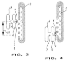
Die Fig. 3 zeigt ein weiteres Ausführungsbeispiel einer erfindungsgemäßen Schaltvorrichtung. Der Schaltgasse 2 liegt ein automatisches Getriebe mit mehr als fünf Gängen zugrunde. Der Wählhebel 1 kann in der Schaltgasse die Wählstellungen P, R, N, D_E, 5, 4, 3 und 2 einnehmen. Über die Quergasse 4 kann der Wählhebel in die H-förmige Schaltkulisse 3 überführt werden.3 shows a further exemplary embodiment of a switching device according to the invention. The
Der konstruktive Aufbau der Schaltkulisse 3 und die zur manuellen Gangschaltung erforderlichen Bauteile entsprechen im übrigen der H-förmigen Schaltkulisse, wie sie im Zusammenhang in den Fig. 1 und 2 näher erläutert wurde. Um Wiederholungen zu vermeiden, wird auf die dort gemachten Ausführungen verwiesen.The structural design of the
Die Schaltkulisse 3 ist, was durch einen Doppelpfeil 20 hervorgehoben ist, in bezug auf die Schaltgasse 2 verschiebbar angeordnet. Solange sich der Wählhebel 1 innerhalb der Schaltgasse 2 befindet, wird die Schaltkulisse 3 mitgeführt. Vorzugsweise ist der Wählhebel aus mindestens zwei seiner möglichen Wählstellungen direkt in die Schaltkulisse überführbar. Bei der Abbildung entsprechend Fig. 3 wurde der Wählhebel 1 aus seiner Wählstelung D_E in der Schaltgasse 2 in die Quergasse 4 der Schaltkulisse 3 unmittelbar überführt. Die Schaltkulisse 3 wird vorzugsweise dann, wenn der Wählhebel die Schaltgasse verläßt, ortsfest arretiert. Der Wählhebel kann dann in der gewohnten Weise in seine möglichen Gangschaltstellungen überführt werden.The shifting
Das Mitführen der Schaltkulisse 3 durch den Wählhebel 1 bedeutet bei dem abgebildeten Ausführungsbeispiel einer Schaltvorrichtung, daß der Wählhebel 1 aus seinen Wählstellungen D_E, 5, 4, 3 innerhalb der Schaltgasse 2 unmittelbar in die Schaltkulisse 3 überführt werden kann.Carrying the
In Fig. 4 ist die Stellung der Schaltkulisse 3 wiedergegeben, wenn sich der Wählhebel 1 vor dem Verlassen der Schaltgasse 2 in seiner Wählstellung 3 befand.4 shows the position of the
Es ist möglich, auch bei der beschriebenen Lösung vorzusehen, daß ein Fahrprogramm aktiviert wird, wenn sich der Wählhebel in einem festgelegten Bereich innerhalb der H-förmigen Schaltkulisse 3 befindet. Dieser Bereich kann der Stellung entsprechen, in der sich die Wählgasse 7 und die Schaltgasse 6 der H-förmigen Schaltkulisse 3 kreuzen.It is also possible to provide in the solution described that a driving program is activated when the selector lever is in a defined area within the H-shaped
Für beide Lösungen gilt, daß das aktivierbare Fahrprogramm - zumindest teilweise - nach Fuzzy-Logik-Methoden, neuronaler Netz-Technik, analytischer Strategien oder einer Kombination mehrerer Strategien unter Verwendung von Schaltpunkten, -linien und -kennfeldern arbeiten kann.It applies to both solutions that the activatable driving program can - at least partially - work according to fuzzy logic methods, neural network technology, analytical strategies or a combination of several strategies using switching points, lines and maps.
Durch das Mitführen der Schaltkulisse kann aus der Automatik-Funktion in die Manuell-Funktion gewechselt werden, ohne daß ein Wechsel über die Wählstellung D_E erforderlich wäre. Für den Fahrer erfordert dieser Vorgang weniger Aufmerksamkeit und läuft zudem ohne Zeitverlust ab.By carrying the shifting gate with you, you can switch from the automatic function to the manual function without having to change via the selector position D_E. This process requires less attention for the driver and also runs without loss of time.
- 11
- WählhebelSelector lever
- 22nd
- SchaltgasseSchaltgasse
- 33rd
- SchaltkulisseShifting gate
- 44th
- QuergasseCross alley
- 55
- SchaltgasseSchaltgasse
- 66
- SchaltgasseSchaltgasse
- 77
- WählgasseWahlgasse
- 88th
- RiegelmagnetBolt magnet
- 99
- RiegelmagnetBolt magnet
- 1010th
- Pfeilarrow
- 1111
- Pfeilarrow
- 1212th
- Pfeilarrow
- 1313
- Pfeilarrow
- 1414
- NockenbahnCam track
- 1515
- KerbenNicks
- 1616
- KerbenNicks
- 1717th
- WinkelhebelAngle lever
- 1818th
- RastkugelLocking ball
- 1919th
- DruckfederCompression spring
- 2020th
- DoppelpfeilDouble arrow
Claims (18)
Applications Claiming Priority (2)
| Application Number | Priority Date | Filing Date | Title |
|---|---|---|---|
| DE4419212A DE4419212A1 (en) | 1994-06-01 | 1994-06-01 | Switching device for an automatic transmission |
| DE4419212 | 1994-06-01 |
Publications (3)
| Publication Number | Publication Date |
|---|---|
| EP0685664A2 true EP0685664A2 (en) | 1995-12-06 |
| EP0685664A3 EP0685664A3 (en) | 1997-07-23 |
| EP0685664B1 EP0685664B1 (en) | 2001-02-14 |
Family
ID=6519562
Family Applications (1)
| Application Number | Title | Priority Date | Filing Date |
|---|---|---|---|
| EP95108062A Expired - Lifetime EP0685664B1 (en) | 1994-06-01 | 1995-05-26 | Shift control mechanism for an automatic transmission |
Country Status (2)
| Country | Link |
|---|---|
| EP (1) | EP0685664B1 (en) |
| DE (2) | DE4419212A1 (en) |
Cited By (10)
| Publication number | Priority date | Publication date | Assignee | Title |
|---|---|---|---|---|
| EP0780600A1 (en) * | 1995-12-20 | 1997-06-25 | Bayerische Motoren Werke Aktiengesellschaft, Patentabteilung AJ-3 | Selector arrangement for a motor vehicle with an automatic gearbox |
| FR2767571A1 (en) | 1997-08-21 | 1999-02-26 | Siemens Ag | DEVICE FOR CONTROLLING AN AUTOMATIC GEARBOX FOR A MOTOR VEHICLE |
| DE19755096A1 (en) * | 1997-12-11 | 1999-06-17 | Volkswagen Ag | Method and control device for controlling an automatic transmission or an automated manual transmission of a motor vehicle |
| WO1999067553A1 (en) * | 1998-06-12 | 1999-12-29 | Kongsberg Automotive Ab | Control device |
| FR2802267A1 (en) * | 1999-12-08 | 2001-06-15 | Luk Lamellen & Kupplungsbau | Motor vehicle having gear that can be used in manual and automatic driving mode, where automatic driving mode has at least two automatic gear selection modes |
| WO2001055622A1 (en) * | 2000-01-25 | 2001-08-02 | Kongsberg Automotive Asa | Gear shift device for vehicles |
| WO2004046286A1 (en) * | 2002-11-15 | 2004-06-03 | Stepan Company | Candle mixtures comprising naturally derived alkyl esters |
| WO2006131269A1 (en) * | 2005-06-09 | 2006-12-14 | Zf Friedrichshafen Ag | Signal processing system with rapid signal processing |
| EP1845288A2 (en) | 2006-04-10 | 2007-10-17 | Ford Global Technologies, LLC | Method and device for selecting driving programs in automatic transmissions |
| US20170335948A1 (en) * | 2014-11-20 | 2017-11-23 | Audi Ag | Method and device for operating a motor vehicle |
Families Citing this family (8)
| Publication number | Priority date | Publication date | Assignee | Title |
|---|---|---|---|---|
| DE19637533B4 (en) * | 1996-09-14 | 2007-03-22 | Zf Friedrichshafen Ag | Electric driving switch |
| DE19744598B4 (en) * | 1997-10-09 | 2006-06-08 | Volkswagen Ag | Method for controlling an automatic transmission of a motor vehicle |
| JP3792586B2 (en) * | 2002-03-12 | 2006-07-05 | 本田技研工業株式会社 | Vehicle shift operation device |
| JP4199714B2 (en) * | 2004-09-02 | 2008-12-17 | 本田技研工業株式会社 | Shift device and control method thereof |
| DE102008030232A1 (en) * | 2008-06-25 | 2009-12-31 | GM Global Technology Operations, Inc., Detroit | Switch gear unit for motor vehicle, has control circuit switched between manual operating mode, in which control circuit is specified in gear, and automatic operating node, in which circuit defines ratio in load-dependent manner |
| DE102008044787A1 (en) * | 2008-08-28 | 2010-03-04 | GM Global Technology Operations, Inc., Detroit | Automated manual transmission assembly for use in motor vehicle, has control processor moved between automatic operating mode and manual operating mode by moving control lever to one of multiple positions assigned to gear |
| DE102017203848B4 (en) | 2017-03-08 | 2024-03-14 | Bayerische Motoren Werke Aktiengesellschaft | Control element for a vehicle with an automatic transmission |
| CN113309850B (en) * | 2021-05-21 | 2022-06-07 | 福建金汉科技有限公司 | Vehicle gearshift with good reliability |
Citations (5)
| Publication number | Priority date | Publication date | Assignee | Title |
|---|---|---|---|---|
| JPS61157855A (en) | 1984-12-27 | 1986-07-17 | Nissan Motor Co Ltd | Manual speed change gear for automatic transmission |
| DE3717675A1 (en) | 1987-05-26 | 1988-12-08 | Bayerische Motoren Werke Ag | Motor vehicle with automatic transmission |
| DE4042045A1 (en) | 1989-12-28 | 1991-07-04 | Aisin Aw Co | AUTOMATIC TRANSMISSION FOR VEHICLES |
| EP0467773A1 (en) | 1990-07-17 | 1992-01-22 | Regie Nationale Des Usines Renault S.A. | Manual control device for automatic gearbox |
| EP0331797B1 (en) | 1988-03-10 | 1992-10-21 | Dr.Ing.h.c. F. Porsche Aktiengesellschaft | Gear-shifting device for an automatic transmission of a motor vehicle |
Family Cites Families (3)
| Publication number | Priority date | Publication date | Assignee | Title |
|---|---|---|---|---|
| US5080207A (en) * | 1987-07-22 | 1992-01-14 | Zahnradfabrik Friedrichshafen Ag | Servo-assisted gear selector |
| DE3832971A1 (en) * | 1988-09-29 | 1990-04-12 | Porsche Ag | DISPLAY DEVICE FOR AN AUTOMATIC MOTOR VEHICLE TRANSMISSION |
| US5415056A (en) * | 1992-09-21 | 1995-05-16 | Toyota Jidosha Kabushiki Kaisha | Shift control system for manually shiftable automatic transmission |
-
1994
- 1994-06-01 DE DE4419212A patent/DE4419212A1/en not_active Withdrawn
-
1995
- 1995-05-26 EP EP95108062A patent/EP0685664B1/en not_active Expired - Lifetime
- 1995-05-26 DE DE59509016T patent/DE59509016D1/en not_active Expired - Fee Related
Patent Citations (5)
| Publication number | Priority date | Publication date | Assignee | Title |
|---|---|---|---|---|
| JPS61157855A (en) | 1984-12-27 | 1986-07-17 | Nissan Motor Co Ltd | Manual speed change gear for automatic transmission |
| DE3717675A1 (en) | 1987-05-26 | 1988-12-08 | Bayerische Motoren Werke Ag | Motor vehicle with automatic transmission |
| EP0331797B1 (en) | 1988-03-10 | 1992-10-21 | Dr.Ing.h.c. F. Porsche Aktiengesellschaft | Gear-shifting device for an automatic transmission of a motor vehicle |
| DE4042045A1 (en) | 1989-12-28 | 1991-07-04 | Aisin Aw Co | AUTOMATIC TRANSMISSION FOR VEHICLES |
| EP0467773A1 (en) | 1990-07-17 | 1992-01-22 | Regie Nationale Des Usines Renault S.A. | Manual control device for automatic gearbox |
Cited By (17)
| Publication number | Priority date | Publication date | Assignee | Title |
|---|---|---|---|---|
| EP0780600A1 (en) * | 1995-12-20 | 1997-06-25 | Bayerische Motoren Werke Aktiengesellschaft, Patentabteilung AJ-3 | Selector arrangement for a motor vehicle with an automatic gearbox |
| DE19736406B4 (en) * | 1997-08-21 | 2007-05-16 | Siemens Ag | Device for controlling an automatic transmission for a motor vehicle |
| FR2767571A1 (en) | 1997-08-21 | 1999-02-26 | Siemens Ag | DEVICE FOR CONTROLLING AN AUTOMATIC GEARBOX FOR A MOTOR VEHICLE |
| DE19736406A1 (en) * | 1997-08-21 | 1999-03-04 | Siemens Ag | Device for controlling an automatic transmission for a motor vehicle |
| US6035735A (en) * | 1997-08-21 | 2000-03-14 | Siemens Aktiegesellschaft | Device for controlling an automatic transmission of a motor vehicle |
| DE19755096A1 (en) * | 1997-12-11 | 1999-06-17 | Volkswagen Ag | Method and control device for controlling an automatic transmission or an automated manual transmission of a motor vehicle |
| WO1999067553A1 (en) * | 1998-06-12 | 1999-12-29 | Kongsberg Automotive Ab | Control device |
| FR2802267A1 (en) * | 1999-12-08 | 2001-06-15 | Luk Lamellen & Kupplungsbau | Motor vehicle having gear that can be used in manual and automatic driving mode, where automatic driving mode has at least two automatic gear selection modes |
| WO2001055622A1 (en) * | 2000-01-25 | 2001-08-02 | Kongsberg Automotive Asa | Gear shift device for vehicles |
| US6892599B2 (en) | 2000-01-25 | 2005-05-17 | Kongsberg Automotive Asa | Gear shift device for vehicles |
| WO2004046286A1 (en) * | 2002-11-15 | 2004-06-03 | Stepan Company | Candle mixtures comprising naturally derived alkyl esters |
| WO2006131269A1 (en) * | 2005-06-09 | 2006-12-14 | Zf Friedrichshafen Ag | Signal processing system with rapid signal processing |
| US7801655B2 (en) | 2005-06-09 | 2010-09-21 | Zf Friedrichshafen Ag | Signal processing system with rapid signal processing |
| EP1845288A2 (en) | 2006-04-10 | 2007-10-17 | Ford Global Technologies, LLC | Method and device for selecting driving programs in automatic transmissions |
| EP1845288A3 (en) * | 2006-04-10 | 2010-02-10 | Ford Global Technologies, LLC | Method and device for selecting driving programs in automatic transmissions |
| US20170335948A1 (en) * | 2014-11-20 | 2017-11-23 | Audi Ag | Method and device for operating a motor vehicle |
| US10527156B2 (en) * | 2014-11-20 | 2020-01-07 | Audi Ag | Method and device for operating a motor vehicle |
Also Published As
| Publication number | Publication date |
|---|---|
| DE4419212A1 (en) | 1995-12-07 |
| EP0685664A3 (en) | 1997-07-23 |
| DE59509016D1 (en) | 2001-03-22 |
| EP0685664B1 (en) | 2001-02-14 |
Similar Documents
| Publication | Publication Date | Title |
|---|---|---|
| EP0685664B1 (en) | Shift control mechanism for an automatic transmission | |
| EP0444250B1 (en) | Shift device for automatic transmission | |
| DE10206985B4 (en) | Transmission shifter | |
| EP1801463B1 (en) | Changing device for a transmission | |
| DE3000577C2 (en) | Switching device for a gear change gearbox consisting of a main and a two-range group transmission | |
| DE3237509A1 (en) | GEAR SHIFT FOR A FOREIGN ACTUATED GEARBOX | |
| DE102008028619A1 (en) | Switching device for a transmission | |
| DE10052881C2 (en) | Control device for a transmission of a motor vehicle | |
| DE19737296C2 (en) | Automatic switching device of a gear change transmission with a manual selector | |
| DE102007047120B4 (en) | Switching unit for a particular electronically shifted transmission of a motor vehicle | |
| DE10217614A1 (en) | Selector lever for automatic transmission in motor vehicles with turning selector movements for reverse, neutral, drive, and axial movement for manual selection of individual gears, for space-saving construction | |
| DE10157393A1 (en) | Method and device for controlling the circuits of an automatic transmission of a motor vehicle | |
| DE102005048875B4 (en) | Switching unit for an electronically shifted transmission of a motor vehicle | |
| DE4233938A1 (en) | Selector switch unit for electronic control of automatic gearbox - has steering column selector lever able to move in two planes at right angles giving normal, automatic or restricted operating modes | |
| DE3439161A1 (en) | TRANSMISSION CONTROL | |
| DE3337930C2 (en) | Selector switch in a shift control for automatic transmissions | |
| DE19756034A1 (en) | Selector device for a vehicle transmission | |
| DE4305903A1 (en) | Gearshift device for a motor vehicle automatic transmission | |
| EP0699853A1 (en) | Mechanism for transmitting movement of vehicle gear selector | |
| EP0999384A1 (en) | Shift mechanism for change-speed gearing in motor vehicles | |
| DE3228790A1 (en) | MECHANISM FOR A MANUAL GEARBOX | |
| EP0771975B1 (en) | Speed change device for gearbox | |
| DE4132346C2 (en) | Control for an automatic transmission | |
| DE102004060232A1 (en) | Electrical switch for automatic transmission, has switching limiting link movable relative to switch lever based on chosen drive-stage to block individual movements of lever that are not defined in chosen stage | |
| DE19849076A1 (en) | Selector for automatically changed vehicle gearbox moves selection lever from selection gate for stepwise gear changing in manual mode into preselecting gate when engine is turned off |
Legal Events
| Date | Code | Title | Description |
|---|---|---|---|
| PUAI | Public reference made under article 153(3) epc to a published international application that has entered the european phase |
Free format text: ORIGINAL CODE: 0009012 |
|
| AK | Designated contracting states |
Kind code of ref document: A2 Designated state(s): DE FR GB IT |
|
| GRAH | Despatch of communication of intention to grant a patent |
Free format text: ORIGINAL CODE: EPIDOS IGRA |
|
| 17P | Request for examination filed |
Effective date: 19960104 |
|
| R17P | Request for examination filed (corrected) |
Effective date: 19951219 |
|
| PUAL | Search report despatched |
Free format text: ORIGINAL CODE: 0009013 |
|
| AK | Designated contracting states |
Kind code of ref document: A3 Designated state(s): DE FR GB IT |
|
| 17Q | First examination report despatched |
Effective date: 19981207 |
|
| GRAG | Despatch of communication of intention to grant |
Free format text: ORIGINAL CODE: EPIDOS AGRA |
|
| GRAG | Despatch of communication of intention to grant |
Free format text: ORIGINAL CODE: EPIDOS AGRA |
|
| GRAH | Despatch of communication of intention to grant a patent |
Free format text: ORIGINAL CODE: EPIDOS IGRA |
|
| GRAH | Despatch of communication of intention to grant a patent |
Free format text: ORIGINAL CODE: EPIDOS IGRA |
|
| GRAA | (expected) grant |
Free format text: ORIGINAL CODE: 0009210 |
|
| AK | Designated contracting states |
Kind code of ref document: B1 Designated state(s): DE FR GB IT |
|
| PG25 | Lapsed in a contracting state [announced via postgrant information from national office to epo] |
Ref country code: IT Free format text: LAPSE BECAUSE OF FAILURE TO SUBMIT A TRANSLATION OF THE DESCRIPTION OR TO PAY THE FEE WITHIN THE PRE;WARNING: LAPSES OF ITALIAN PATENTS WITH EFFECTIVE DATE BEFORE 2007 MAY HAVE OCCURRED AT ANY TIME BEFORE 2007. THE CORRECT EFFECTIVE DATE MAY BE DIFFERENT FROM THE ONE RECORDED.SCRIBED TIME-LIMIT Effective date: 20010214 Ref country code: GB Free format text: LAPSE BECAUSE OF FAILURE TO SUBMIT A TRANSLATION OF THE DESCRIPTION OR TO PAY THE FEE WITHIN THE PRESCRIBED TIME-LIMIT Effective date: 20010214 Ref country code: FR Free format text: LAPSE BECAUSE OF FAILURE TO SUBMIT A TRANSLATION OF THE DESCRIPTION OR TO PAY THE FEE WITHIN THE PRESCRIBED TIME-LIMIT Effective date: 20010214 |
|
| REF | Corresponds to: |
Ref document number: 59509016 Country of ref document: DE Date of ref document: 20010322 |
|
| EN | Fr: translation not filed | ||
| GBV | Gb: ep patent (uk) treated as always having been void in accordance with gb section 77(7)/1977 [no translation filed] |
Effective date: 20010214 |
|
| PLBE | No opposition filed within time limit |
Free format text: ORIGINAL CODE: 0009261 |
|
| STAA | Information on the status of an ep patent application or granted ep patent |
Free format text: STATUS: NO OPPOSITION FILED WITHIN TIME LIMIT |
|
| 26N | No opposition filed | ||
| PG25 | Lapsed in a contracting state [announced via postgrant information from national office to epo] |
Ref country code: DE Free format text: LAPSE BECAUSE OF NON-PAYMENT OF DUE FEES Effective date: 20020301 |