EP0331797B1 - Gear-shifting device for an automatic transmission of a motor vehicle - Google Patents
Gear-shifting device for an automatic transmission of a motor vehicle Download PDFInfo
- Publication number
- EP0331797B1 EP0331797B1 EP88118936A EP88118936A EP0331797B1 EP 0331797 B1 EP0331797 B1 EP 0331797B1 EP 88118936 A EP88118936 A EP 88118936A EP 88118936 A EP88118936 A EP 88118936A EP 0331797 B1 EP0331797 B1 EP 0331797B1
- Authority
- EP
- European Patent Office
- Prior art keywords
- gearshift
- selector lever
- path
- shifting
- tilting
- Prior art date
- Legal status (The legal status is an assumption and is not a legal conclusion. Google has not performed a legal analysis and makes no representation as to the accuracy of the status listed.)
- Expired - Lifetime
Links
Images
Classifications
-
- B—PERFORMING OPERATIONS; TRANSPORTING
- B60—VEHICLES IN GENERAL
- B60K—ARRANGEMENT OR MOUNTING OF PROPULSION UNITS OR OF TRANSMISSIONS IN VEHICLES; ARRANGEMENT OR MOUNTING OF PLURAL DIVERSE PRIME-MOVERS IN VEHICLES; AUXILIARY DRIVES FOR VEHICLES; INSTRUMENTATION OR DASHBOARDS FOR VEHICLES; ARRANGEMENTS IN CONNECTION WITH COOLING, AIR INTAKE, GAS EXHAUST OR FUEL SUPPLY OF PROPULSION UNITS IN VEHICLES
- B60K20/00—Arrangement or mounting of change-speed gearing control devices in vehicles
- B60K20/02—Arrangement or mounting of change-speed gearing control devices in vehicles of initiating means
-
- F—MECHANICAL ENGINEERING; LIGHTING; HEATING; WEAPONS; BLASTING
- F16—ENGINEERING ELEMENTS AND UNITS; GENERAL MEASURES FOR PRODUCING AND MAINTAINING EFFECTIVE FUNCTIONING OF MACHINES OR INSTALLATIONS; THERMAL INSULATION IN GENERAL
- F16H—GEARING
- F16H59/00—Control inputs to control units of change-speed-, or reversing-gearings for conveying rotary motion
- F16H59/02—Selector apparatus
- F16H59/0204—Selector apparatus for automatic transmissions with means for range selection and manual shifting, e.g. range selector with tiptronic
-
- F—MECHANICAL ENGINEERING; LIGHTING; HEATING; WEAPONS; BLASTING
- F16—ENGINEERING ELEMENTS AND UNITS; GENERAL MEASURES FOR PRODUCING AND MAINTAINING EFFECTIVE FUNCTIONING OF MACHINES OR INSTALLATIONS; THERMAL INSULATION IN GENERAL
- F16H—GEARING
- F16H59/00—Control inputs to control units of change-speed-, or reversing-gearings for conveying rotary motion
- F16H2059/006—Overriding automatic control
-
- F—MECHANICAL ENGINEERING; LIGHTING; HEATING; WEAPONS; BLASTING
- F16—ENGINEERING ELEMENTS AND UNITS; GENERAL MEASURES FOR PRODUCING AND MAINTAINING EFFECTIVE FUNCTIONING OF MACHINES OR INSTALLATIONS; THERMAL INSULATION IN GENERAL
- F16H—GEARING
- F16H59/00—Control inputs to control units of change-speed-, or reversing-gearings for conveying rotary motion
- F16H59/02—Selector apparatus
- F16H2059/0239—Up- and down-shift or range or mode selection by repeated movement
-
- F—MECHANICAL ENGINEERING; LIGHTING; HEATING; WEAPONS; BLASTING
- F16—ENGINEERING ELEMENTS AND UNITS; GENERAL MEASURES FOR PRODUCING AND MAINTAINING EFFECTIVE FUNCTIONING OF MACHINES OR INSTALLATIONS; THERMAL INSULATION IN GENERAL
- F16H—GEARING
- F16H59/00—Control inputs to control units of change-speed-, or reversing-gearings for conveying rotary motion
- F16H59/02—Selector apparatus
- F16H2059/026—Details or special features of the selector casing or lever support
-
- F—MECHANICAL ENGINEERING; LIGHTING; HEATING; WEAPONS; BLASTING
- F16—ENGINEERING ELEMENTS AND UNITS; GENERAL MEASURES FOR PRODUCING AND MAINTAINING EFFECTIVE FUNCTIONING OF MACHINES OR INSTALLATIONS; THERMAL INSULATION IN GENERAL
- F16H—GEARING
- F16H59/00—Control inputs to control units of change-speed-, or reversing-gearings for conveying rotary motion
- F16H59/02—Selector apparatus
- F16H59/08—Range selector apparatus
- F16H59/10—Range selector apparatus comprising levers
-
- Y—GENERAL TAGGING OF NEW TECHNOLOGICAL DEVELOPMENTS; GENERAL TAGGING OF CROSS-SECTIONAL TECHNOLOGIES SPANNING OVER SEVERAL SECTIONS OF THE IPC; TECHNICAL SUBJECTS COVERED BY FORMER USPC CROSS-REFERENCE ART COLLECTIONS [XRACs] AND DIGESTS
- Y10—TECHNICAL SUBJECTS COVERED BY FORMER USPC
- Y10T—TECHNICAL SUBJECTS COVERED BY FORMER US CLASSIFICATION
- Y10T74/00—Machine element or mechanism
- Y10T74/15—Intermittent grip type mechanical movement
- Y10T74/1526—Oscillation or reciprocation to intermittent unidirectional motion
- Y10T74/1553—Lever actuator
-
- Y—GENERAL TAGGING OF NEW TECHNOLOGICAL DEVELOPMENTS; GENERAL TAGGING OF CROSS-SECTIONAL TECHNOLOGIES SPANNING OVER SEVERAL SECTIONS OF THE IPC; TECHNICAL SUBJECTS COVERED BY FORMER USPC CROSS-REFERENCE ART COLLECTIONS [XRACs] AND DIGESTS
- Y10—TECHNICAL SUBJECTS COVERED BY FORMER USPC
- Y10T—TECHNICAL SUBJECTS COVERED BY FORMER US CLASSIFICATION
- Y10T74/00—Machine element or mechanism
- Y10T74/19—Gearing
- Y10T74/19219—Interchangeably locked
- Y10T74/19251—Control mechanism
-
- Y—GENERAL TAGGING OF NEW TECHNOLOGICAL DEVELOPMENTS; GENERAL TAGGING OF CROSS-SECTIONAL TECHNOLOGIES SPANNING OVER SEVERAL SECTIONS OF THE IPC; TECHNICAL SUBJECTS COVERED BY FORMER USPC CROSS-REFERENCE ART COLLECTIONS [XRACs] AND DIGESTS
- Y10—TECHNICAL SUBJECTS COVERED BY FORMER USPC
- Y10T—TECHNICAL SUBJECTS COVERED BY FORMER US CLASSIFICATION
- Y10T74/00—Machine element or mechanism
- Y10T74/20—Control lever and linkage systems
- Y10T74/20012—Multiple controlled elements
- Y10T74/20018—Transmission control
- Y10T74/2003—Electrical actuator
-
- Y—GENERAL TAGGING OF NEW TECHNOLOGICAL DEVELOPMENTS; GENERAL TAGGING OF CROSS-SECTIONAL TECHNOLOGIES SPANNING OVER SEVERAL SECTIONS OF THE IPC; TECHNICAL SUBJECTS COVERED BY FORMER USPC CROSS-REFERENCE ART COLLECTIONS [XRACs] AND DIGESTS
- Y10—TECHNICAL SUBJECTS COVERED BY FORMER USPC
- Y10T—TECHNICAL SUBJECTS COVERED BY FORMER US CLASSIFICATION
- Y10T74/00—Machine element or mechanism
- Y10T74/20—Control lever and linkage systems
- Y10T74/20012—Multiple controlled elements
- Y10T74/20018—Transmission control
- Y10T74/2014—Manually operated selector [e.g., remotely controlled device, lever, push button, rotary dial, etc.]
- Y10T74/20159—Control lever movable through plural planes
Definitions
- the invention relates to a switching device for an automatic transmission of a motor vehicle according to the preamble of claim 1.
- Such a transmission is described in Bosch Technical Reports 7 (1983) 4, pages 160 to 166.
- the drive takes place via a hydrodynamic converter, which serves as a starting clutch and for torque transmission.
- the converter can be bridged by means of a lock-up clutch and a rigid through drive can be produced to a 4-speed planetary gear connected downstream.
- the transmission output speed, the load state of the engine, the engine speed and the position of the selector lever are detected by sensors and supplied to an electronic control unit as electrical variables. This information is used to determine the optimum gear in each case according to a predefined computer program and to be switched hydraulically by the control unit via electromagnetic gear shift valves on the transmission.
- the driver can select three gearshift programs at a program switch: an economy program for particularly economical driving, a performance program for sporty driving and a program with manual adjustment of the desired gearbox using the selector lever.
- the first two programs are integrated in the electronic control unit, which has been expanded to include control units for this purpose, which will not be discussed here in greater detail.
- the characteristic features of claim 1 serve to solve this problem. If the usual selector positions of an automatic transmission can be preselected with the selector lever in a first shift gate and the forward gears of the transmission can be shifted manually with a tip shift after switching to a second parallel shift gate, the driver has the Possibility of driving either in automatic mode or manual mode. To shift gears in the second shift gate, a short tap in one direction is sufficient to shift into a gear. The rocker arm then automatically returns to the neutral center position. If you tap it twice, it shifts up or down by two gears. In the four-speed gearbox selected, a maximum of three upshifts or downshifts can be made by tapping three times. For this purpose, the subclaims contain advantageous structural configurations of the selector lever and its mounting in a hollow frame of the vehicle body.
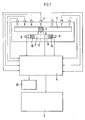
- the selector positions are detected by sensors 4, which give electrical signals to a control unit 5 of the transmission 3. From the selector position D, the selector lever 1 can be switched over a cross gate into a second shift gate 7 parallel to the first shift gate 2. The switching process is detected by a sensor 8, which delivers a signal to the control unit 5.
- a plus sensor 9 responds, the signal of which causes the control unit to shift up one gear on the transmission 3. Then the selector lever 1 is pressed back by a spring 10 into the neutral central position of the shift gate 7. When tapping again on sensor 9, there is a further upshift by one gear if the highest gear is not already engaged.
- a minus sensor 11 sends a signal to the control unit 5 and triggers a downshift by one gear on the transmission 3.
- An optical display device 12 is connected to the control unit 5, which displays the angular positions in the first shift gate 2 and the respectively engaged gear 1, 2, 3 or 4.
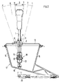
- the first shift gate 2 and the second shift gate 7, which run in the longitudinal direction of the motor vehicle, and the transverse gate 6 are used as backdrops for the Selector lever 1 formed in a cover plate 13.
- the cover plate 13 is screwed to a front side part 14 and a rear side part 15 and forms with them and a base plate 16 a hollow frame 17 which is fastened to the body of the motor vehicle.
- the part of the selector lever 1 protruding into the hollow frame 17 is connected to a universal joint 18, about the two transverse bearing pins 19 and 20 of which the selector lever 1 can be pivoted.
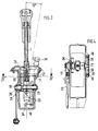
- the upper bearing pin 19 is mounted in the hollow frame 17.
- the selector lever for executing the selector positions P, R, N, D, 3, 2, 1 can be swiveled around it.
- a pivoting angle of a total of 34.6 ° is provided from the middle selector position D in the direction of travel of the motor vehicle, and a pivoting angle of 28.2 ° in the opposite direction.
- an actuating lever 21 fastened outside the hollow frame to the bearing pin 19 is carried, which engages in the transmission 3 via an actuating rod 22 articulated thereon, and the sensors 4 located there for the selected positions P, R, N, D, 3, 2, 1 pressed.
- an articulated frame 23 is connected to it, which is also pivoted when the selector positions are carried out.
- the bearing pin 20 is mounted in the articulated frame 13 below the bearing pin 19, about which the selector lever 1 can be pivoted when switching from the first shift gate 2 to the second shift gate 7.
- the swivel angle required for this is approx. 10 °.
- the switch positions of the selector lever are locked by a spring catch 24 acting on the underside of the selector lever 1 and fastened to the articulated frame 23.
- the spring cup is integrally formed on the outside of the hollow frame with it.
- a swiveling of the selector lever in the second shift gate 7 of approximately 5 is sufficient to make the plus sensor 9 or the minus sensor 11 respond in the opposite direction and to trigger an upshift or a downshift by one gear on the transmission 3.
- the plus sensor 9 and the minus sensor 11 and the sensor 8 which detects the changeover are designed as electromechanical microswitches and are accommodated in a switch housing 30 which is screwed onto the cover plate 13 at the top.
Landscapes
- Engineering & Computer Science (AREA)
- General Engineering & Computer Science (AREA)
- Mechanical Engineering (AREA)
- Chemical & Material Sciences (AREA)
- Combustion & Propulsion (AREA)
- Transportation (AREA)
- Arrangement Or Mounting Of Control Devices For Change-Speed Gearing (AREA)
- Control Of Transmission Device (AREA)
- Gear-Shifting Mechanisms (AREA)
Abstract
Description
Die Erfindung betrifft eine Schaltvorrichtung für ein Automatikgetriebe eines Kraftfahrzeugs nach dem Oberbegriff des Anspruchs 1.The invention relates to a switching device for an automatic transmission of a motor vehicle according to the preamble of
Ein derartiges Getriebe ist in Bosch Techn. Berichte 7 (1983)4, Seite 160 bis 166 beschrieben. Der Antrieb erfolgt über einen hydrodynamischen Wandler, der als Anfahrkupplung und zur Momentenübersetzung dient. Mittels einer Überbrückungskupplung kann der Wandler überbrückt und ein starrer Durchtrieb zu einem nachgeschalteten 4-Gang-Planetengetriebe hergestellt werden. Mit Sensoren werden die Getriebeausgangsdrehzahl, der Lastzustand des Motors, die Motordrehzahl sowie die Position des Wählhebels erfaßt und als elektrische Größen einem elektronischen Steuergerät zugeführt. Aus diesen Informationen wird nach einem vorgegebenen Rechenprogramm der jeweils optimale Gang bestimmt und vom Steuergerät über elektromagnetische Gangschaltventile am Getriebe hydraulisch geschaltet. An einem Programmschalter sind vom Fahrer drei Schaltprogramme wählbar: ein Economy-Programm für besonders wirtschaftliche Fahrweise, ein Leistungsprogramm für sportliches Fahren und ein Programm mit manueller Einstellung des jeweils gewünschten Getriebeganges über den Wählhebel. In einer Weiterentwicklung sind die ersten beiden Programme in das elektronische Steuergerät integriert, das zu diesem Zweck um Steuereinheiten erweitert wurde, die hier nicht näher erörtert werden sollen.Such a transmission is described in Bosch Technical Reports 7 (1983) 4, pages 160 to 166. The drive takes place via a hydrodynamic converter, which serves as a starting clutch and for torque transmission. The converter can be bridged by means of a lock-up clutch and a rigid through drive can be produced to a 4-speed planetary gear connected downstream. The transmission output speed, the load state of the engine, the engine speed and the position of the selector lever are detected by sensors and supplied to an electronic control unit as electrical variables. This information is used to determine the optimum gear in each case according to a predefined computer program and to be switched hydraulically by the control unit via electromagnetic gear shift valves on the transmission. The driver can select three gearshift programs at a program switch: an economy program for particularly economical driving, a performance program for sporty driving and a program with manual adjustment of the desired gearbox using the selector lever. In a further development, the first two programs are integrated in the electronic control unit, which has been expanded to include control units for this purpose, which will not be discussed here in greater detail.
Aus der Druckschrift "Electronically Controlled Mechanical Automatic Transmission for Heavy Duty Trucks and Buses", 31. Oktober 1986, SAE, Warrendale Pa, USA ist ein Automatikgetriebe mit einem in einer Schaltgasse bewegbaren Wählhebel bekannt. Durch Längsbewegen des Wählhebels sind die Fahrstufen R, N, D vorwählbar. Durch Querbewegen des Wahlhebels in der Schaltgasse sind die Vorwärtsgänge des Getriebes manuell schaltbar.From the publication "Electronically Controlled Mechanical Automatic Transmission for Heavy Duty Trucks and Buses", October 31, 1986, SAE, Warrendale Pa, USA, an automatic transmission with a selector lever movable in a shift gate is known. The driving stages R, N, D can be preselected by moving the selector lever lengthways. The forward gears of the transmission can be shifted manually by moving the selector lever in the shift gate.
Es ist die Aufgabe der Erfindung, eine Schaltvorrichtung für Automatikgetriebe zu schaffen, die bedienungsfreundlich gestaltet ist und dem Fahrer des Kraftfahrzeugs ein ergonomisches, Fehlbedienungen weitgehend ausschließendes Fahren ermöglicht.It is the object of the invention to provide a switching device for automatic transmissions which is designed to be user-friendly and which enables the driver of the motor vehicle to drive in an ergonomic manner which largely excludes incorrect operation.
Zur Lösung dieser Aufgabe dienen die kennzeichnenden Merkmale des Anspruchs 1. Wenn mit dem Wählhebel in einer ersten Schaltgasse die üblichen Wählstellungen eines Automatikgetreibes vorwählbar sind und nach Umschalten in eine zweite parallele Schaltgasse die Vorwärtsgänge des Getriebes mit einer Tippschaltung manuell schaltbar sind, hat der Fahrer die Möglichkeit, entweder im Automatikbetrieb oder Manuellbetrieb zu fahren. Zum Schalten der Gänge in der zweiten Schaltgasse genügt ein kurzes Antippen in der einen Richtung, um in einen Gang zu schalten. Danach kehrt der Wipphebel selbsttätig in die neutrale Mittellage zurück. Bei zweimaligem Antippen erfolgt eine Hoch- oder Rückschaltung um zwei Gänge. Bei dem gewählten Viergang-Getriebe kann durch dreimaliges Antippen maximal eine Hoch- oder Rückschaltung um drei Gänge erfolgen. Die Unteransprüche enthalten für diesen Zweck vorteilhafte konstruktive Ausgestaltungen des Wählhebels und seiner Lagerung in einem Hohlrahmen der Fahrzeugkarosserie.The characteristic features of
Ein Ausführungsbeispiel der Erfindung ist in der Zeichnung dargestellt und wird nachfolgend erläutert.An embodiment of the invention is shown in the drawing and is explained below.
Es zeigen:
- Fig. 1 Getriebe- Steuersystem mit Schaltvorrichtung,
- Fig. 2 Schaltvorrichtung im Längsschnitt,
- Fig. 3 Schaltvorrichtung im Querschnitt,
- Fig. 4 Schnitt nach der Linie IV-IV der Fig. 3.
- 1 transmission control system with switching device,
- 2 switching device in longitudinal section,
- 3 switching device in cross section,
- 4 section along the line IV-IV of FIG. 3rd
Mit einem Wählhebel 1, der in einer ersten Schaltgasse 2 in Längsrichtung des Kraftfahrzeugs verschwenkbar ist, sind die verschiedenen Stellungen P = Parken, R = Rückwärtsgang, N = Neutral-Null, D = Drive mit 4. Gang, 3 = 3. Gang, 2 = 2. Gang, 1 = 1. Gang eines automatischen Getriebes 3 anwählbar. Die Wählstellungen werden durch Sensoren 4 erfaßt, die elektrische Signale an ein Steuergerät 5 des Getriebes 3 geben. Aus der Wählstellung D heraus ist der Wählhebel 1 über eine Quergasse in eine zur ersten Schaltgasse 2 parallele zweite Schaltgasse 7 umschaltbar. Der Umschaltvorgang wird durch einen Sensor 8 erfaßt, der dabei ein Signal an das Steuergerät 5 liefert.The various positions P = parking, R = reverse gear, N = neutral-zero, D = drive with 4th gear, 3 = 3rd gear, with a
Beim Verschwenken des Wählhebels 1 in der zweiten Schaltgasse 7 in Fahrtrichtung des Kraftfahrzeugs spricht ein Plus-Sensor 9 an, dessen Signal das Steuergerät veranlaßt, am Getriebe 3 eine Hochschaltung um einen Gang vorzunehmen. Danach wird der Wählhebel 1 durch eine Feder 10 in die neutrale Mittellage der Schaltgasse 7 zurückgedrückt. Beim nochmaligen Antippen am Sensor 9 erfolgt eine weitere Hochschaltung um einen Gang, falls nicht bereits der höchste Getriebegang eingelegt ist. Beim Verschwenken des Wählhebels entgegen der Fahrtrichtung gibt ein Minus-Sensor 11 ein Signal an das Steuergerät 5 und löst am Getriebe 3 eine Rückschaltung um einen Gang aus. An das Steuergerät 5 ist ein optisches Anzeigegerät 12 angeschlossen, das die Winkelstellungen in der ersten Schaltgasse 2 und den jeweils eingelegten Getriebegang 1, 2, 3 oder 4 anzeigt.When the
Die konstruktive Ausführung der Schaltvorrichtung ist in Fig. 2, Fig. 3 und Fig. 4 dargestellt.The design of the switching device is shown in FIGS. 2, 3 and 4.
Die in Längsrichtung des Kraftfahrzeugs verlaufende erste Schaltgasse 2 und zweite Schaltgasse 7 sowie die Quergasse 6 sind als Kulissen für den Wählhebel 1 in einer Deckplatte 13 ausgebildet. Die Deckplatte 13 ist mit einem vorderen Seitenteil 14 und einem hinteren Seitenteil 15 verschraubt und bildet mit ihnen und einer Bodenplatte 16 einen Hohlrahmen 17, der an der Karosserie des Kraftfahrzeugs befestigt ist. Der in den Hohlrahmen 17 hineinragende Teil des Wählhebels 1 ist mit einem Kardangelenk 18 verbunden, um dessen zwei quer zueinanderliegende Lagerbolzen 19 und 20 der Wählhebel 1 schwenkbar ist.The
Der obere Lagerbolzen 19 ist in dem Hohlrahmen 17 gelagert. Um ihn ist der Wählhebel zur Ausführung der Wählstellungen P, R, N, D, 3, 2, 1 schwenkbar. Hierzu ist von der mittleren Wählstellung D aus in Fahrtrichtung des Kraftfahrzeugs ein Schwenkwinkel von insgesamt 34,6 ° , in Gegenrichtung ein Schwenkwinkel von 28,2° vorgesehen. Beim Verschwenken wird ein außerhalb des Hohlrahmens am Lagerbolzen 19 befestigter Betätigungshebel 21 mitgenommen, der über eine an ihm angelenkte Betätigungsstange 22 in das Getriebe 3 eingreift, und die dort befindlichen Sensoren 4 für die Wählstellungen P, R, N, D, 3, 2, 1 betätigt.The upper bearing
Am unteren Bereich des Wählhebels 1 ist mit ihm ein Gelenkrahmen 23 verbunden, der bei Ausführung der Wählstellungen mitverschwenkt wird. Im Gelenkrahmen 13 ist unterhalb des Lagerbolzens 19 der Lagerbolzen 20 gelagert, um den der Wählhebel 1 beim Umschalten von der ersten Schaltgasse 2 zur zweiten Schaltgasse 7 schwenkbar ist. Der hierzu erforderliche Schwenkwinkel beträgt ca. 10°. Durch eine an der Unterseite des Wählhebels 1 wirkende, am Gelenkrahmen 23 befestigte Federraste 24 werden die Umschaltstellungen des Wählhebels arretiert. Wird der Wählhebel 1 aus Stellung D heraus durch die Quergasse 6 hindurch in die zweite Schaltgasse 7 umgeschaltet, so wird die Verbindung zu dem auf dem Lagerbolzen 19 mit einer Vierkantverbindung 25 drehfesten Mitnahmestück 26 gelöst, um die in der zweiten Schaltgasse 7 auszuführenden Wippbegegungen nicht auf die im Getriebe 3 befindlichen Wählstellungs-Sensoren 4 zu übertragen.At the lower area of the
Nach Umschalten in die zweite Schaltgasse 7 greift ein an dem Wählhebel 1 senkrecht vorstehender Zapfen 27 zwischen zwei an ihm beidseitig anliegende Haltezapfen 28 ein, die durch die Feder 10 in einem Federtopf 29 abgestützt sind. Der Federtopf ist außen am Hohlrahmen mit ihm einstückig ausgebildet. Mit den Haltezapfen 28 und den Federn 10 wird der Wählhebel in der zweiten Schaltgasse 7 in neutraler Mittellage gehalten. Ein Verschwenken des Wählhebels in der zweiten Schaltgasse 7 von ca. 5 reicht aus, um den Plus-Sensor 9 bzw. in Gegenrichtung den Minus-Sensor 11 ansprechen zu lassen und am Getriebe 3 eine Hochschaltung oder eine Rückschaltung um einen Gang auszulösen. Der Plus-Sensor 9 und der Minus-Sensor 11 und der das Umschalten erfassende Sensor 8 sind als elektromechanische Mikroschalter ausgebildet und in einem Schaltergehäuse 30 untergebracht, das oben auf der Deckplatte 13 angeschraubt ist.After switching into the
Claims (8)
Applications Claiming Priority (2)
| Application Number | Priority Date | Filing Date | Title |
|---|---|---|---|
| DE3807881A DE3807881A1 (en) | 1988-03-10 | 1988-03-10 | SWITCHING DEVICE FOR AN AUTOMATIC TRANSMISSION OF A MOTOR VEHICLE |
| DE3807881 | 1988-03-10 |
Publications (4)
| Publication Number | Publication Date |
|---|---|
| EP0331797A2 EP0331797A2 (en) | 1989-09-13 |
| EP0331797A3 EP0331797A3 (en) | 1989-11-02 |
| EP0331797B1 true EP0331797B1 (en) | 1992-10-21 |
| EP0331797B2 EP0331797B2 (en) | 1996-01-17 |
Family
ID=6349331
Family Applications (1)
| Application Number | Title | Priority Date | Filing Date |
|---|---|---|---|
| EP88118936A Expired - Lifetime EP0331797B2 (en) | 1988-03-10 | 1988-11-14 | Gear-shifting device for an automatic transmission of a motor vehicle |
Country Status (5)
| Country | Link |
|---|---|
| US (1) | US4987792A (en) |
| EP (1) | EP0331797B2 (en) |
| JP (6) | JPH028545A (en) |
| DE (2) | DE3807881A1 (en) |
| HK (1) | HK91596A (en) |
Cited By (9)
| Publication number | Priority date | Publication date | Assignee | Title |
|---|---|---|---|---|
| US5197344A (en) * | 1990-02-22 | 1993-03-30 | Dr. Ing. H.C.F. Porsche Aktiengesellschaft | Shifting arrangement for an automatic transmission |
| EP0547598A1 (en) * | 1991-12-19 | 1993-06-23 | Mitsubishi Jukogyo Kabushiki Kaisha | Electronically controlled automatic transmission for vehicles |
| EP0575658A1 (en) * | 1992-06-30 | 1993-12-29 | Aisin Aw Co., Ltd. | Shift system having a manual speed selecting mechanism for a vehicular automatic transmission |
| FR2694525A1 (en) * | 1992-08-06 | 1994-02-11 | Peugeot | Automatic gearbox control device. |
| EP0685664A2 (en) | 1994-06-01 | 1995-12-06 | ZF FRIEDRICHSHAFEN Aktiengesellschaft | Shift control mechanism for an automatic transmission |
| EP0736408A2 (en) * | 1995-04-08 | 1996-10-09 | Ford-Werke Aktiengesellschaft | Control lever for automatic gearboxes of motor vehicles with alternative manual gear selection |
| EP0798146A2 (en) * | 1996-03-29 | 1997-10-01 | Dr.Ing.h.c. F. Porsche Aktiengesellschaft | Guide for a selector lever |
| US5845535A (en) * | 1996-01-11 | 1998-12-08 | Mitsubishi Jidosha Kogyo Kabushiki Kaisha | Gearshift apparatus for a vehicle |
| US5899115A (en) * | 1995-10-24 | 1999-05-04 | Fuji Kiko Co., Ltd. | Shift select lever device for automatic transmission |
Families Citing this family (113)
| Publication number | Priority date | Publication date | Assignee | Title |
|---|---|---|---|---|
| DE3927250A1 (en) * | 1989-08-18 | 1991-02-21 | Porsche Ag | SWITCHING DEVICE |
| US5070740A (en) * | 1988-03-10 | 1991-12-10 | Dr. Ing. H.C.F. Porsche Ag | Shifting arrangement for an automatic transmission of a motor vehicle |
| DE3927922C2 (en) * | 1988-03-10 | 1995-06-14 | Porsche Ag | Switching device for a motor vehicle transmission |
| US5044220A (en) * | 1988-03-10 | 1991-09-03 | Dr. Ing. H.C.F. Porsche Ag | Shifting arrangement for an automatic transmission of a motor vehicle |
| DE3927248C1 (en) * | 1989-08-18 | 1991-02-07 | Dr.Ing.H.C. F. Porsche Ag, 7000 Stuttgart, De | |
| DE3881524D1 (en) * | 1988-09-29 | 1993-07-08 | Porsche Ag | SWITCHING DEVICE FOR AN AUTOMATIC TRANSMISSION OF A MOTOR VEHICLE. |
| DE3832971A1 (en) * | 1988-09-29 | 1990-04-12 | Porsche Ag | DISPLAY DEVICE FOR AN AUTOMATIC MOTOR VEHICLE TRANSMISSION |
| DE3925064A1 (en) * | 1989-07-28 | 1991-01-31 | Bayerische Motoren Werke Ag | Selector lever for motor vehicle gearbox - engages individual gear electronic gear control and is moved in two operating planes at right angles |
| DE3927249A1 (en) * | 1989-08-18 | 1991-02-21 | Porsche Ag | Vehicular automatic gear-change with electronic control unit - has leaf-spring latching device for holding gear selector lever in either of two parallel paths |
| DE59001427D1 (en) * | 1989-08-24 | 1993-06-17 | Porsche Ag | SWITCHING DEVICE FOR A MOTOR VEHICLE TRANSMISSION. |
| DE3929268A1 (en) * | 1989-09-02 | 1991-03-07 | Bayerische Motoren Werke Ag | MOTOR VEHICLE TRANSMISSION |
| JPH03153957A (en) * | 1989-11-09 | 1991-07-01 | Aisin Aw Co Ltd | Manual select of automatic transmission for vehicle |
| US5178042A (en) * | 1989-11-09 | 1993-01-12 | Aisin Aw Co., Ltd. | Manual speed selector of automatic vehicle transmission |
| JPH03153958A (en) * | 1989-11-09 | 1991-07-01 | Aisin Aw Co Ltd | Manual select device of automatic transmission for vehicle |
| DE4003899C1 (en) * | 1990-02-09 | 1991-05-23 | Mercedes-Benz Aktiengesellschaft, 7000 Stuttgart, De | |
| JP2748642B2 (en) * | 1990-03-12 | 1998-05-13 | トヨタ自動車株式会社 | Control device for automatic transmission |
| DE4016977A1 (en) * | 1990-05-25 | 1991-11-28 | Meflex Telecontrol Gmbh & Co | TRANSMITTER DEVICE IN A HOUSING FOR THE MOVEMENT OF TAX TRAIN, RODS AND THE LIKE. |
| DE4029330A1 (en) * | 1990-09-15 | 1992-03-26 | Porsche Ag | SWITCHING DEVICE FOR A MOTOR VEHICLE TRANSMISSION |
| JP3092234B2 (en) * | 1991-08-16 | 2000-09-25 | アイシン・エィ・ダブリュ株式会社 | Hydraulic control device for automatic transmission for vehicles |
| JP3280412B2 (en) * | 1992-04-24 | 2002-05-13 | アイシン・エィ・ダブリュ株式会社 | Automatic transmission |
| EP0567157B1 (en) * | 1992-04-24 | 1996-07-03 | Toyota Jidosha Kabushiki Kaisha | Shift control system for manually shiftable automatic transmission |
| DE4217773A1 (en) * | 1992-05-29 | 1993-12-02 | Audi Ag | Vehicle automatic gearbox selector - has conventional arrangement of manual gears and electronic control unit for gear changing in DRIVE position |
| US5415056A (en) * | 1992-09-21 | 1995-05-16 | Toyota Jidosha Kabushiki Kaisha | Shift control system for manually shiftable automatic transmission |
| GB9322836D0 (en) * | 1993-11-05 | 1993-12-22 | Rover Group | A selector mechanism for a vehicle transmission |
| US5406860A (en) * | 1993-12-01 | 1995-04-18 | Deere & Company | Transmission shift lever assembly |
| US5437204A (en) * | 1993-12-20 | 1995-08-01 | Ford Motor Company | System for selecting the operating ranges of an automatic transmission |
| US5433124A (en) * | 1993-12-20 | 1995-07-18 | Ford Motor Company | Electronic range selection in an automatic transmission |
| US5509322A (en) * | 1994-06-02 | 1996-04-23 | Chrysler Corporation | Shift control mechanism to manually shift an automatic transmission |
| US5722292A (en) * | 1994-06-02 | 1998-03-03 | Chrysler Corporation | Shift control mechanism to manually shift an automatic transmission |
| US5492509A (en) * | 1994-06-06 | 1996-02-20 | Ford Motor Company | Operating range selection of an automatic transmission |
| US5492523A (en) * | 1994-06-06 | 1996-02-20 | Ford Motor Company | Operating range selection of an automatic transmission |
| US5762580A (en) * | 1994-06-06 | 1998-06-09 | Ford Global Technologies, Inc. | Operating range selection of an automatic transmission |
| DE4426207C5 (en) * | 1994-07-23 | 2008-08-28 | Bayerische Motoren Werke Aktiengesellschaft | Selection device for an automatic transmission of a motor vehicle |
| DE4433595A1 (en) * | 1994-09-21 | 1996-03-28 | Teves Gmbh Alfred | Steering column switch as gear switch with fixable neutral position |
| JP3104160B2 (en) * | 1995-02-01 | 2000-10-30 | 本田技研工業株式会社 | Control device for automatic transmission for vehicles |
| JP3231205B2 (en) * | 1995-02-01 | 2001-11-19 | 本田技研工業株式会社 | Control device for automatic transmission for vehicles |
| JP3176522B2 (en) * | 1995-02-06 | 2001-06-18 | 本田技研工業株式会社 | Control device for automatic transmission for vehicles |
| ES2115493B1 (en) * | 1995-02-20 | 1999-02-16 | Fico Triad Sa | CONTROL DEVICE FOR AUTOMATIC / MANUAL-ELECTRONIC MIXED SPEED CHANGE. |
| JP3035184B2 (en) * | 1995-03-02 | 2000-04-17 | 本田技研工業株式会社 | Control device for hydraulically operated transmission |
| DE69615757T2 (en) * | 1995-06-21 | 2002-04-18 | Aisin Aw Co | Switching device for an automatic motor vehicle transmission |
| US5767769A (en) * | 1995-07-28 | 1998-06-16 | Chrysler Corporation | Method of displaying a shift lever position for an electronically-controlled automatic transmission |
| US5680307A (en) * | 1995-06-28 | 1997-10-21 | Chrysler Corporation | Method of shifting in a manual mode of an electronically-controlled automatic transmission system |
| DE19526059C2 (en) * | 1995-07-17 | 1999-05-27 | Lemfoerder Metallwaren Ag | Switching device for an automatic transmission of a motor vehicle |
| US5675315A (en) * | 1995-07-28 | 1997-10-07 | Chrysler Corporation | Electronic gear display for an electronically-controlled automatic transmission system |
| US5584209A (en) * | 1995-07-28 | 1996-12-17 | Chrysler Corporation | Electric circuit for manual shifting of an electronically-controlled automatic transmission system |
| CN1075612C (en) * | 1996-01-11 | 2001-11-28 | 三菱自动车工业株式会社 | Gearshift apparatus for vehicle |
| EP0794362B1 (en) * | 1996-03-08 | 2001-09-19 | ZF Lemförder Metallwaren AG | Gear selector for a transmission |
| DE19612856A1 (en) * | 1996-03-30 | 1997-10-02 | Bayerische Motoren Werke Ag | Switching device |
| US5791197A (en) * | 1996-07-24 | 1998-08-11 | Grand Haven Stamped Products | Automatic transmission shifter with manual shift mode |
| DE19633948A1 (en) * | 1996-08-22 | 1998-02-26 | Bayerische Motoren Werke Ag | Selector device for an automatic transmission of a motor vehicle |
| JP3447482B2 (en) * | 1996-08-29 | 2003-09-16 | ナイルス株式会社 | Speed change device for vehicle |
| JP3216542B2 (en) * | 1996-09-02 | 2001-10-09 | トヨタ自動車株式会社 | Shift range control device for automatic transmission |
| JP3600382B2 (en) * | 1996-09-19 | 2004-12-15 | ジヤトコ株式会社 | Transmission control device for automatic transmission |
| JP3638389B2 (en) * | 1996-11-05 | 2005-04-13 | 本田技研工業株式会社 | Control device for automatic transmission for vehicle |
| JPH10141494A (en) * | 1996-11-05 | 1998-05-29 | Honda Motor Co Ltd | Control device for vehicular automatic transmission |
| DE19754247B4 (en) * | 1996-12-13 | 2009-08-06 | Volkswagen Ag | Actuator of gear ratios of an automatic transmission |
| KR19980060490A (en) * | 1996-12-31 | 1998-10-07 | 박병재 | Shift lever structure of automatic transmission for manual mode |
| US5799539A (en) * | 1997-01-21 | 1998-09-01 | Ford Global Technologies, Inc. | Manually shifted automatic transmission lever |
| US5845534A (en) * | 1997-05-15 | 1998-12-08 | Hyundai Motor Company | Selector level assembly for an automatic transmission of a vehicle |
| FR2764025B1 (en) * | 1997-05-30 | 1999-07-16 | Peugeot | DEVICE FOR CONTROLLING AN AUTOMATIC GEARBOX WITH STAGE REPORTS |
| JP3185720B2 (en) * | 1997-07-29 | 2001-07-11 | 日産自動車株式会社 | Control circuit for automatic transmission with manual shift function |
| EP0895003B1 (en) * | 1997-07-29 | 2004-10-06 | Nissan Motor Company Limited | Shifting device for an automatic transmission |
| SE510069C2 (en) | 1997-08-19 | 1999-04-12 | Scandmec Ab | Control device and the use of the control device in a motor vehicle |
| KR19990072573A (en) * | 1998-02-16 | 1999-09-27 | 그라우엘 안드레아스 | Transmission for use in power trains of motor vehicles |
| DE19915892B4 (en) * | 1998-04-09 | 2008-11-06 | Nissan Motor Co., Ltd., Yokohama | Switching device for an automatic transmission |
| US6295886B1 (en) | 1998-10-08 | 2001-10-02 | Dura Global Technologies | Vehicle shift mechanism for an automatic transmission |
| DE19902639A1 (en) * | 1999-01-23 | 2000-07-27 | Bayerische Motoren Werke Ag | Switching system |
| FR2789949B1 (en) | 1999-02-19 | 2001-04-20 | Renault | PULSE CONTROL DEVICE FOR GEARBOX |
| FR2791010B1 (en) * | 1999-03-15 | 2001-04-20 | United Parts France Sa | PULSE SPEED CHANGE CONTROL DEVICE |
| DE19951374B4 (en) | 1999-10-26 | 2007-10-31 | ZF Lemförder Metallwaren AG | Switching device for a controlled by an electronic control unit vehicle automatic transmission |
| US6230579B1 (en) | 1999-11-17 | 2001-05-15 | Teleflex Incorporated | Multi-mode shifter assembly joint |
| JP2001158250A (en) * | 1999-12-01 | 2001-06-12 | Sakae Riken Kogyo Kk | Shift device for transmission |
| US6382046B1 (en) | 2000-02-09 | 2002-05-07 | Dura Automotive Properties | Transmission shifter with cable disengagement mechanism |
| JP4546601B2 (en) | 2000-02-21 | 2010-09-15 | 本田技研工業株式会社 | Shift control device for automatic transmission for vehicle |
| JP2001248716A (en) | 2000-03-07 | 2001-09-14 | Honda Motor Co Ltd | Shift control device for vehicular automatic transmission |
| DE10015079C2 (en) * | 2000-03-28 | 2002-01-24 | Zf Lemfoerder Metallwaren Ag | Switching device for an automatic transmission of a motor vehicle |
| DE60238731D1 (en) * | 2001-03-02 | 2011-02-10 | Toyota Motor Co Ltd | Switching device for a motor vehicle |
| DE10125700A1 (en) * | 2001-05-25 | 2002-11-28 | Zahnradfabrik Friedrichshafen | Shift arrangement for vehicle automatic gearbox, especially for motor vehicle, generates shift signal depending on combination of successive pulses of manual command |
| KR100460716B1 (en) * | 2002-01-02 | 2004-12-08 | 삼립산업 주식회사 | tip tronics type shift lever device for an automobile |
| EP1333199B1 (en) * | 2002-01-31 | 2007-01-24 | Schaeffler KG | Device for increasing a selection force |
| AU2002951613A0 (en) * | 2002-09-24 | 2002-10-10 | M.T.M. Pty Ltd | A shift lever assembly |
| DE10249074B4 (en) | 2002-10-21 | 2006-05-04 | ZF Lemförder Metallwaren AG | Switching device for an automatic transmission |
| KR100494788B1 (en) * | 2002-10-24 | 2005-06-13 | 현대자동차주식회사 | shift lock device for a shift lever of an auto transmission |
| DE10252009B4 (en) * | 2002-11-06 | 2005-03-31 | ZF Lemförder Metallwaren AG | Switching device for transmitting switching commands to an automatic transmission |
| USPP15990P3 (en) * | 2003-04-23 | 2005-09-20 | J. C. Bakker & Sons Limited | Lilac plant named ‘Golden Eclipse’ |
| JP4506097B2 (en) * | 2003-04-25 | 2010-07-21 | いすゞ自動車株式会社 | Vehicle parking device |
| US7393304B2 (en) | 2003-05-15 | 2008-07-01 | Grand Haven Stamped Products | Shifter with gear position indicator |
| US7221248B2 (en) * | 2003-05-15 | 2007-05-22 | Grand Haven Stamped Products | Solenoid with noise reduction |
| JP4360126B2 (en) * | 2003-05-28 | 2009-11-11 | いすゞ自動車株式会社 | Vehicle parking device |
| JP2005231587A (en) * | 2004-02-23 | 2005-09-02 | Honda Motor Co Ltd | Operating device for automatic transmission |
| DE102004024954A1 (en) * | 2004-05-21 | 2005-12-08 | Robert Bosch Gmbh | Sensor for a transmission control in particular of a motor vehicle |
| US7568404B2 (en) | 2004-07-26 | 2009-08-04 | Ghsp, A Division Of Jsj Corporation | Shifter having neutral lock |
| US7328782B2 (en) * | 2004-07-26 | 2008-02-12 | Grand Haven Stamped Products Company, A Division Of Jsj Corporation | Vehicle shifter with powered pawl having neutral lock |
| US8893571B2 (en) * | 2007-08-17 | 2014-11-25 | Steering Solutions Ip Holding Corporation | Transmission shift assembly for a vehicle and a method of monitoring the same |
| US9043100B2 (en) | 2007-08-17 | 2015-05-26 | Steering Solutions Ip Holding Corporation | Transmission shift assembly for a vehicle and a method of monitoring the same |
| JP2009156435A (en) | 2007-12-27 | 2009-07-16 | Aisin Aw Co Ltd | Control apparatus for automatic transmission |
| JP2009156433A (en) * | 2007-12-27 | 2009-07-16 | Aisin Aw Co Ltd | Control apparatus for automatic transmission |
| JP2009156434A (en) * | 2007-12-27 | 2009-07-16 | Aisin Aw Co Ltd | Control apparatus for automatic transmission |
| JP2009156436A (en) * | 2007-12-27 | 2009-07-16 | Aisin Aw Co Ltd | Control apparatus for automatic transmission |
| JP5040784B2 (en) * | 2008-04-16 | 2012-10-03 | 日産自動車株式会社 | Shifting operation device |
| KR100955915B1 (en) | 2008-04-21 | 2010-05-03 | 에스엘 주식회사 | Apparatus for electron control transmission |
| JP4593654B2 (en) * | 2008-06-10 | 2010-12-08 | ジヤトコ株式会社 | Stepped automatic transmission |
| DE102008042959A1 (en) | 2008-10-20 | 2010-04-22 | Zf Friedrichshafen Ag | Method for controlling a motor vehicle drive train |
| KR101459799B1 (en) * | 2009-12-04 | 2014-11-07 | 현대자동차주식회사 | Electronic Shifting Apparatus for Vehicle |
| DE102011079849A1 (en) | 2011-07-26 | 2013-01-31 | Zf Friedrichshafen Ag | Switching device for automatic multi-speed motor vehicle transmission, triggers first gear shift in transmission if driver sets first gear shift to one selector, while other gear shift triggers if two gear shifts are in same selector |
| KR101316157B1 (en) * | 2011-09-06 | 2013-10-08 | 기아자동차주식회사 | Device of providing shift feeling for shift lever in automatic transmission |
| US9676079B2 (en) | 2013-03-11 | 2017-06-13 | Stanley Black & Decker, Inc. | Clamp |
| CN108533729B (en) * | 2018-03-28 | 2024-04-12 | 宝鸡法士特齿轮有限责任公司 | Transmission operating device |
| US10525817B2 (en) | 2018-05-21 | 2020-01-07 | Earl E. Irwin | Supplemental transmission assembly |
| KR102599389B1 (en) | 2018-06-29 | 2023-11-09 | 현대자동차주식회사 | Method for sending shift signal of electronic shift system |
| JP2020032927A (en) * | 2018-08-31 | 2020-03-05 | 富士機工株式会社 | Shift lever device |
| JP7276119B2 (en) * | 2019-12-25 | 2023-05-18 | マツダ株式会社 | Vehicle shift device |
| JP2022060945A (en) | 2020-10-05 | 2022-04-15 | 株式会社クボタ | Multiple-purpose vehicle |
Family Cites Families (21)
| Publication number | Priority date | Publication date | Assignee | Title |
|---|---|---|---|---|
| US3640157A (en) * | 1968-11-27 | 1972-02-08 | Gen Motors Corp | Power train control system |
| SE366502B (en) * | 1968-12-31 | 1974-04-29 | Citroen Sa | |
| US3650161A (en) * | 1969-10-18 | 1972-03-21 | Toyota Motor Co Ltd | Automatic shift control system for automatic transmission |
| HU174407B (en) * | 1975-01-23 | 1979-12-28 | Zahnradfabrik Friedrichshafen | Starting switch for electrohydraulic drives |
| JPS6145541Y2 (en) * | 1981-05-20 | 1986-12-22 | ||
| US4442730A (en) * | 1981-08-31 | 1984-04-17 | Twin Disc, Incorporated | Vehicle transmission system and a single lever control device therefor |
| DE3138827A1 (en) * | 1981-09-30 | 1983-04-14 | Wabco Westinghouse Fahrzeugbremsen GmbH, 3000 Hannover | GEAR SELECTOR FOR A GEARBOX |
| DE3277066D1 (en) * | 1982-04-19 | 1987-10-01 | Caterpillar Inc | A mounting apparatus for a control lever |
| JPS5965653A (en) * | 1982-10-07 | 1984-04-13 | Isuzu Motors Ltd | Operating method of speed change gears |
| DE3237509A1 (en) * | 1982-10-09 | 1984-04-12 | Wabco Westinghouse Fahrzeugbremsen GmbH, 3000 Hannover | GEAR SHIFT FOR A FOREIGN ACTUATED GEARBOX |
| DE3238219A1 (en) * | 1982-10-15 | 1984-04-19 | Wabco Westinghouse Fahrzeugbremsen GmbH, 3000 Hannover | AUXILIARY ACTUATOR GEARBOX |
| GB8307095D0 (en) * | 1983-03-15 | 1983-04-20 | Massey Ferguson Perkins Ltd | Gear selector means |
| DE3314111A1 (en) * | 1983-04-19 | 1984-10-25 | Dr.Ing.H.C. F. Porsche Ag, 7000 Stuttgart | DEVICE FOR INDIVIDUAL POSITION INDICATION OF HYDRAULICALLY ACTUATED SHIFT RODS |
| US4646582A (en) * | 1983-06-27 | 1987-03-03 | Mitsubishi Jidosha Kogyo Kabushiki Kaisha | Operating device for transmission |
| EP0180583B1 (en) * | 1983-08-12 | 1988-01-20 | ZF FRIEDRICHSHAFEN Aktiengesellschaft | Pressure-actuated gear shifting device |
| DE3434205A1 (en) * | 1984-09-18 | 1986-03-27 | Wabco Westinghouse Fahrzeugbremsen GmbH, 3000 Hannover | SENSOR FOR A MANUAL TRANSMISSION OF A MOTOR VEHICLE |
| JPS61157855A (en) * | 1984-12-27 | 1986-07-17 | Nissan Motor Co Ltd | Manual speed change gear for automatic transmission |
| DE3523381A1 (en) * | 1985-06-29 | 1987-01-08 | Porsche Ag | SINGLE LEVER CONTROL FOR A MANUAL GEAR CHAIN VEHICLE |
| JPS6234214A (en) * | 1985-08-07 | 1987-02-14 | Hino Motors Ltd | Gear change lever unit |
| WO1987000806A1 (en) * | 1985-08-10 | 1987-02-12 | Zahnradfabrik Friedrichshafen Ag | Control system for automatic gear-changing on multiple-speed gearboxes |
| DE3717675C5 (en) * | 1987-05-26 | 2005-12-15 | Bayerische Motoren Werke Ag | Switching device for a motor vehicle with automatic transmission |
-
1988
- 1988-03-10 DE DE3807881A patent/DE3807881A1/en active Granted
- 1988-11-14 EP EP88118936A patent/EP0331797B2/en not_active Expired - Lifetime
- 1988-11-14 DE DE8888118936T patent/DE3875475D1/en not_active Expired - Lifetime
-
1989
- 1989-01-27 US US07/302,387 patent/US4987792A/en not_active Expired - Lifetime
- 1989-03-09 JP JP1055245A patent/JPH028545A/en active Pending
-
1996
- 1996-05-23 HK HK91596A patent/HK91596A/en not_active IP Right Cessation
-
1997
- 1997-02-13 JP JP9028866A patent/JP3027722B2/en not_active Expired - Fee Related
-
1998
- 1998-04-02 JP JP10089990A patent/JP3027738B2/en not_active Expired - Fee Related
- 1998-04-02 JP JP10089991A patent/JP3029599B2/en not_active Expired - Fee Related
- 1998-04-02 JP JP10089986A patent/JP3037656B2/en not_active Expired - Fee Related
- 1998-04-02 JP JP10089989A patent/JP3032501B2/en not_active Expired - Lifetime
Cited By (14)
| Publication number | Priority date | Publication date | Assignee | Title |
|---|---|---|---|---|
| US5197344A (en) * | 1990-02-22 | 1993-03-30 | Dr. Ing. H.C.F. Porsche Aktiengesellschaft | Shifting arrangement for an automatic transmission |
| EP0547598A1 (en) * | 1991-12-19 | 1993-06-23 | Mitsubishi Jukogyo Kabushiki Kaisha | Electronically controlled automatic transmission for vehicles |
| US5351570A (en) * | 1991-12-19 | 1994-10-04 | Mitsubishi Jukogyo Kabushiki Kaisha | Electronically controlled automatic transmission for vehicles |
| EP0575658A1 (en) * | 1992-06-30 | 1993-12-29 | Aisin Aw Co., Ltd. | Shift system having a manual speed selecting mechanism for a vehicular automatic transmission |
| FR2694525A1 (en) * | 1992-08-06 | 1994-02-11 | Peugeot | Automatic gearbox control device. |
| EP0685664A2 (en) | 1994-06-01 | 1995-12-06 | ZF FRIEDRICHSHAFEN Aktiengesellschaft | Shift control mechanism for an automatic transmission |
| EP0736408A2 (en) * | 1995-04-08 | 1996-10-09 | Ford-Werke Aktiengesellschaft | Control lever for automatic gearboxes of motor vehicles with alternative manual gear selection |
| EP0736408A3 (en) * | 1995-04-08 | 1997-08-20 | Ford Werke Ag | Control lever for automatic gearboxes of motor vehicles with alternative manual gear selection |
| US5682789A (en) * | 1995-04-08 | 1997-11-04 | Ford Global Technologies, Inc. | Selector lever system for manually shiftable automatic transmissions |
| US5899115A (en) * | 1995-10-24 | 1999-05-04 | Fuji Kiko Co., Ltd. | Shift select lever device for automatic transmission |
| EP1018612A2 (en) * | 1995-10-24 | 2000-07-12 | Fuji Kiko Co., Ltd. | Shift lever device for an automatic transmission |
| US5845535A (en) * | 1996-01-11 | 1998-12-08 | Mitsubishi Jidosha Kogyo Kabushiki Kaisha | Gearshift apparatus for a vehicle |
| EP0798146A2 (en) * | 1996-03-29 | 1997-10-01 | Dr.Ing.h.c. F. Porsche Aktiengesellschaft | Guide for a selector lever |
| US5875684A (en) * | 1996-03-29 | 1999-03-02 | Dr. Ing. H.C.F. Porsche Ag | Guide for a selector lever |
Also Published As
| Publication number | Publication date |
|---|---|
| JP3027722B2 (en) | 2000-04-04 |
| JP3027738B2 (en) | 2000-04-04 |
| JPH10324169A (en) | 1998-12-08 |
| EP0331797A2 (en) | 1989-09-13 |
| US4987792A (en) | 1991-01-29 |
| DE3875475D1 (en) | 1992-11-26 |
| JPH028545A (en) | 1990-01-12 |
| DE3807881C2 (en) | 1992-08-27 |
| JP3037656B2 (en) | 2000-04-24 |
| EP0331797A3 (en) | 1989-11-02 |
| JPH10329565A (en) | 1998-12-15 |
| JPH10329566A (en) | 1998-12-15 |
| EP0331797B2 (en) | 1996-01-17 |
| HK91596A (en) | 1996-05-31 |
| JP3032501B2 (en) | 2000-04-17 |
| JPH10338048A (en) | 1998-12-22 |
| JP3029599B2 (en) | 2000-04-04 |
| DE3807881A1 (en) | 1989-09-21 |
| JPH09309355A (en) | 1997-12-02 |
Similar Documents
| Publication | Publication Date | Title |
|---|---|---|
| EP0331797B1 (en) | Gear-shifting device for an automatic transmission of a motor vehicle | |
| DE3927922C2 (en) | Switching device for a motor vehicle transmission | |
| DE4005588C2 (en) | Switching device for an automatic transmission | |
| EP1141587B1 (en) | Gear-change system for an electronically controlled vehicle automatic gearbox | |
| EP0476291B1 (en) | Selector device for a change speed gearing of an automotive vehicle | |
| EP0568571B1 (en) | Gear and gear-range selector for a semi-automatic or fully automatic vehicle gearbox | |
| EP0108209A2 (en) | Gear shifting for a power assisted transmission | |
| DE102007010052A1 (en) | Control device for an automatic transmission | |
| EP0107761A2 (en) | Speed shifting for a power assisted transmission | |
| EP1338831A2 (en) | Transmission gear shifting device | |
| DE3832970C2 (en) | Display device for an automatic motor vehicle transmission | |
| DE4311886A1 (en) | Device and method for controlling an automatic transmission | |
| DE102008048902B4 (en) | Gear shift control system for an automatic transmission | |
| DE10157393B4 (en) | Method and device for controlling the circuits of an automatic transmission of a motor vehicle | |
| DE102011056356A1 (en) | INTEGRATED CONTROL ROCKER DEVICE | |
| DE4006653A1 (en) | Gearshift control with automatic control of clutch | |
| DE4233938A1 (en) | Selector switch unit for electronic control of automatic gearbox - has steering column selector lever able to move in two planes at right angles giving normal, automatic or restricted operating modes | |
| DE2343711C2 (en) | Switching device for a mechanical change gearbox in motor vehicles | |
| DE3337930C2 (en) | Selector switch in a shift control for automatic transmissions | |
| DE19754250B4 (en) | Actuating device for selecting driving steps and for manual shifting of gear ratios of an automatic transmission | |
| EP0413932B1 (en) | Gear change device for a vehicle transmission | |
| DE60006457T2 (en) | Compact gearbox with swivel feet for operating shift forks | |
| DE60102992T2 (en) | vehicle transmissions | |
| DE19632736C2 (en) | Switching device for the automatic transmission of a motor vehicle | |
| EP0997668A2 (en) | Ratio selection device for vehicle |
Legal Events
| Date | Code | Title | Description |
|---|---|---|---|
| PUAI | Public reference made under article 153(3) epc to a published international application that has entered the european phase |
Free format text: ORIGINAL CODE: 0009012 |
|
| AK | Designated contracting states |
Kind code of ref document: A2 Designated state(s): DE FR GB IT SE |
|
| PUAL | Search report despatched |
Free format text: ORIGINAL CODE: 0009013 |
|
| AK | Designated contracting states |
Kind code of ref document: A3 Designated state(s): DE FR GB IT SE |
|
| 17P | Request for examination filed |
Effective date: 19900309 |
|
| 17Q | First examination report despatched |
Effective date: 19910820 |
|
| ITF | It: translation for a ep patent filed |
Owner name: DE DOMINICIS & MAYER S.R.L. |
|
| GRAA | (expected) grant |
Free format text: ORIGINAL CODE: 0009210 |
|
| AK | Designated contracting states |
Kind code of ref document: B1 Designated state(s): DE FR GB IT SE |
|
| REF | Corresponds to: |
Ref document number: 3875475 Country of ref document: DE Date of ref document: 19921126 |
|
| GBT | Gb: translation of ep patent filed (gb section 77(6)(a)/1977) | ||
| ET | Fr: translation filed | ||
| PLBI | Opposition filed |
Free format text: ORIGINAL CODE: 0009260 |
|
| 26 | Opposition filed |
Opponent name: KOBAYASHI, TETSUO Effective date: 19930714 |
|
| EAL | Se: european patent in force in sweden |
Ref document number: 88118936.9 |
|
| PUAH | Patent maintained in amended form |
Free format text: ORIGINAL CODE: 0009272 |
|
| STAA | Information on the status of an ep patent application or granted ep patent |
Free format text: STATUS: PATENT MAINTAINED AS AMENDED |
|
| 27A | Patent maintained in amended form |
Effective date: 19960117 |
|
| AK | Designated contracting states |
Kind code of ref document: B2 Designated state(s): DE FR GB IT SE |
|
| GBTA | Gb: translation of amended ep patent filed (gb section 77(6)(b)/1977) |
Effective date: 19960228 |
|
| ET3 | Fr: translation filed ** decision concerning opposition | ||
| ITF | It: translation for a ep patent filed |
Owner name: DE DOMINICIS & MAYER S.R.L. |
|
| APAC | Appeal dossier modified |
Free format text: ORIGINAL CODE: EPIDOS NOAPO |
|
| APAC | Appeal dossier modified |
Free format text: ORIGINAL CODE: EPIDOS NOAPO |
|
| REG | Reference to a national code |
Ref country code: GB Ref legal event code: IF02 |
|
| APAH | Appeal reference modified |
Free format text: ORIGINAL CODE: EPIDOSCREFNO |
|
| PGFP | Annual fee paid to national office [announced via postgrant information from national office to epo] |
Ref country code: DE Payment date: 20071018 Year of fee payment: 20 |
|
| PGFP | Annual fee paid to national office [announced via postgrant information from national office to epo] |
Ref country code: IT Payment date: 20071126 Year of fee payment: 20 |
|
| PGFP | Annual fee paid to national office [announced via postgrant information from national office to epo] |
Ref country code: SE Payment date: 20071114 Year of fee payment: 20 |
|
| PGFP | Annual fee paid to national office [announced via postgrant information from national office to epo] |
Ref country code: GB Payment date: 20071120 Year of fee payment: 20 Ref country code: FR Payment date: 20071122 Year of fee payment: 20 |
|
| REG | Reference to a national code |
Ref country code: GB Ref legal event code: PE20 Expiry date: 20081113 |
|
| PG25 | Lapsed in a contracting state [announced via postgrant information from national office to epo] |
Ref country code: GB Free format text: LAPSE BECAUSE OF EXPIRATION OF PROTECTION Effective date: 20081113 |
|
| REG | Reference to a national code |
Ref country code: FR Ref legal event code: TP |
|
| REG | Reference to a national code |
Ref country code: FR Ref legal event code: CD |