EP0683442B1 - Elektronische Kleinuhr - Google Patents
Elektronische Kleinuhr Download PDFInfo
- Publication number
- EP0683442B1 EP0683442B1 EP19950810316 EP95810316A EP0683442B1 EP 0683442 B1 EP0683442 B1 EP 0683442B1 EP 19950810316 EP19950810316 EP 19950810316 EP 95810316 A EP95810316 A EP 95810316A EP 0683442 B1 EP0683442 B1 EP 0683442B1
- Authority
- EP
- European Patent Office
- Prior art keywords
- casing
- watch
- module
- generator
- power source
- Prior art date
- Legal status (The legal status is an assumption and is not a legal conclusion. Google has not performed a legal analysis and makes no representation as to the accuracy of the status listed.)
- Expired - Lifetime
Links
Images


Classifications
-
- G—PHYSICS
- G04—HOROLOGY
- G04C—ELECTROMECHANICAL CLOCKS OR WATCHES
- G04C10/00—Arrangements of electric power supplies in time pieces
Definitions
- the invention relates to an electronic Watch with one arranged in a housing Clockwork, with a rechargeable that feeds the clockwork Power source and a charging this power source Generator, the rotor of a flywheel is drivable.
- Such a small watch in the form of a wristwatch is known from DE-A-2751 797 and has as Power source a small accumulator and one Generator, whose moving part with a through the movement of the clock actuatable inertial rotor as Flywheel is coupled.
- This flywheel is in a central point of a board, which is also the Power source carries, stored and at its edge provided with a permanent magnet.
- This Permanent magnet works with fixedly installed coils together, on the moving circle of the permanent magnet lie. The current pulses induced in this way are rectified by a rectifier circuit and to charge the small accumulator used.
- the generator the flywheel and the movement inside the case are mounted in this publication nothing said.
- the present invention is based on the object an electronic watch of the type described at the beginning Kind of train so that from generator and flywheel existing component in a simple manner, without interfering with the movement, quickly in the watch case can be mounted without the pressure sensitive electronic clockwork when assembling the watch is mechanically stressed by the mentioned component becomes; the generator and Flywheel existing component for housing and Movements of different types without constructive Change may be applicable, provided that these are Watch cases around standard cases with the same opening diameter acts.
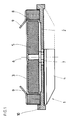
- bottom of the watch case is part of the Module itself forms and the central pin for that Bearings of the flywheel and the generator rotor.
- module 1 has one Mounting plate 2 on the top of the Generator 3 and on the underside the flywheel 4 wearing.
- the rotor 5 of the generator and the flywheel 4 are attached to a central pivot 6, the in a ball bearing 7 of the mounting plate 2 rotatable is stored.
- the permanent magnet or the magnetized rotor 5 is from the stator 8 surrounded, which has a ring coil.
- the two output terminals of the generator are made by two spring contacts 9 formed, which in the unloaded state point diagonally outwards.
- the mounting plate 2 is with one for clamping the module in the watch case provided certain ring flange 10.
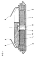
- FIGS 2 and 3 show a first embodiment a wristwatch with a module 1 Figure 1.
- the case of this watch consists of a Middle housing part 11, the top through a watch glass 13th is locked, and from a floor 12.
- a clockwork 14 is held by the middle part 11 and carries a Dial 15.
- module 1 arranged, which on its upper side Generator 3 with rotor 5 and stator 8 and on it lower side has the flywheel 4, with a screw 4a at the lower end of the pivot 6 ( Figure 1) is attached.
- the module 1 is with its ring flange 10 in a recess 11a of the Middle part 11 is used and is closed when the Housing by pressing the bottom 12 in the Middle part 11 clamped automatically.
- the Attachment of the clockwork 14 and the arrangement of the Turning 11a are chosen so that between the Clockwork 14 and module 1 there is a free space, so that the movement 14 in no way through the module 1 is mechanically loaded.
- a rechargeable one Power source preferably a rechargeable battery 16 which in the usual manner in a recess of the Clockwork 14 is arranged.
- the required Electronics or the required electronic Components are, preferably on a circuit board and / or an integrated circuit, housed in module 1, can also in a movement holder ring or housing ring, that shown in the example according to FIGS. 6 and 7 is installed.
- Figures 4 and 5 show a bottom 12, the for a second example of an otherwise not shown Small clock heard and on his up directed edge has a recess 12a, in which the module 1 with its ring flange 10 is inserted. If the watch case with this bottom 12 is closed, the ring flange 10 of the module pressed against the underside of the middle part of the housing and pinched. Again, the arrangement is like this hit that the top of module 1 where itself Rotor 5, stator 8 and spring contacts 9 are one has a certain distance from the clockwork. Likewise, the bottom has of module 1, where the flywheel 4 a certain distance from the floor 12.
- module 1 consists of the housing base 18, which is also the mounting plate forms the generator 3 with rotor 5 and stator 8 and the one arranged above the generator Inertia 4.
- a pin 19 molded or attached around which the movable Parts of module 1, namely rotor 5 and flywheel 4 are rotatably supported by means of a ball bearing 20.
- contact springs 9 With the terminals of the ring coil of the stator 8 connected contact springs 9 are bent in this case that they pass the flywheel 4 laterally protrude diagonally upwards.
- This module 1 with the bottom 18th can be pressed directly into a middle part of the housing be, as in Figure 9 using the example of a wristwatch shown.
- This watch has a central housing part 11 a lower recess 11a for module 1, one Movement holder ring 21 or housing ring which holds the movement 14 holds, has a dial 15 and a glass 13. Again the top of the module 1 with the flywheel 4 one Distance from clockwork 14.
- the rechargeable battery that is arranged as in the clock of Figure 2 is not shown.
- module 1 can with different movements and cases Design can be combined directly, provided that it is standardized housing and standard movements, that have a prescribed diameter.
- the floor can also be made of glass. Instead of a floor that can be assembled by pressing in can also a floor with screw fastening may be provided.
- the current source can also be a capacitor.
- FIG. 10 shows a small clock with a one-piece housing shell 22, in the below the module 1 with its ring flange 10 in one Turning 22a is inserted and which through above a glass 13 is closed.
- the distance to Movement 14 above is the movement retaining movement holder ring or housing ring 23, of the ring flange 10 of the Module 1 jammed.
- the dial 13 is on the edge held by a height ring 24.
- the flywheel 4 of module 1, which in turn is provided with spring contacts 9 is located below.
- the battery in the clockwork is not shown
- the spacer can also be a spacer ring be made of metal or plastic, in particular resilient plastic, exists.
- the described Housings can also be pressed on Have frosted glass.
Landscapes
- Engineering & Computer Science (AREA)
- Power Engineering (AREA)
- Physics & Mathematics (AREA)
- General Physics & Mathematics (AREA)
- Connection Of Motors, Electrical Generators, Mechanical Devices, And The Like (AREA)
Description
Claims (10)
- Elektronische Kleinuhr mit einem in einem Gehäuse (11, 12) angeordneten Uhrwerk (14), mit einer das Uhrwerk speisenden, aufladbaren Stromquelle (16) und mit einem die Stromquelle aufladenden Generator (3), dessen Rotor (5) von einer Schwungmasse (4) antreibbar ist, dadurch gekennzeichnet, dass der Generator (3) und die Schwungmasse (4) als ein vom Uhrwerk (14) mechanisch unabhängiger Modul (1) ausgebildet sind, der zwischen dem Gehäuseboden (12) und dem Uhrwerk (14) angeordnet ist und beim Schliessen des Uhrgehäuses im Abstand vom Uhrwerk (14) gehalten wird.
- Elektronische Kleinuhr nach Anspruch 1, dadurch gekennzeichnet, dass das Gehäuse einen Gehäusemittelteil (11) und einen Boden (12) aufweist und dass der Modul (1) an seinem Umfang mit einem Ringflansch (10) versehen ist, der zwischen Gehäusemittelteil (11) und Boden (12) eingeklemmt ist.
- Elektronische Kleinuhr nach Anspruch 1, dadurch gekennzeichnet, dass das Gehäuse einen Gehäusemittelteil, in welchem ein Werkhalterring (17) eingesetzt ist, und einen Boden aufweist und dass der Modul (1) an seinem Umfang mit einem Ringflansch (10) versehen ist, welcher zwischen dem Werkhalterring (17) und dem Boden eingeklemmt ist.
- Elektronische Kleinuhr nach einem der Ansprüche 2 oder 3, dadurch gekennzeichnet, dass der Ringflansch (10) des Moduls (1) in einer Ausdrehung (11a; 17a) eines der beiden Teile, Gehäusemittelteil (11) oder Werkhalterring (17) liegt.
- Elektronische Kleinuhr nach Anspruch 1, dadurch gekennzeichnet, dass das Gehäuse einen Gehäusemittelteil (11) und einen Boden (18) aufweist und dass dieser Boden (18) einen Teil des Moduls (1) bildet, dessen Unterseite darstellt und den zentralen Lagerzapfen (19) trägt, um den die Schwungmasse (4) und der Rotor (5) des Generators (3) drehbar sind, wobei die Schwungmasse (4) vorzugsweise auf der Oberseite des Generators (3) angeordnet ist.
- Elektronische Kleinuhr mit einem in einem Gehäuse angeordneten Uhrwerk (14), mit einer das Uhrwerk speisenden, aufladbaren Stromquelle und mit einem diese Stromquelle aufladenden Generator, dessen Rotor von einer Schwungmasse antreibbar ist, dadurch gekennzeichnet, dass das Gehäuse aus einer Gehäuseschale (22) besteht, dass der Generator und die Schwungmasse als ein vom Uhrwerk (14) mechanisch unabhängiger Modul (1) ausgebildet sind, dass dieser Modul (1) in den Bodenteil der Gehäuseschale (22) eingesetzt ist, durch ein Abstandselement (23), zum Beispiel in Form eines Gehäuse- oder Abstandsringes, im Abstand vom Uhrwerk (14) gehalten wird und beim Verschliessen der Gehäuseschale an seinem Rande eingeklemmt wird.
- Elektronische Kleinuhr nach einem der Ansprüche 1 bis 4 oder 6, dadurch gekennzeichnet, dass der Modul (1) eine Montageplatte (2) mit einem den Ringflansch (10) bildenden Rand aufweist und dass der Generator (3) auf der einen Seite und die Schwungmasse (4) auf der anderen Seite dieser Montageplatte (2) angeordnet sind.
- Elektronische Kleinuhr nach einem der Ansprüche 1 bis 7, dadurch gekennzeichnet, dass die elektrische Verbindung zwischen dem Generator (3) und dem Uhrwerk (14) beim Schliessen des Uhrgehäuses durch Kontaktierung der Generatorklemmen, vorzugsweise in Form von Federkontakten (9), mit an die Pole der Stromquelle (16) angeschlossenen Kontakten erfolgt.
- Elektronische Kleinuhr nach einem der Ansprüche 1 bis 8, dadurch gekennzeichnet, dass die zur Aufladung der Stromquelle (16) erforderliche Elektronik bzw. erforderlichen elektronischen Bauelemente, insbesondere zum Gleichrichten und Stabilisieren des Stroms oder der Spannung, in Form einer Leiterplatte und/oder einer integrierten Schaltung im Modul (1) untergebracht sind.
- Elektronische Kleinuhr nach einem der Ansprüche 1 bis 8, dadurch gekennzeichnet, dass sie einen Werkhalterring bzw. Gehäusering (17; 21) aufweist und dass die zur Aufladung der Stromquelle (16) erforderliche Elektronik bzw. erforderlichen elektronischen Bauelemente, insbesondere zum Gleichrichten und Stabilisieren des Stroms oder der Spannung, in Form einer Leiterplatte und/oder einer integrierten Schaltung in diesem Werkhalterring bzw. Gehäusering (17; 21) untergebracht sind.
Applications Claiming Priority (2)
| Application Number | Priority Date | Filing Date | Title |
|---|---|---|---|
| CH157894 | 1994-05-20 | ||
| CH1578/94 | 1994-05-20 |
Publications (2)
| Publication Number | Publication Date |
|---|---|
| EP0683442A1 EP0683442A1 (de) | 1995-11-22 |
| EP0683442B1 true EP0683442B1 (de) | 1998-04-15 |
Family
ID=4213697
Family Applications (1)
| Application Number | Title | Priority Date | Filing Date |
|---|---|---|---|
| EP19950810316 Expired - Lifetime EP0683442B1 (de) | 1994-05-20 | 1995-05-11 | Elektronische Kleinuhr |
Country Status (3)
| Country | Link |
|---|---|
| EP (1) | EP0683442B1 (de) |
| DE (1) | DE59501881D1 (de) |
| HK (1) | HK1008151A1 (de) |
Families Citing this family (1)
| Publication number | Priority date | Publication date | Assignee | Title |
|---|---|---|---|---|
| EP1821163A3 (de) * | 2006-02-13 | 2012-06-13 | Ventura Watch SA | Uhr mit Generator |
Family Cites Families (6)
| Publication number | Priority date | Publication date | Assignee | Title |
|---|---|---|---|---|
| CH356412A (fr) * | 1959-08-08 | 1961-08-15 | Piquerez Sa Ervin | Boîte de montre contenant une source d'électricité disposée dans un évidement intérieur du fond |
| US4008566A (en) * | 1975-11-10 | 1977-02-22 | Mcclintock Richard D | Electronic watch generator |
| FR2349868A1 (fr) * | 1976-04-29 | 1977-11-25 | Horlogerie Cie Europ | Procede de fabrication d'une montre a pile, et montre resultant de l'execution de ce procede |
| CH632895B (fr) * | 1980-03-31 | Ebauchesfabrik Eta Ag | Dispositif de fixation et de prise de contact electrique d'une pile dans une montre. | |
| NL8203443A (nl) * | 1982-09-03 | 1984-04-02 | Petrus Matheus Josephus Knapen | Draagbare, batterij-gevoede inrichting, in het bijzonder een armband- oftewel polshorloge, waarvan de batterij door het dragen in opgeladen toestand wordt gehouden, dan wel wordt opgeladen. |
| DE59107118D1 (de) * | 1990-10-22 | 1996-02-01 | Gigandet Charles Sa | Armbanduhr |
-
1995
- 1995-05-11 EP EP19950810316 patent/EP0683442B1/de not_active Expired - Lifetime
- 1995-05-11 DE DE59501881T patent/DE59501881D1/de not_active Expired - Fee Related
-
1998
- 1998-06-26 HK HK98107095A patent/HK1008151A1/xx not_active IP Right Cessation
Also Published As
| Publication number | Publication date |
|---|---|
| DE59501881D1 (de) | 1998-05-20 |
| HK1008151A1 (en) | 1999-04-30 |
| EP0683442A1 (de) | 1995-11-22 |
Similar Documents
| Publication | Publication Date | Title |
|---|---|---|
| EP0483065B1 (de) | Armbanduhr | |
| DE60208408T2 (de) | Digitaler pulserzeuger | |
| DE60037238T2 (de) | Verfahren zum Anpassen des pulsierenden Drehmoments eines Energiegenerators | |
| DE3790276C2 (de) | Batteriefach | |
| EP0236467B1 (de) | Elektromotor | |
| DE69931868T2 (de) | Elektromagnetischer Wandler und elektronisches Gerät das diesen Wandler enthält | |
| DE2625725A1 (de) | Batteriegespeistes elektrisches geraet | |
| DE3300704A1 (de) | Elektromagnetischer wandler | |
| DE2854906C2 (de) | Elektronische Uhr mit Solarbatterie | |
| DE2000544C3 (de) | Mindestens eine elastische Kontaktzunge aufweisende Klemmvorrichtung für in batteriebetriebene Geräte einsetzbare Batterien | |
| EP0683442B1 (de) | Elektronische Kleinuhr | |
| DE2711316C3 (de) | Elektronische Uhr | |
| DE2802713A1 (de) | Summer | |
| DE2718025C2 (de) | Elektronische Armbanduhr | |
| DE3902353A1 (de) | Uhrwerk fuer eine elektrische uhr | |
| DE3105298A1 (de) | Stromversorgungsvorrichtung fuer netzunabhaengige verbraucher | |
| DE2751797A1 (de) | Elektrische uhr, insbesondere armbanduhr | |
| DE60306382T2 (de) | Adapter für ein tragbares elektronisches Gerät und Übertragungssystem zwischen diesen Bauteilen | |
| DE2732944A1 (de) | Uhr | |
| CH681267A5 (en) | Battery charging device for electronic wrist watch | |
| CH688496B5 (de) | Uhrwerk fuer eine analoge Armbanduhr.. | |
| DE3942397A1 (de) | Anordnung zur stromzufuhr zu einem mit einem elektrischen verbraucher versehenen zeiger | |
| DE2425622A1 (de) | Batteriebetriebenes, elektrisches kleingeraet, insbesondere elektrische armbanduhr | |
| DE10329978B4 (de) | Elektronischer Umdrehungszähler | |
| DE102006006810A1 (de) | Funkuhr |
Legal Events
| Date | Code | Title | Description |
|---|---|---|---|
| PUAI | Public reference made under article 153(3) epc to a published international application that has entered the european phase |
Free format text: ORIGINAL CODE: 0009012 |
|
| AK | Designated contracting states |
Kind code of ref document: A1 Designated state(s): CH DE FR GB IT LI |
|
| 17P | Request for examination filed |
Effective date: 19960417 |
|
| GRAG | Despatch of communication of intention to grant |
Free format text: ORIGINAL CODE: EPIDOS AGRA |
|
| 17Q | First examination report despatched |
Effective date: 19970828 |
|
| GRAG | Despatch of communication of intention to grant |
Free format text: ORIGINAL CODE: EPIDOS AGRA |
|
| GRAH | Despatch of communication of intention to grant a patent |
Free format text: ORIGINAL CODE: EPIDOS IGRA |
|
| GRAH | Despatch of communication of intention to grant a patent |
Free format text: ORIGINAL CODE: EPIDOS IGRA |
|
| GRAA | (expected) grant |
Free format text: ORIGINAL CODE: 0009210 |
|
| AK | Designated contracting states |
Kind code of ref document: B1 Designated state(s): CH DE FR GB IT LI |
|
| PG25 | Lapsed in a contracting state [announced via postgrant information from national office to epo] |
Ref country code: IT Free format text: LAPSE BECAUSE OF FAILURE TO SUBMIT A TRANSLATION OF THE DESCRIPTION OR TO PAY THE FEE WITHIN THE PRE;WARNING: LAPSES OF ITALIAN PATENTS WITH EFFECTIVE DATE BEFORE 2007 MAY HAVE OCCURRED AT ANY TIME BEFORE 2007. THE CORRECT EFFECTIVE DATE MAY BE DIFFERENT FROM THE ONE RECORDED.SCRIBED TIME-LIMIT Effective date: 19980415 |
|
| REG | Reference to a national code |
Ref country code: CH Ref legal event code: EP |
|
| REF | Corresponds to: |
Ref document number: 59501881 Country of ref document: DE Date of ref document: 19980520 |
|
| GBT | Gb: translation of ep patent filed (gb section 77(6)(a)/1977) |
Effective date: 19980430 |
|
| ET | Fr: translation filed | ||
| PLBE | No opposition filed within time limit |
Free format text: ORIGINAL CODE: 0009261 |
|
| STAA | Information on the status of an ep patent application or granted ep patent |
Free format text: STATUS: NO OPPOSITION FILED WITHIN TIME LIMIT |
|
| 26N | No opposition filed | ||
| PGFP | Annual fee paid to national office [announced via postgrant information from national office to epo] |
Ref country code: FR Payment date: 19990525 Year of fee payment: 5 |
|
| PG25 | Lapsed in a contracting state [announced via postgrant information from national office to epo] |
Ref country code: FR Free format text: LAPSE BECAUSE OF NON-PAYMENT OF DUE FEES Effective date: 20010131 |
|
| REG | Reference to a national code |
Ref country code: FR Ref legal event code: ST |
|
| PGFP | Annual fee paid to national office [announced via postgrant information from national office to epo] |
Ref country code: GB Payment date: 20010509 Year of fee payment: 7 |
|
| PGFP | Annual fee paid to national office [announced via postgrant information from national office to epo] |
Ref country code: DE Payment date: 20010528 Year of fee payment: 7 |
|
| REG | Reference to a national code |
Ref country code: GB Ref legal event code: IF02 |
|
| PG25 | Lapsed in a contracting state [announced via postgrant information from national office to epo] |
Ref country code: GB Free format text: LAPSE BECAUSE OF NON-PAYMENT OF DUE FEES Effective date: 20020511 |
|
| PG25 | Lapsed in a contracting state [announced via postgrant information from national office to epo] |
Ref country code: DE Free format text: LAPSE BECAUSE OF NON-PAYMENT OF DUE FEES Effective date: 20021203 |
|
| GBPC | Gb: european patent ceased through non-payment of renewal fee |
Effective date: 20020511 |
|
| PGFP | Annual fee paid to national office [announced via postgrant information from national office to epo] |
Ref country code: CH Payment date: 20030528 Year of fee payment: 9 |
|
| PG25 | Lapsed in a contracting state [announced via postgrant information from national office to epo] |
Ref country code: LI Free format text: LAPSE BECAUSE OF NON-PAYMENT OF DUE FEES Effective date: 20040531 Ref country code: CH Free format text: LAPSE BECAUSE OF NON-PAYMENT OF DUE FEES Effective date: 20040531 |
|
| REG | Reference to a national code |
Ref country code: CH Ref legal event code: PL |