EP0683442B1 - Small electronic watch - Google Patents
Small electronic watch Download PDFInfo
- Publication number
- EP0683442B1 EP0683442B1 EP19950810316 EP95810316A EP0683442B1 EP 0683442 B1 EP0683442 B1 EP 0683442B1 EP 19950810316 EP19950810316 EP 19950810316 EP 95810316 A EP95810316 A EP 95810316A EP 0683442 B1 EP0683442 B1 EP 0683442B1
- Authority
- EP
- European Patent Office
- Prior art keywords
- casing
- watch
- module
- generator
- power source
- Prior art date
- Legal status (The legal status is an assumption and is not a legal conclusion. Google has not performed a legal analysis and makes no representation as to the accuracy of the status listed.)
- Expired - Lifetime
Links
Images


Classifications
-
- G—PHYSICS
- G04—HOROLOGY
- G04C—ELECTROMECHANICAL CLOCKS OR WATCHES
- G04C10/00—Arrangements of electric power supplies in time pieces
Definitions
- the invention relates to an electronic Watch with one arranged in a housing Clockwork, with a rechargeable that feeds the clockwork Power source and a charging this power source Generator, the rotor of a flywheel is drivable.
- Such a small watch in the form of a wristwatch is known from DE-A-2751 797 and has as Power source a small accumulator and one Generator, whose moving part with a through the movement of the clock actuatable inertial rotor as Flywheel is coupled.
- This flywheel is in a central point of a board, which is also the Power source carries, stored and at its edge provided with a permanent magnet.
- This Permanent magnet works with fixedly installed coils together, on the moving circle of the permanent magnet lie. The current pulses induced in this way are rectified by a rectifier circuit and to charge the small accumulator used.
- the generator the flywheel and the movement inside the case are mounted in this publication nothing said.
- the present invention is based on the object an electronic watch of the type described at the beginning Kind of train so that from generator and flywheel existing component in a simple manner, without interfering with the movement, quickly in the watch case can be mounted without the pressure sensitive electronic clockwork when assembling the watch is mechanically stressed by the mentioned component becomes; the generator and Flywheel existing component for housing and Movements of different types without constructive Change may be applicable, provided that these are Watch cases around standard cases with the same opening diameter acts.
- bottom of the watch case is part of the Module itself forms and the central pin for that Bearings of the flywheel and the generator rotor.
- module 1 has one Mounting plate 2 on the top of the Generator 3 and on the underside the flywheel 4 wearing.
- the rotor 5 of the generator and the flywheel 4 are attached to a central pivot 6, the in a ball bearing 7 of the mounting plate 2 rotatable is stored.
- the permanent magnet or the magnetized rotor 5 is from the stator 8 surrounded, which has a ring coil.
- the two output terminals of the generator are made by two spring contacts 9 formed, which in the unloaded state point diagonally outwards.
- the mounting plate 2 is with one for clamping the module in the watch case provided certain ring flange 10.
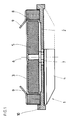
- FIGS 2 and 3 show a first embodiment a wristwatch with a module 1 Figure 1.
- the case of this watch consists of a Middle housing part 11, the top through a watch glass 13th is locked, and from a floor 12.
- a clockwork 14 is held by the middle part 11 and carries a Dial 15.
- module 1 arranged, which on its upper side Generator 3 with rotor 5 and stator 8 and on it lower side has the flywheel 4, with a screw 4a at the lower end of the pivot 6 ( Figure 1) is attached.
- the module 1 is with its ring flange 10 in a recess 11a of the Middle part 11 is used and is closed when the Housing by pressing the bottom 12 in the Middle part 11 clamped automatically.
- the Attachment of the clockwork 14 and the arrangement of the Turning 11a are chosen so that between the Clockwork 14 and module 1 there is a free space, so that the movement 14 in no way through the module 1 is mechanically loaded.
- a rechargeable one Power source preferably a rechargeable battery 16 which in the usual manner in a recess of the Clockwork 14 is arranged.
- the required Electronics or the required electronic Components are, preferably on a circuit board and / or an integrated circuit, housed in module 1, can also in a movement holder ring or housing ring, that shown in the example according to FIGS. 6 and 7 is installed.
- Figures 4 and 5 show a bottom 12, the for a second example of an otherwise not shown Small clock heard and on his up directed edge has a recess 12a, in which the module 1 with its ring flange 10 is inserted. If the watch case with this bottom 12 is closed, the ring flange 10 of the module pressed against the underside of the middle part of the housing and pinched. Again, the arrangement is like this hit that the top of module 1 where itself Rotor 5, stator 8 and spring contacts 9 are one has a certain distance from the clockwork. Likewise, the bottom has of module 1, where the flywheel 4 a certain distance from the floor 12.
- module 1 consists of the housing base 18, which is also the mounting plate forms the generator 3 with rotor 5 and stator 8 and the one arranged above the generator Inertia 4.
- a pin 19 molded or attached around which the movable Parts of module 1, namely rotor 5 and flywheel 4 are rotatably supported by means of a ball bearing 20.
- contact springs 9 With the terminals of the ring coil of the stator 8 connected contact springs 9 are bent in this case that they pass the flywheel 4 laterally protrude diagonally upwards.
- This module 1 with the bottom 18th can be pressed directly into a middle part of the housing be, as in Figure 9 using the example of a wristwatch shown.
- This watch has a central housing part 11 a lower recess 11a for module 1, one Movement holder ring 21 or housing ring which holds the movement 14 holds, has a dial 15 and a glass 13. Again the top of the module 1 with the flywheel 4 one Distance from clockwork 14.
- the rechargeable battery that is arranged as in the clock of Figure 2 is not shown.
- module 1 can with different movements and cases Design can be combined directly, provided that it is standardized housing and standard movements, that have a prescribed diameter.
- the floor can also be made of glass. Instead of a floor that can be assembled by pressing in can also a floor with screw fastening may be provided.
- the current source can also be a capacitor.
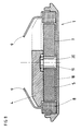
- FIG. 10 shows a small clock with a one-piece housing shell 22, in the below the module 1 with its ring flange 10 in one Turning 22a is inserted and which through above a glass 13 is closed.
- the distance to Movement 14 above is the movement retaining movement holder ring or housing ring 23, of the ring flange 10 of the Module 1 jammed.
- the dial 13 is on the edge held by a height ring 24.
- the flywheel 4 of module 1, which in turn is provided with spring contacts 9 is located below.
- the battery in the clockwork is not shown
- the spacer can also be a spacer ring be made of metal or plastic, in particular resilient plastic, exists.
- the described Housings can also be pressed on Have frosted glass.
Description
Die Erfindung bezieht sich auf eine elektronische Kleinuhr mit einem in einem Gehäuse angeordneten Uhrwerk, mit einer das Uhrwerk speisenden, aufladbaren Stromquelle und einem diese Stromquelle aufladenden Generator, dessen Rotor von einer Schwungmasse antreibbar ist.The invention relates to an electronic Watch with one arranged in a housing Clockwork, with a rechargeable that feeds the clockwork Power source and a charging this power source Generator, the rotor of a flywheel is drivable.
Eine derartige Kleinuhr in Form einer Armbanduhr ist aus der DE-A- 2751 797 bekannt und weist als Stromquelle einen Kleinakkumulator sowie einen Generator auf, dessen beweglicher Teil mit einem durch die Bewegung der Uhr betätigbaren Trägheitsrotor als Schwungmasse gekuppelt ist. Diese Schwungmasse ist in einem zentralen Punkt einer Platine, welche auch die Stromquelle trägt, gelagert und an ihrem Randbereich mit einem aufgeklebten Dauermagneten versehen. Dieser Dauermagnet wirkt mit ortsfest installierten Spulen zusammen, die auf dem Bewegungskreis des Dauermagneten liegen. Die auf diese Weise induzierten Stromimpulse werden durch eine Gleichrichterschaltung gleichgerichtet und zum Laden des Kleinakkumulators verwendet. Ueber die Art und Weise, wie der Generator, die Schwungmasse und das Uhrwerk innerhalb des Gehäuses montiert sind, wird in dieser Druckschrift nichts gesagt.Such a small watch in the form of a wristwatch is known from DE-A-2751 797 and has as Power source a small accumulator and one Generator, whose moving part with a through the movement of the clock actuatable inertial rotor as Flywheel is coupled. This flywheel is in a central point of a board, which is also the Power source carries, stored and at its edge provided with a permanent magnet. This Permanent magnet works with fixedly installed coils together, on the moving circle of the permanent magnet lie. The current pulses induced in this way are rectified by a rectifier circuit and to charge the small accumulator used. About the way the generator the flywheel and the movement inside the case are mounted in this publication nothing said.
Aus der CH-B- 679 358 ist ein durch eine Schwungmasse antreibbarer Generator in Form eines zusammenhängenden Bauteils bekannt, welches zum Einbau in eine elektronische Kleinuhr zwecks Aufladung eines Kondensators als Stromquelle bestimmt ist. Ueber die Art und Weise, wie Generator und Uhrwerk im Uhrgehäuse eingebaut sind, wird in dieser Druckschrift nichts ausgesagt. From CH-B-679 358 one by one Flywheel driven generator in the form of a coherent Known component, which for installation in a small electronic clock for charging a capacitor is intended as a power source. About Art and how generator and clockwork in the watch case are built in, nothing in this publication testified.
Aus der PCT-Veröffentlichung WO 92/04662 ist ebenfalls ein durch eine Schwungmasse antreibbarer Generator zum Einbau in eine elektronische Kleinuhr bekannt, wobei Generator und Schwungmasse in einem besonderen, im wesentlichen geschlossenen Gehäuse mit rechteckförmigem Querschnitt untergebracht sind. Ueber den Einbau dieses Generatorgehäuses und des Uhrwerks in einem Uhrgehäuse wird in dieser Druckschrift nicht ausgesagt.From PCT publication WO 92/04662 also a driven by a flywheel Generator for installation in an electronic watch known, with generator and flywheel in a special, essentially closed housing with rectangular cross-section are housed. Over the installation of this generator housing and the clockwork in a watch case is not stated in this document.
Der vorliegenden Erfindung liegt die Aufgabe zugrunde, eine elektronische Kleinuhr der anfangs beschriebenen Art so auszubilden, dass das aus Generator und Schwungmasse bestehende Bauteil auf einfache Weise, ohne Eingriff in das Uhrwerk, rasch im Uhrgehäuse montiert werden kann, ohne dass das gegen Druck empfindliche elektronische Uhrwerk beim Zusammenbauen der Uhr durch das erwähnte Bauteil mechanisch belastet wird; gleichzeitig soll das aus Generator und Schwungmasse bestehende Bauteil für Gehäuse und Uhrwerke unterschiedlicher Bauart ohne konstruktive Veränderung anwendbar sein, sofern es sich bei diesen Uhrgehäusen um Standardgehäuse mit gleichem Oeffnungsdurchmesser handelt.The present invention is based on the object an electronic watch of the type described at the beginning Kind of train so that from generator and flywheel existing component in a simple manner, without interfering with the movement, quickly in the watch case can be mounted without the pressure sensitive electronic clockwork when assembling the watch is mechanically stressed by the mentioned component becomes; the generator and Flywheel existing component for housing and Movements of different types without constructive Change may be applicable, provided that these are Watch cases around standard cases with the same opening diameter acts.
Diese Aufgabe wird erfindungsgemäss durch die im
kennzeichnenden Teil des Patentanspruchs 1 und des Patentanspruchs
6 angegebenen Merkmale gelöst.This object is achieved by the im
characterizing part of
Dadurch wird erreicht, dass der vorgefertigte Modul einfach, ähnlich wie die vorgefertigten, auf dem Markt erhältlichen Uhrwerke, in das offene Gehäuse eingelegt und beim Schliessen des Gehäuses durch Klemmung fixiert wird. Vorzugsweise findet beim Schliessen des Gehäuses selbsttätig die erforderliche elektrische Kontaktierung zwischen den Generatorklemmen und den Polen der Stromquelle statt, indem die entsprechenden metallischen Teile miteinander in Berührung gebracht werden, ohne dass besondere elektrische Leitungselemente zwischen Generator und Stromquelle installiert werden müssten.This ensures that the prefabricated Module simple, similar to the prefabricated, on the Market movements available in the open case inserted and when closing the housing Clamp is fixed. Preferably takes place at Closing the housing automatically the required electrical contact between the generator terminals and the poles of the power source instead by the corresponding metallic parts with each other Be brought in touch without anything special electrical conduction elements between generator and Power source would have to be installed.
In einer bevorzugten Ausführungsform ist der Modul an seinem Umfang mit einem Ringflansch versehen, welcher in eine entsprechende Ausdrehung des Gehäusemittelteils oder, wenn die Uhr einen Werkhalterring hat, in eine entsprechende Ausdrehung des Werkhalterrings eingelegt und beim Schliessen des Gehäuses durch den Boden eingeklemmt wird.In a preferred embodiment, the Provide the module with a ring flange on its circumference, which in a corresponding turn of the middle part of the housing or if the watch has a movement holder ring in a corresponding recess of the movement holder ring inserted and when closing the housing is pinched by the floor.
Eine weitere bevorzugte Ausführungsform besteht darin, dass der Boden des Uhrgehäuses einen Teil des Moduls selber bildet und den zentralen Zapfen für das Lager der Schwungmasse und des Generatorrotors trägt.Another preferred embodiment exists in that the bottom of the watch case is part of the Module itself forms and the central pin for that Bearings of the flywheel and the generator rotor.
Zweckmässige weitere Ausbildungen der Erfindung ergeben sich aus den abhängigen Ansprüchen.Appropriate further developments of the invention result from the dependent claims.
Die Erfindung wird anhand der Zeichnungen an Ausführungsbeispielen näher erläutert.The invention is based on the drawings Exemplary embodiments explained in more detail.
Es zeigen :
Nach Figur 1 weist der Modul 1 eine
Montageplatte 2 auf, die auf der Oberseite den
Generator 3 und auf der Unterseite die Schwungmasse 4
trägt. Der Rotor 5 des Generators und die Schwungmasse
4 sind an einem zentralen Drehzapfen 6 befestigt, der
in einem Kugellager 7 der Montageplatte 2 drehbar
gelagert ist. Der mit Dauermagneten versehene oder
entsprechend magnetisierte Rotor 5 ist vom Stator 8
umgeben, der eine Ringspule aufweist. Die beiden Ausgangsklemmen
des Generators werden von zwei Federkontakten
9 gebildet, welche im nicht belasteten Zustand
schräg nach aussen weisen. Die Montageplatte 2
ist mit einem zum Einklemmen des Moduls im Uhrgehäuse
bestimmten Ringflansch 10 versehen.According to FIG. 1,
Die Figuren 2 und 3 zeigen ein erstes Ausführungsbeispiel
einer Armbanduhr mit einem Modul 1 nach
Figur 1. Das Gehäuse dieser Uhr besteht aus einem
Gehäusemittelteil 11, der oben durch ein Uhrglas 13
verschlossen ist, und aus einem Boden 12. Ein Uhrwerk
14 wird vom Gehäusemittelteil 11 gehalten und trägt ein
Zifferblatt 15. Zwischen dem Uhrwerk 14 und dem Boden
12 ist, im Abstand vom Uhrwerk 14, der Modul 1
angeordnet, welcher auf seiner oberen Seite den
Generator 3 mit Rotor 5 und Stator 8 und auf seiner
unteren Seite die Schwungmasse 4 aufweist, die mit
einer Schraube 4a am unteren Ende des Drehzapfens 6
(Figur 1) befestigt ist.Figures 2 and 3 show a first embodiment
a wristwatch with a
Wie in Figur 2 gezeigt, ist der Modul 1 mit
seinem Ringflansch 10 in einer Ausdrehung 11a des
Mittelteils 11 eingesetzt und wird beim Schliessen des
Gehäuses durch Einpressen des Bodens 12 in den
Mittelteil 11 selbsttätig festgeklemmt. Die
Befestigung des Uhrwerks 14 und die Anordnung der
Ausdrehung 11a sind so gewählt, dass zwischen dem
Uhrwerk 14 und dem Modul 1 ein freier Raum besteht,
sodass das Uhrwerk 14 in keiner Weise durch den Modul 1
mechanisch belastet wird. Ebenso befindet sich die
Unterseite des Moduls mit der Schwungmasse 4 im Abstand
vom Boden 12. Beim Einsetzen des Moduls 1 bzw. beim
Verschliessen des Gehäuses mit dem Boden 12 erfolgt
selbsttätig die erforderliche elektrische Kontaktierung
zwischen den Generatorklemmen und einer aufladbaren
Stromquelle, vorzugsweise einer aufladbaren Batterie
16, die in üblicher Weise in einer Ausnehmung des
Uhrwerks 14 angeordnet ist. Dabei berührt die eine der
Kontaktfedern 9 den an Masse liegenden Pol der
Batterie, gewöhnlich den aussen liegenden Pluspol, und
die andere Kontaktfeder 9 einen an der Unterseite des
Uhrwerks 14 zugänglichen Kontakt, der mit dem anderen
Pol der Batterie in leitender Verbindung steht.As shown in Figure 2, the
Bei einer Bewegung der Uhr wird die Schwungmasse
4 des Moduls, und damit der Rotor 3 des Generators in
Drehung versetzt, sodass die längs des Umfangs des
Rotors befindlichen Magnete vor der Ringspule des
Stators 8 bewegt werden, wodurch in bekannter Weise
Stromimpulse erzeugt werden, die nach Gleichrichtung
zum Aufladen der Batterie 16 dienen. Die erforderliche
Elektronik bzw. die erforderlichen elektronischen
Komponenten, insbesondere zum Gleichrichten und
Stabilisieren des induzierten Stroms oder der Spannung,
sind, vorzugsweise auf einer Leiterplatte und/oder
einer integrierten Schaltung, im Modul 1 untergebracht,
können aber auch in einem Werkhalterring bzw. Gehäusering,
der im Beispiel nach den Figuren 6 und 7 gezeigt
ist, installiert sein.When the clock moves, the
Die Figuren 4 und 5 zeigen einen Boden 12, der
zu einem zweiten Beispiel einer sonst nicht näher dargestellten
Kleinuhr gehört und an seinem nach oben
gerichteten Rand eine Ausdrehung 12a aufweist, in
welcher der Modul 1 mit seinem Ringflansch 10
eingesetzt ist. Wenn das Uhrgehäuse mit diesem Boden 12
verschlossen wird, wird der Ringflansch 10 des Moduls
gegen die Unterseite des Gehäusemittelteils gedrückt
und eingeklemmt. Wiederum ist die Anordnung so
getroffen, dass die Oberseite des Moduls 1, wo sich
Rotor 5, Stator 8 und Federkontakte 9 befinden, einen
gewissen Abstand vom Uhrwerk hat. Ebenso hat die Unterseite
des Moduls 1, wo sich die Schwungmasse 4
befindet, einen gewissen Abstand zum Boden 12.Figures 4 and 5 show a
Im Beispiel nach den Figuren 6 und 7 ist
angenommen, dass das nicht dargestellte Uhrgehäuse mit
einem inneren Werkhalterring 17 oder Gehäusering
versehen ist, der in üblicher Weise das nicht
dargestellte Uhrwerk trägt. In diesem Falle hat der
Werkhalterring 17 auf der Unterseite eine Ausdrehung
17a, in welcher der Modul 1 mit seinem Ringflansch 10
eingesetzt ist. Wenn das Gehäuse zusammengebaut wird,
drückt der Boden mit einem nach oben gerichteten Rand,
wie beim Beispiel nach Figur 2, gegen den Ringflansch
10 und klemmt so den Modul 1 fest. Wiederum befindet
sich die Oberseite des Moduls 1 mit Rotor 5, Stator 8
und Kontaktfedern 9 im Abstand vom Uhrwerk, und die
Unterseite des Moduls 1 mit der Schwungmasse 4 befindet
sich im Abstand vom Boden.In the example according to FIGS. 6 and 7
assumed that the watch case, not shown, with
an inner
Im Beispiel nach Figur 8 besteht der Modul 1 aus
dem Gehäuseboden 18, der gleichzeitig die Montageplatte
bildet, dem Generator 3 mit Rotor 5 und Stator 8
sowie der oberhalb des Generators angeordneten
Schwungmasse 4. Im Zentrum des Bodens 18 ist ein Zapfen
19 angeformt oder befestigt, um welchen die beweglichen
Teile des Moduls 1, nämlich Rotor 5 und Schwungmasse 4
mittels eines Kugellagers 20 drehbar gelagert sind.
Die mit den Klemmen der Ringspule des Stators 8
verbundenen Kontaktfedern 9 sind in diesem Falle so gebogen,
dass sie seitlich an der Schwungmasse 4 vorbei
schräg nach oben ragen. Dieser Modul 1 mit dem Boden 18
kann direkt in ein Gehäusemittelteil eingepresst
werden, wie in Figur 9 am Beispiel einer Armbanduhr
gezeigt. Diese Uhr hat ein Gehäusemittelteil 11 mit
einer unteren Ausdrehung 11a für den Modul 1, einen
Werkhalterring 21 oder Gehäusering, der das Uhrwerk 14
hält, ein Zifferblatt 15 und ein Glas 13. Wiederum hat
die Oberseite des Moduls 1 mit der Schwungmasse 4 einen
Abstand vom Uhrwerk 14. Die aufladbare Batterie, die
wie bei der Uhr nach Figur 2 angeordnet ist, ist nicht
gezeigt.In the example according to FIG. 8,
Die beschriebenen Ausführungsformen des Moduls 1
können mit Uhrwerken und Gehäusen unterschiedlicher
Bauart direkt kombiniert werden, sofern es sich um
standardisierte Gehäuse und Standarduhrwerke handelt,
die einen vorgeschriebenen Durchmesser haben.The described embodiments of
Der Boden kann auch aus Glas bestehen. Anstelle eines durch Einpressen montierbaren Bodens kann auch ein Boden mit Schraubbefestigung vorgesehen sein. Die Stromquelle kann auch ein Kondensator sein. The floor can also be made of glass. Instead of a floor that can be assembled by pressing in can also a floor with screw fastening may be provided. The The current source can also be a capacitor.
Das Beispiel nach Figur 10 zeigt eine Kleinuhr
mit einer einteiligen Gehäuseschale 22, in die unten
der Modul 1 mit seinem Ringflansch 10 in eine
Ausdrehung 22a eingesetzt ist und welche oben durch
ein Glas 13 verschlossen ist. Der Abstand zum
darüberliegenden Uhrwerk 14 wird durch einen das Uhrwerk
haltenden Werkhalterring bzw. Gehäusering 23 gewährleistet,
der gleichzeitig den Ringflansch 10 des
Moduls 1 einklemmt. Das Zifferblatt 13 wird am Rand
durch einen Höhenring 24 gehalten. Die Schwungmasse 4
des Moduls 1, der wiederum mit Federkontakten 9 versehen
ist, befindet sich unten. Die Batterie im Uhrwerk
ist nicht gezeigt.dsThe example according to FIG. 10 shows a small clock
with a one-
Das Abstandselement kann auch ein Abstandsring sein, der aus Metall oder Kunststoff, insbesondere elastisch nachgiebigem Kunststoff, besteht. Die beschriebenen Gehäuse können auch einen aufgepressten Glasreif haben.The spacer can also be a spacer ring be made of metal or plastic, in particular resilient plastic, exists. The described Housings can also be pressed on Have frosted glass.
Claims (10)
- An electronic watch having a watch mechanism (14) arranged in a casing (11, 12), having a chargeable power source (16) feeding the watch mechanism and having a generator (3) which charges the power source and the rotor (5) of which can be driven by a flywheel mass (4), wherein the generator (3) and the flywheel mass (4) are formed as a module (1) which is mechanically independent of the watch mechanism (14), is arranged between the casing base (12) and the watch mechanism (14) and is kept at a distance from the watch mechanism (14) when the watch casing is closed.
- The electronic watch as claimed in claim 1, wherein the casing has a casing center part (11) and a base (12) and wherein the module (1) is provided on its circumference with an annular flange (10), which is clamped in between the casing center part (11) and the base (12).
- The electronic watch as claimed in claim 1, wherein the casing has a casing center part, in which a mechanism retaining ring (17) is inserted, and a base and wherein the module (1) is provided on its circumference with an annular flange (10), which is clamped in between the mechanism retaining ring (17) and the base.
- The electronic watch as claimed in one of claims 2 or 3, wherein the annular flange (10) of the module (1) lies in a machined relief (11a; 17a) of one of the two parts, the casing center part (11) or the mechanism retaining ring (17).
- The electronic watch as claimed in claim 1, wherein the casing has a casing center part (11) and a base (18) and wherein this base (18) forms part of the module (1), represents the underside of the latter and bears the central bearing pin (19), about which the flywheel mass (4) and the rotor (5) of the generator (3) are rotatable, the flywheel mass (4) being preferably arranged on the upper side of the generator (3).
- An electronic watch having a watch mechanism (14) arranged in a casing, having a chargeable power source feeding the watch mechanism and having a generator which charges this power source and the rotor of which can be driven by a flywheel mass, wherein the casing comprises a casing shell (22), wherein the generator and the flywheel mass are formed as a module (1) mechanically independent of the watch mechanism (14), wherein this module (1) is inserted into the base part of the casing shell (22), is kept at a distance from the watch mechanism (14) by a spacing element (23), for example in the form of a casing ring or spacer ring, and is clamped in at its rim when the casing shell is closed.
- The electronic watch as claimed in one of claims 1 to 4 or 6, wherein the module (1) has a mounting plate (2) with an rim forming the annular flange (10) and wherein the generator (3) is arranged on one side and the flywheel mass (4) is arranged on the other side of the mounting plate (2).
- The electronic watch as claimed in one of claims 1 to 7, wherein the electrical connection between the generator (3) and the watch mechanism (14) takes place when the watch casing is closed by contacts being made between the generator terminals, preferably in the form of spring contacts (9), and contacts connected to the poles of the power source (16).
- The electronic watch as claimed in one of claims 1 to 8, wherein the electronics required for charging the power source (16), or the required electronic components, in particular for rectifying and stabilizing the current or the voltage, are accommodated in the module (1) in the form of a printed-circuit board and/or an integrated circuit.
- The electronic watch as claimed in one of claims 1 to 8, wherein it has a mechanism retaining ring or casing ring (17; 21) and wherein the electronics required for charging the power source (16), or the required electronic components, in particular for rectifying and stabilizing the current or the voltage, are accommodated in this mechanism retaining ring or casing ring (17; 21) in the form of a printed-circuit board and/or an integrated circuit.
Applications Claiming Priority (2)
| Application Number | Priority Date | Filing Date | Title |
|---|---|---|---|
| CH1578/94 | 1994-05-20 | ||
| CH157894 | 1994-05-20 |
Publications (2)
| Publication Number | Publication Date |
|---|---|
| EP0683442A1 EP0683442A1 (en) | 1995-11-22 |
| EP0683442B1 true EP0683442B1 (en) | 1998-04-15 |
Family
ID=4213697
Family Applications (1)
| Application Number | Title | Priority Date | Filing Date |
|---|---|---|---|
| EP19950810316 Expired - Lifetime EP0683442B1 (en) | 1994-05-20 | 1995-05-11 | Small electronic watch |
Country Status (3)
| Country | Link |
|---|---|
| EP (1) | EP0683442B1 (en) |
| DE (1) | DE59501881D1 (en) |
| HK (1) | HK1008151A1 (en) |
Families Citing this family (1)
| Publication number | Priority date | Publication date | Assignee | Title |
|---|---|---|---|---|
| EP1821163A3 (en) * | 2006-02-13 | 2012-06-13 | Ventura Watch SA | Timepiece with generator |
Family Cites Families (6)
| Publication number | Priority date | Publication date | Assignee | Title |
|---|---|---|---|---|
| CH356412A (en) * | 1959-08-08 | 1961-08-15 | Piquerez Sa Ervin | Watch box containing a source of electricity arranged in a recess inside the back |
| US4008566A (en) * | 1975-11-10 | 1977-02-22 | Mcclintock Richard D | Electronic watch generator |
| FR2349868A1 (en) * | 1976-04-29 | 1977-11-25 | Horlogerie Cie Europ | Slim-line battery operated watch - has circuit module superimposed on battery and held by frame ring |
| CH632895B (en) * | 1980-03-31 | Ebauchesfabrik Eta Ag | DEVICE FOR FIXING AND ELECTRICAL CONTACT OF A BATTERY IN A WATCH. | |
| NL8203443A (en) * | 1982-09-03 | 1984-04-02 | Petrus Matheus Josephus Knapen | PORTABLE, BATTERY-POWERED DEVICE, IN PARTICULAR A BRACELET OR WRIST WATCH, WHOSE BATTERY IS KEPT IN CHARGED CONDITION WHEN CHARGED. |
| DE59107118D1 (en) * | 1990-10-22 | 1996-02-01 | Gigandet Charles Sa | Wrist watch |
-
1995
- 1995-05-11 DE DE59501881T patent/DE59501881D1/en not_active Expired - Fee Related
- 1995-05-11 EP EP19950810316 patent/EP0683442B1/en not_active Expired - Lifetime
-
1998
- 1998-06-26 HK HK98107095A patent/HK1008151A1/en not_active IP Right Cessation
Also Published As
| Publication number | Publication date |
|---|---|
| EP0683442A1 (en) | 1995-11-22 |
| HK1008151A1 (en) | 1999-04-30 |
| DE59501881D1 (en) | 1998-05-20 |
Similar Documents
| Publication | Publication Date | Title |
|---|---|---|
| EP0483065B1 (en) | Wristwatch | |
| DE60208408T2 (en) | DIGITAL POWDER PRODUCER | |
| DE3790276C2 (en) | Receptacle for housing batteries in camera | |
| EP0236467B1 (en) | Electric motor | |
| DE69931868T2 (en) | Electromagnetic transducer and electronic device containing this transducer | |
| EP0851322B1 (en) | Micro-generator, module and time piece, containing such a micro-generator | |
| DE3300704A1 (en) | ELECTROMAGNETIC CONVERTER | |
| DE2854906C2 (en) | Electronic clock with solar battery | |
| DE2000544C3 (en) | At least one elastic contact tongue having clamping device for batteries that can be used in battery-operated devices | |
| EP0683442B1 (en) | Small electronic watch | |
| DE2711316C3 (en) | Electronic clock | |
| DE2802713A1 (en) | SUMMER | |
| DE2718025C2 (en) | Electronic wrist watch | |
| DE3105298A1 (en) | Power-supply device for loads which are independent of the mains | |
| DE2751797A1 (en) | Electrically driven wrist watch - has charging circuit with generator connected to inertia rotor operated by watch movement | |
| DE60306382T2 (en) | Adapter for a portable electronic device and transmission system between these components | |
| DE2732944A1 (en) | CLOCK | |
| DE4110984C2 (en) | Battery case | |
| CH681267A5 (en) | Battery charging device for electronic wrist watch | |
| DE10207399A1 (en) | Electrical rotary switch for adjusting angles of rotation has a rotor on a stator adjusting between angular rotary positions and moving a permanent magnetic field sensor and a Hall sensor to create a signal for an angle of rotation. | |
| DE2425622A1 (en) | BATTERY-OPERATED, SMALL ELECTRIC DEVICE, IN PARTICULAR ELECTRIC WRISTWATCH | |
| DE10329978B4 (en) | Electronic revolution counter | |
| DE102006006810A1 (en) | Radio Clock | |
| DE3047492A1 (en) | WATCH MOVEMENT ARRANGEMENT AND METHOD FOR PRODUCING THE SAME | |
| DE1952075A1 (en) | Power supply device for electronic pocket watches |
Legal Events
| Date | Code | Title | Description |
|---|---|---|---|
| PUAI | Public reference made under article 153(3) epc to a published international application that has entered the european phase |
Free format text: ORIGINAL CODE: 0009012 |
|
| AK | Designated contracting states |
Kind code of ref document: A1 Designated state(s): CH DE FR GB IT LI |
|
| 17P | Request for examination filed |
Effective date: 19960417 |
|
| GRAG | Despatch of communication of intention to grant |
Free format text: ORIGINAL CODE: EPIDOS AGRA |
|
| 17Q | First examination report despatched |
Effective date: 19970828 |
|
| GRAG | Despatch of communication of intention to grant |
Free format text: ORIGINAL CODE: EPIDOS AGRA |
|
| GRAH | Despatch of communication of intention to grant a patent |
Free format text: ORIGINAL CODE: EPIDOS IGRA |
|
| GRAH | Despatch of communication of intention to grant a patent |
Free format text: ORIGINAL CODE: EPIDOS IGRA |
|
| GRAA | (expected) grant |
Free format text: ORIGINAL CODE: 0009210 |
|
| AK | Designated contracting states |
Kind code of ref document: B1 Designated state(s): CH DE FR GB IT LI |
|
| PG25 | Lapsed in a contracting state [announced via postgrant information from national office to epo] |
Ref country code: IT Free format text: LAPSE BECAUSE OF FAILURE TO SUBMIT A TRANSLATION OF THE DESCRIPTION OR TO PAY THE FEE WITHIN THE PRE;WARNING: LAPSES OF ITALIAN PATENTS WITH EFFECTIVE DATE BEFORE 2007 MAY HAVE OCCURRED AT ANY TIME BEFORE 2007. THE CORRECT EFFECTIVE DATE MAY BE DIFFERENT FROM THE ONE RECORDED.SCRIBED TIME-LIMIT Effective date: 19980415 |
|
| REG | Reference to a national code |
Ref country code: CH Ref legal event code: EP |
|
| REF | Corresponds to: |
Ref document number: 59501881 Country of ref document: DE Date of ref document: 19980520 |
|
| GBT | Gb: translation of ep patent filed (gb section 77(6)(a)/1977) |
Effective date: 19980430 |
|
| ET | Fr: translation filed | ||
| PLBE | No opposition filed within time limit |
Free format text: ORIGINAL CODE: 0009261 |
|
| STAA | Information on the status of an ep patent application or granted ep patent |
Free format text: STATUS: NO OPPOSITION FILED WITHIN TIME LIMIT |
|
| 26N | No opposition filed | ||
| PGFP | Annual fee paid to national office [announced via postgrant information from national office to epo] |
Ref country code: FR Payment date: 19990525 Year of fee payment: 5 |
|
| PG25 | Lapsed in a contracting state [announced via postgrant information from national office to epo] |
Ref country code: FR Free format text: LAPSE BECAUSE OF NON-PAYMENT OF DUE FEES Effective date: 20010131 |
|
| REG | Reference to a national code |
Ref country code: FR Ref legal event code: ST |
|
| PGFP | Annual fee paid to national office [announced via postgrant information from national office to epo] |
Ref country code: GB Payment date: 20010509 Year of fee payment: 7 |
|
| PGFP | Annual fee paid to national office [announced via postgrant information from national office to epo] |
Ref country code: DE Payment date: 20010528 Year of fee payment: 7 |
|
| REG | Reference to a national code |
Ref country code: GB Ref legal event code: IF02 |
|
| PG25 | Lapsed in a contracting state [announced via postgrant information from national office to epo] |
Ref country code: GB Free format text: LAPSE BECAUSE OF NON-PAYMENT OF DUE FEES Effective date: 20020511 |
|
| PG25 | Lapsed in a contracting state [announced via postgrant information from national office to epo] |
Ref country code: DE Free format text: LAPSE BECAUSE OF NON-PAYMENT OF DUE FEES Effective date: 20021203 |
|
| GBPC | Gb: european patent ceased through non-payment of renewal fee |
Effective date: 20020511 |
|
| PGFP | Annual fee paid to national office [announced via postgrant information from national office to epo] |
Ref country code: CH Payment date: 20030528 Year of fee payment: 9 |
|
| PG25 | Lapsed in a contracting state [announced via postgrant information from national office to epo] |
Ref country code: LI Free format text: LAPSE BECAUSE OF NON-PAYMENT OF DUE FEES Effective date: 20040531 Ref country code: CH Free format text: LAPSE BECAUSE OF NON-PAYMENT OF DUE FEES Effective date: 20040531 |
|
| REG | Reference to a national code |
Ref country code: CH Ref legal event code: PL |