EP0683336A1 - Vorrichtung/Verfahren zur Erstellung des Antriebsdrehmoments der Motorzusatzvorrichtungen und Verzögerungsgeschwindigkeit dieses Moments - Google Patents
Vorrichtung/Verfahren zur Erstellung des Antriebsdrehmoments der Motorzusatzvorrichtungen und Verzögerungsgeschwindigkeit dieses Moments Download PDFInfo
- Publication number
- EP0683336A1 EP0683336A1 EP95302963A EP95302963A EP0683336A1 EP 0683336 A1 EP0683336 A1 EP 0683336A1 EP 95302963 A EP95302963 A EP 95302963A EP 95302963 A EP95302963 A EP 95302963A EP 0683336 A1 EP0683336 A1 EP 0683336A1
- Authority
- EP
- European Patent Office
- Prior art keywords
- engine
- indicative
- torque
- value
- acces
- Prior art date
- Legal status (The legal status is an assumption and is not a legal conclusion. Google has not performed a legal analysis and makes no representation as to the accuracy of the status listed.)
- Granted
Links
Images


Classifications
-
- B—PERFORMING OPERATIONS; TRANSPORTING
- B60—VEHICLES IN GENERAL
- B60W—CONJOINT CONTROL OF VEHICLE SUB-UNITS OF DIFFERENT TYPE OR DIFFERENT FUNCTION; CONTROL SYSTEMS SPECIALLY ADAPTED FOR HYBRID VEHICLES; ROAD VEHICLE DRIVE CONTROL SYSTEMS FOR PURPOSES NOT RELATED TO THE CONTROL OF A PARTICULAR SUB-UNIT
- B60W10/00—Conjoint control of vehicle sub-units of different type or different function
- B60W10/04—Conjoint control of vehicle sub-units of different type or different function including control of propulsion units
- B60W10/06—Conjoint control of vehicle sub-units of different type or different function including control of propulsion units including control of combustion engines
-
- F—MECHANICAL ENGINEERING; LIGHTING; HEATING; WEAPONS; BLASTING
- F02—COMBUSTION ENGINES; HOT-GAS OR COMBUSTION-PRODUCT ENGINE PLANTS
- F02D—CONTROLLING COMBUSTION ENGINES
- F02D41/00—Electrical control of supply of combustible mixture or its constituents
- F02D41/02—Circuit arrangements for generating control signals
- F02D41/04—Introducing corrections for particular operating conditions
-
- B—PERFORMING OPERATIONS; TRANSPORTING
- B60—VEHICLES IN GENERAL
- B60W—CONJOINT CONTROL OF VEHICLE SUB-UNITS OF DIFFERENT TYPE OR DIFFERENT FUNCTION; CONTROL SYSTEMS SPECIALLY ADAPTED FOR HYBRID VEHICLES; ROAD VEHICLE DRIVE CONTROL SYSTEMS FOR PURPOSES NOT RELATED TO THE CONTROL OF A PARTICULAR SUB-UNIT
- B60W10/00—Conjoint control of vehicle sub-units of different type or different function
- B60W10/10—Conjoint control of vehicle sub-units of different type or different function including control of change-speed gearings
- B60W10/11—Stepped gearings
- B60W10/111—Stepped gearings with separate change-speed gear trains arranged in series
-
- B—PERFORMING OPERATIONS; TRANSPORTING
- B60—VEHICLES IN GENERAL
- B60W—CONJOINT CONTROL OF VEHICLE SUB-UNITS OF DIFFERENT TYPE OR DIFFERENT FUNCTION; CONTROL SYSTEMS SPECIALLY ADAPTED FOR HYBRID VEHICLES; ROAD VEHICLE DRIVE CONTROL SYSTEMS FOR PURPOSES NOT RELATED TO THE CONTROL OF A PARTICULAR SUB-UNIT
- B60W10/00—Conjoint control of vehicle sub-units of different type or different function
- B60W10/30—Conjoint control of vehicle sub-units of different type or different function including control of auxiliary equipment, e.g. air-conditioning compressors or oil pumps
-
- B—PERFORMING OPERATIONS; TRANSPORTING
- B60—VEHICLES IN GENERAL
- B60W—CONJOINT CONTROL OF VEHICLE SUB-UNITS OF DIFFERENT TYPE OR DIFFERENT FUNCTION; CONTROL SYSTEMS SPECIALLY ADAPTED FOR HYBRID VEHICLES; ROAD VEHICLE DRIVE CONTROL SYSTEMS FOR PURPOSES NOT RELATED TO THE CONTROL OF A PARTICULAR SUB-UNIT
- B60W30/00—Purposes of road vehicle drive control systems not related to the control of a particular sub-unit, e.g. of systems using conjoint control of vehicle sub-units, or advanced driver assistance systems for ensuring comfort, stability and safety or drive control systems for propelling or retarding the vehicle
- B60W30/18—Propelling the vehicle
- B60W30/19—Improvement of gear change, e.g. by synchronisation or smoothing gear shift
-
- F—MECHANICAL ENGINEERING; LIGHTING; HEATING; WEAPONS; BLASTING
- F16—ENGINEERING ELEMENTS AND UNITS; GENERAL MEASURES FOR PRODUCING AND MAINTAINING EFFECTIVE FUNCTIONING OF MACHINES OR INSTALLATIONS; THERMAL INSULATION IN GENERAL
- F16H—GEARING
- F16H59/00—Control inputs to control units of change-speed-, or reversing-gearings for conveying rotary motion
- F16H59/14—Inputs being a function of torque or torque demand
-
- F—MECHANICAL ENGINEERING; LIGHTING; HEATING; WEAPONS; BLASTING
- F16—ENGINEERING ELEMENTS AND UNITS; GENERAL MEASURES FOR PRODUCING AND MAINTAINING EFFECTIVE FUNCTIONING OF MACHINES OR INSTALLATIONS; THERMAL INSULATION IN GENERAL
- F16H—GEARING
- F16H61/00—Control functions within control units of change-speed- or reversing-gearings for conveying rotary motion ; Control of exclusively fluid gearing, friction gearing, gearings with endless flexible members or other particular types of gearing
- F16H61/70—Control functions within control units of change-speed- or reversing-gearings for conveying rotary motion ; Control of exclusively fluid gearing, friction gearing, gearings with endless flexible members or other particular types of gearing specially adapted for change-speed gearing in group arrangement, i.e. with separate change-speed gear trains arranged in series, e.g. range or overdrive-type gearing arrangements
- F16H61/702—Control functions within control units of change-speed- or reversing-gearings for conveying rotary motion ; Control of exclusively fluid gearing, friction gearing, gearings with endless flexible members or other particular types of gearing specially adapted for change-speed gearing in group arrangement, i.e. with separate change-speed gear trains arranged in series, e.g. range or overdrive-type gearing arrangements using electric or electrohydraulic control means
-
- B—PERFORMING OPERATIONS; TRANSPORTING
- B60—VEHICLES IN GENERAL
- B60W—CONJOINT CONTROL OF VEHICLE SUB-UNITS OF DIFFERENT TYPE OR DIFFERENT FUNCTION; CONTROL SYSTEMS SPECIALLY ADAPTED FOR HYBRID VEHICLES; ROAD VEHICLE DRIVE CONTROL SYSTEMS FOR PURPOSES NOT RELATED TO THE CONTROL OF A PARTICULAR SUB-UNIT
- B60W2510/00—Input parameters relating to a particular sub-units
- B60W2510/06—Combustion engines, Gas turbines
- B60W2510/0638—Engine speed
- B60W2510/0652—Speed change rate
-
- B—PERFORMING OPERATIONS; TRANSPORTING
- B60—VEHICLES IN GENERAL
- B60W—CONJOINT CONTROL OF VEHICLE SUB-UNITS OF DIFFERENT TYPE OR DIFFERENT FUNCTION; CONTROL SYSTEMS SPECIALLY ADAPTED FOR HYBRID VEHICLES; ROAD VEHICLE DRIVE CONTROL SYSTEMS FOR PURPOSES NOT RELATED TO THE CONTROL OF A PARTICULAR SUB-UNIT
- B60W2710/00—Output or target parameters relating to a particular sub-units
- B60W2710/06—Combustion engines, Gas turbines
- B60W2710/0666—Engine torque
-
- F—MECHANICAL ENGINEERING; LIGHTING; HEATING; WEAPONS; BLASTING
- F02—COMBUSTION ENGINES; HOT-GAS OR COMBUSTION-PRODUCT ENGINE PLANTS
- F02D—CONTROLLING COMBUSTION ENGINES
- F02D2200/00—Input parameters for engine control
- F02D2200/02—Input parameters for engine control the parameters being related to the engine
- F02D2200/10—Parameters related to the engine output, e.g. engine torque or engine speed
- F02D2200/1006—Engine torque losses, e.g. friction or pumping losses or losses caused by external loads of accessories
-
- F—MECHANICAL ENGINEERING; LIGHTING; HEATING; WEAPONS; BLASTING
- F16—ENGINEERING ELEMENTS AND UNITS; GENERAL MEASURES FOR PRODUCING AND MAINTAINING EFFECTIVE FUNCTIONING OF MACHINES OR INSTALLATIONS; THERMAL INSULATION IN GENERAL
- F16H—GEARING
- F16H59/00—Control inputs to control units of change-speed-, or reversing-gearings for conveying rotary motion
- F16H59/14—Inputs being a function of torque or torque demand
- F16H2059/145—Inputs being a function of torque or torque demand being a function of power demand of auxiliary devices
-
- F—MECHANICAL ENGINEERING; LIGHTING; HEATING; WEAPONS; BLASTING
- F16—ENGINEERING ELEMENTS AND UNITS; GENERAL MEASURES FOR PRODUCING AND MAINTAINING EFFECTIVE FUNCTIONING OF MACHINES OR INSTALLATIONS; THERMAL INSULATION IN GENERAL
- F16H—GEARING
- F16H59/00—Control inputs to control units of change-speed-, or reversing-gearings for conveying rotary motion
- F16H59/50—Inputs being a function of the status of the machine, e.g. position of doors or safety belts
-
- F—MECHANICAL ENGINEERING; LIGHTING; HEATING; WEAPONS; BLASTING
- F16—ENGINEERING ELEMENTS AND UNITS; GENERAL MEASURES FOR PRODUCING AND MAINTAINING EFFECTIVE FUNCTIONING OF MACHINES OR INSTALLATIONS; THERMAL INSULATION IN GENERAL
- F16H—GEARING
- F16H61/00—Control functions within control units of change-speed- or reversing-gearings for conveying rotary motion ; Control of exclusively fluid gearing, friction gearing, gearings with endless flexible members or other particular types of gearing
- F16H61/02—Control functions within control units of change-speed- or reversing-gearings for conveying rotary motion ; Control of exclusively fluid gearing, friction gearing, gearings with endless flexible members or other particular types of gearing characterised by the signals used
- F16H61/0202—Control functions within control units of change-speed- or reversing-gearings for conveying rotary motion ; Control of exclusively fluid gearing, friction gearing, gearings with endless flexible members or other particular types of gearing characterised by the signals used the signals being electric
- F16H61/0248—Control units where shifting is directly initiated by the driver, e.g. semi-automatic transmissions
-
- Y—GENERAL TAGGING OF NEW TECHNOLOGICAL DEVELOPMENTS; GENERAL TAGGING OF CROSS-SECTIONAL TECHNOLOGIES SPANNING OVER SEVERAL SECTIONS OF THE IPC; TECHNICAL SUBJECTS COVERED BY FORMER USPC CROSS-REFERENCE ART COLLECTIONS [XRACs] AND DIGESTS
- Y10—TECHNICAL SUBJECTS COVERED BY FORMER USPC
- Y10S—TECHNICAL SUBJECTS COVERED BY FORMER USPC CROSS-REFERENCE ART COLLECTIONS [XRACs] AND DIGESTS
- Y10S477/00—Interrelated power delivery controls, including engine control
- Y10S477/904—Control signal is acceleration
-
- Y—GENERAL TAGGING OF NEW TECHNOLOGICAL DEVELOPMENTS; GENERAL TAGGING OF CROSS-SECTIONAL TECHNOLOGIES SPANNING OVER SEVERAL SECTIONS OF THE IPC; TECHNICAL SUBJECTS COVERED BY FORMER USPC CROSS-REFERENCE ART COLLECTIONS [XRACs] AND DIGESTS
- Y10—TECHNICAL SUBJECTS COVERED BY FORMER USPC
- Y10T—TECHNICAL SUBJECTS COVERED BY FORMER US CLASSIFICATION
- Y10T74/00—Machine element or mechanism
- Y10T74/19—Gearing
- Y10T74/19219—Interchangeably locked
- Y10T74/19251—Control mechanism
Definitions
- This invention relates to shift control methods/systems for at least partially automated vehicular mechanical transmission systems including various shift control techniques, such as control techniques wherein the desirability and/or probability of successfully completing a selected upshift are evaluated in view of existing vehicle operating conditions, which are based, at least in part, on determining and/or predicting the driving torque available at the vehicle drivewheels and/or the engine deceleration rate.
- the present invention relates to an adaptive shift control method/system for a fully or partially automated vehicular mechanical transmission system of the type shifting without disengagement of the vehicular master clutch which will determine a value indicative of vehicle drivewheel torque and/or the deceleration rate of the engine and will use these values as transmission system control parameters.
- the present invention relates to an adaptive shift control for automated vehicular mechanical transmission systems which, as a function of accessory torque, will continuously update the value of the control parameter indicative of engine flywheel torque, from which value and certain drivetrain characteristics, such as engaged gear ratio, tire size, efficiency, etc., drivewheel torque may be accurately determined and/or will continuously update the value of the control parameter indicative of deceleration rate of the engine.
- the control system/method of the present invention uses torque information from the engine (preferably an electronic engine) along with vehicle and engine speed or acceleration information to calculate these control parameters.
- Another type of partially automated vehicular transmission system utilizes an automatic or semi-automatic shift implementation system/method for a mechanical transmission system for use in vehicles having a manually only controlled master clutch.
- the system usually has at least one mode of operation wherein the shifts to be automatically or semi-automatically implemented are automatically preselected.
- An electronic control unit (ECU) is provided for receiving input signals indicative of transmission input and output shaft speeds and/or engine speed and for processing same in accordance with predetermined logic rules to determine (i) if synchronous conditions exist, and (ii) in the automatic preselection mode, if an upshift or downshift from the currently engaged ratio is required and to issue command output signals to a transmission actuator and/or an engine fuel controller for shifting the transmission in accordance with the command output signals.
- the shift request may be modified (i.e. , a skip shift request changed to single shift) or cancelled for a predetermined period of time (such as 10 seconds).
- control parameter value indicative of drivewheel torque required expensive shaft torque sensors to acquire and/or was derived from gross engine torque values which do not account for torque losses due to vehicle assembler-installed accessories (such as air-conditioning, alternator, etc.) and for accelerating the engine.
- vehicle assembler-installed accessories such as air-conditioning, alternator, etc.
- the torque number reported from the engine on an SAE J1939-type datalink is a fairly high number at wide-open throttle.
- most of the torque the engine "says" it is producing is going to accelerate the engine rotating inertia and/or drivevehicle accessories and only a portion of that reported torque is going from the flywheel through the clutch to actually move the vehicle.
- an adaptive control for an at least partially automated vehicular mechanical transmission system which accurately determines a value indicative of engine accessory torque under current vehicle operating conditions and engine flywheel torque as a function of accessory torque and determines a value indicative of the deceleration rate of the engine.
- the control is particularly useful for vehicular automated mechanical transmission systems communicating with an electronically controlled internal combustion engine by means of a datalink of the type conforming to a protocol similar to SAE J1922 or J1939.
- T EG gross engine torque
- T BEF base engine friction torque
- T ACCEL is determined from sensed engine acceleration (which may be negative) and a calibrated moment of inertia (I) of the engine.
- Accessory torque (T ACCES ) is a constantly determined value which, Applicant has determined, may be taken as net engine torque ( i.e. , T EG - T BEF ) if the vehicle is idling with the transmission in neutral and/or the master clutch disengaged and is related to engine deceleration rate in a known, substantially linear manner when the vehicle is at rest or in motion.
- accessory torque is determined as a function of gross minus base friction torque (T EG - T BEF ) and engine deceleration rate (dES/dt rate) is derived from the known relationship between engine deceleration rate and accessory torque.
- engine deceleration rate is sensed, preferably during upshift synchronizing operations, and accessory torque is derived from the known relationship between engine deceleration rate and accessory torque.
- an adaptive control system/method for a vehicular at least partially automated mechanical transmission system which continuously updates the value of a control parameter (T ACCES ) indicative of accessory torque and the value of a control parameter (dES/dt rate) indicative of the deceleration rate of the engine.
- T ACCES control parameter indicative of accessory torque
- dES/dt rate control parameter indicative of the deceleration rate of the engine.
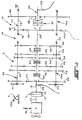
- Figure 1 is a schematic illustration of the vehicular mechanical transmission system partially automated by the system of the present invention.
- Figure 1A is a schematic illustration of the shift pattern of the transmission of Figure 1 .
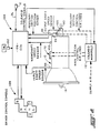
- Figure 2 is a schematic illustration of the automatic preselect and semi-automatic shift implementation system for a mechanical transmission system of the present invention.
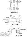
- Figure 3A is a schematic illustration of logic for differentiating signals representative of current vehicle and engine speed.
- Figure 3B is a schematic illustration of logic for calculating an expected vehicle acceleration during the shift transient when zero engine torque is applied to the drive wheels.
- FIGS 4A and 4B are schematic illustrations, in flow chart format, of the inventive control method of the present invention.
- Figure 5 is a graphical representation of an upshift event illustrating both feasible and not feasible attempted shifts.
- Figure 6 is a graphical representation, similar to Figure 5 , of engine speed and input shaft speed during an upshift.
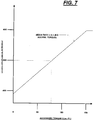
- Figure 7 is a graphical representation of the substantially linear relationship between accessory torque (T ACCES ) and engine deceleration rate (dES/dt rate).
- compound transmission is used to designate a change speed or change gear transmission having a multiple forward speed main transmission section and a multiple speed auxiliary transmission section connected in series whereby the selected gear reduction in the main transmission section may be compounded by further selected gear reduction in the auxiliary transmission section.
- "Synchronized clutch assembly” and words of similar import shall designate a clutch assembly utilized to nonrotatably couple a selected gear to a shaft by means of a positive clutch in which attempted engagement of said clutch is prevented until the members of the clutch are at substantially synchronous rotation.
- a relatively large capacity friction means are utilized with the clutch members and are sufficient, upon initiation of a clutch engagement, to cause the clutch members and all members rotating therewith to rotate at substantially synchronous speed.
- upshift shall mean the shifting from a lower speed gear ratio into a higher speed gear ratio.
- downshift shall mean the shifting from a higher speed gear ratio to a lower speed gear ratio.
- low speed gear shall all designate the gear ratio utilized for lowest forward speed operation in a transmission or transmission section, i.e. , that set of gears having the highest ratio of reduction relative to the input shaft of the transmission.
- Compound transmission 10 comprises a multiple speed main transmission section 12 connected in series with a range type auxiliary section 14.
- Transmission 10 is housed within a housing H and includes an input shaft 16 driven by a prime mover such as diesel engine E through a selectively disengaged, normally engaged friction master clutch C having an input or driving portion 18 drivingly connected to the engine crankshaft 20 and a driven portion 22 rotatably fixed to the transmission input shaft 16.
- a prime mover such as diesel engine E
- a selectively disengaged, normally engaged friction master clutch C having an input or driving portion 18 drivingly connected to the engine crankshaft 20 and a driven portion 22 rotatably fixed to the transmission input shaft 16.
- the engine E is fuel throttle controlled, preferably electronically, and is connected to an electronic data link DL of the type defined in SAE J 1922 or J 1939 protocol, and the master clutch C is manually controlled by a clutch pedal (not shown) or the like.
- the clutch C is utilized only for start-from-stop and for inching operation of the vehicle.
- control method/system of the present invention is particularly useful for those automated mechanical transmission systems not having automatic clutch actuators or input shaft brakes, the present invention is not limited to such use.
- the input shaft 16 carries an input gear 24 for simultaneously driving a plurality of substantially identical countershaft assemblies 26 and 26A at substantially identical rotational speeds.
- the two substantially identical countershaft assemblies are provided on diametrically opposite sides of mainshaft 28 which is generally coaxially aligned with the input shaft 16.
- Each of the countershaft assemblies comprises a countershaft 30 supported by bearings 32 and 34 in housing H, only a portion of which is schematically illustrated.
- Each of the countershafts is provided with an identical grouping of countershaft gears 38, 40, 42, 44, 46 and 48, fixed for rotation therewith.
- a plurality of mainshaft gears 50, 52, 54, 56 and 58 surround the mainshaft 28 and are selectively clutchable, one at a time, to the mainshaft 28 for rotation therewith by sliding clutch collars 60, 62 and 64 as is well known in the prior art.
- Clutch collar 60 may also be utilized to clutch input gear 24 to mainshaft 28 to provide a direct drive relationship between input shaft 16 and mainshaft 28.
- clutch collars 60, 62 and 64 are axially positioned by means of shift forks associated with the shift housing assembly 70, as well known in the prior art.
- Clutch collars 60, 62 and 64 may be of the well known nonsynchronized double acting jaw clutch type.
- Shift housing or actuator 70 is actuated by compressed fluid, such as compressed air, and is of the type automatically controllable by a control unit as may be seen by reference to U.S. Pats. No. 4,445,393; 4,555,959; 4,361,060; 4,722,237; 4,873,881; 4,928,544 and 2,931,237, the disclosures of which are incorporated by reference.
- Mainshaft gear 58 is the reverse gear and is in continuous meshing engagement with countershaft gears 48 by means of conventional intermediate idler gears (not shown). It should also be noted that while main transmission section 12 does provide five selectable forward speed ratios, the lowest forward speed ratio, namely that provided by drivingly connecting mainshaft drive gear 56 to mainshaft 28, is often of such a high gear reduction it has to be considered a low or "creeper" gear which is utilized only for starting of a vehicle under severe conditions and, is not usually utilized in the high transmission range. Accordingly, while main transmission section 12 does provide five forward speeds, it is usually referred to as a "four plus one" main section as only four of the forward speeds are compounded by the auxiliary range transmission section 14 utilized therewith.
- Jaw clutches 60, 62, and 64 are three-position clutches in that they may be positioned in the centered, nonengaged position as illustrated, or in a fully rightwardly engaged or fully leftwardly engaged position by means of actuator 70. As is well known, only one of the clutches 60, 62 and 64 is engageable at a given time and main section interlock means (not shown) are provided to lock the other clutches in the neutral condition.
- Auxiliary transmission range section 14 includes two substantially identical auxiliary countershaft assemblies 74 and 74A, each comprising an auxiliary countershaft 76 supported by bearings 78 and 80 in housing H and carrying two auxiliary section countershaft gears 82 and 84 for rotation therewith.
- Auxiliary countershaft gears 82 are constantly meshed with and support range/output gear 86 while auxiliary section countershaft gears 84 are constantly meshed with output gear 88.
- a two-position synchronized jaw clutch assembly 92 which is axially positioned by means of a shift fork (not shown) and the range section shifting actuator assembly 96, is provided for clutching either gear 86 to output shaft 90 for direct or high range operation or gear 88 to output shaft 90 for low range operation of the compound transmission 10.
- the "shift pattern" for compound range type transmission 10 is schematically illustrated in Figure 1A.
- Range section actuator 96 may be of the type illustrated in U.S. Pats. No. 3,648,546; 4,440,037 and 4,614,126, the disclosures of which are incorporated herein by reference.
- range-type auxiliary section 14 is illustrated as a two-speed section utilizing spur or helical type gearing, it is understood that the present invention is also applicable to range type transmissions utilizing combined splitter/range type auxiliary sections, having three or more selectable range ratios and/or utilizing planetary type gearing. Also, any one or more of clutches 60, 62 or 64 may be of the synchronized jaw clutch type and transmission sections 12 and/or 14 may be of the single countershaft type.
- an input shaft speed (IS) sensor and an output shaft speed (OS) sensor 100 are utilized.
- a sensor 102 for sensing the rotational speed of auxiliary section countershaft gear 82 may be utilized.
- the rotational speed of gear 82 is, of course, a known function of the rotational speed of mainshaft 28 and, if clutch 92 is engaged in a known position, a function of the rotational speed of output shaft 90. Further, with main clutch C fully engaged, input shaft speed (IS) will equal engine speed (ES).
- Control system 104 in addition to the mechanical transmission 10 described above, includes an electronic control unit 106, preferably microprocessor based, for receiving input signals from the input shaft speed sensor 98, from the output shaft speed sensor 100 (or, alternatively, the mainshaft speed sensor 102), from the driver control console 108, from a throttle pedal P position sensor 152, and from the engine E though data link DL.
- an electronic control unit 106 preferably microprocessor based, for receiving input signals from the input shaft speed sensor 98, from the output shaft speed sensor 100 (or, alternatively, the mainshaft speed sensor 102), from the driver control console 108, from a throttle pedal P position sensor 152, and from the engine E though data link DL.
- ES engine speed
- T EG gross engine torque
- T BEF base engine friction torque
- the ECU 106 may also receive inputs from an auxiliary section position sensor 110.
- the ECU 106 may be of the type schematically illustrated in U.S. Patent No. 4,595,986, the disclosure of which is incorporated herein by reference.
- the ECU is effective to process the inputs in accordance with predetermined logic rules to issue command output signals to a transmission operator, such as solenoid manifold 112 which controls the mainsection section actuator 70 and the auxiliary section actuator 96, and to the driver control console 108, and through the data link DL to engine E.
- a transmission operator such as solenoid manifold 112 which controls the mainsection section actuator 70 and the auxiliary section actuator 96, and to the driver control console 108, and through the data link DL to engine E.
- the driver control counsel allows the operator to manually select a shift in a given direction (up or down) or to neutral from the currently engaged ratio, or to select a semi-automatic preselect mode of operation (D), and preferably provides a display for informing the operator of the current mode of operation (automatic or manual preselection of shifting), the current transmission operation condition (forward, reverse or neutral) and of any ratio change or shift (upshift, downshift or shift to neutral) which has been preselected but not yet implemented .
- Console 108 may be of the "R-N-D-H-L" (i.e. , reverse-neutral-drive-hold-low) type with a manual upshift and downshift selector.
- the manifold 112 is preselected to cause actuator 70 to be biased to shift main transmission section 12 into neutral. This is accomplished by the operator or the ECU controller causing a torque reversal by momentarily decreasing and/or increasing the supply of fuel to the engine, see U.S. Pat. No. 4,850,236, the disclosure of which is incorporated herein by reference.
- the ECU neutral sensed for a period of time such as 1.5 seconds
- a shift of both the main section 12 and of the range section 14, such as a shift from fourth to fifth speeds as seen in Figure 1A the ECU will issue command output signals to manifold 112 to cause the auxiliary section actuator 96 to complete the range shift after neutral is sensed in the front box.
- the ECU When the range auxiliary section is engaged in the proper ratio, the ECU will calculate or otherwise determine, and continue to update, an enabling range or band of input shaft speeds, based upon sensed output shaft (vehicle) speed and the ratio to be engaged (GR TARGET ), which will result in an acceptably synchronous engagement of the ratio to be engaged.
- the ECU As the operator or the ECU, by throttle manipulation, causes the input shaft speed to fall within the acceptable range, the ECU 106 will issue command output signals to manifold 112 to cause actuator 70 to engage the mainsection ratio to be engaged.
- an automatically or manually selected shift may not be completable or will result in unacceptable vehicle performance after completion of an upshift.
- These conditions usually involve upshifts when the vehicle is heavy loaded and/or is traveling against a great resistance, such as in mud, up a steep grade and/or into a strong headwind.
- the speed of the input shaft 10 (which substantially equals the speed of the engine E with the master clutch engaged) must be decreased to substantially equal the speed of the output shaft 90 (directly proportional to vehicle speed) multiplied by the target gear ratio.
- the speed of the input shaft will decrease with the rate of decay of engine speed.
- IS should substantially equal OS*GR TARGET and, with the master clutch fully engaged, IS will substantially equal ES.
- GR current gear ratio
- the expected speed of the output shaft 90 during the shift transient when zero engine torque is applied to the vehicle drive wheels (OS EXPECTED ) multiplied by the target gear ratio, which product is the required synchronous speed of the input shaft/engine, is represented by lines 208 and 210 illustrating, respectively, that product at a lesser or greater resistance to motion of the vehicle.
- lines 208 and 210 illustrating, respectively, that product at a lesser or greater resistance to motion of the vehicle.
- the engine/input shaft decay rate is about 300 to 800 RPM and both the engine and vehicle deceleration may be approximated as linear.
- the specific rate of decay of the engine and/or input shaft may be learned by differentiating the value of ES and/or IS signals during a defueling condition (see, for example, aforementioned U.S. Pat. No. 4,361,060).
- the decay rate may vary considerably, however, with temperature and use of engine-driven accessories.
- the input shaft speed (IS) (as determined by initial input shaft speed at point 202 and the acceleration of the input shaft (dlS/dt)) will be substantially equal to the product of expected output shaft speed at zero torque to the vehicle drive wheels (OS EXPECTED ), which is determined by initial OS (-IS/GR) and the vehicle acceleration (dOS/dt) at current resistance to vehicle motion, multiplied by the numerical value of the target gear ratio (GR TARGET ) at a value greater than a reference (such as engine idle speed 206), then achieving a synchronous shift into the selected target gear ratio is feasible; if not, achieving a substantially synchronous shift into the selected target gear ratio is infeasible.
- the OS and dOS/dt signals are, of course, equivalent to vehicle speed and vehicle acceleration signals, respectively.
- the reference value is illustrated as engine idle speed 206 but can be a lower positive value if the master clutch is manually or automatically disengaged.
- GCW gross combined weight
- the controller will determine current GCW. From this information, the system can determine what the vehicle acceleration (usually a deceleration) will be at zero driveline torque, i.e. , the slope of line 208 or 210. Based upon this information and a present or learned value of engine decay rate, i.e. , the slope of line 204, which may vary with engine speed, operating temperature, operation of an engine brake, etc., the ECU can then determine if, under current vehicle operating conditions, the system is able to successfully complete the proposed upshift.
- GCW gross combined weight
- control system can then either (i) issue command signals to implement the proposed upshift, or (ii) modify the proposed shift (usually command a single rather than a skip upshift, or (iii) cancel/prohibit the shift request for a predetermined period of time (such as, for example, about 10 seconds).
- a O TORQUE A i - (T i /CW)
- Figure 3A schematically illustrates a logic element or subroutine 220 for differentiating various input signals 222, such as OS and/or ES, to determine the derivatives with respect to time thereof, dOS/dt and/or dES/dt, as output signals 224.
- input signals 222 such as OS and/or ES
- Figure 3B schematically illustrates a logic element or subroutine 226 wherein input signals 228, including signals indicative of engine torque and vehicle acceleration (dOS/dt), are processed according to the logic rules set forth above to determine an output signal value 230 indicative of expected vehicle acceleration (dOS/dt) during the shift transient when no engine torque is applied to the vehicle drive wheels.
- input signals 228, including signals indicative of engine torque and vehicle acceleration (dOS/dt) are processed according to the logic rules set forth above to determine an output signal value 230 indicative of expected vehicle acceleration (dOS/dt) during the shift transient when no engine torque is applied to the vehicle drive wheels.
- flywheel torque is a function of accessory torque.
- the control of this invention uses torque information from the engine (preferably an electronic engine) along with vehicle and engine acceleration information to calculate these control parameters.
- Drivewheel torque may be determined as a function of engine flywheel torque (i.e. , input torque to the vehicle master clutch or torque converter) if drivetrain parameters, such as current transmission gear ratio, drive axle ratio, drivetrain efficiency and tire size, are known.
- T EG Gross engine torque
- T BEF base engine friction torque
- T ACCEL Torque to accelerate the engine
- T FW flywheel torque
- T ACCES accessory torque
- the value of accessory torque (T ACCES ) may vary substantially and often, as vehicular accessories such as lights, air-conditioning, fan drives and the like are turned off and on automatically or by the vehicle operator and/or passengers.
- T ACCES engine accessory torque
- dES/dt rate engine deceleration rate
- dES/dt rate is the rate of engine deceleration when the transmission is in neutral and/or the master clutch is fully disengaged, and fueling is set at a minimal value.
- dES/dt rate is the rate of engine deceleration when the transmission is in neutral and/or the master clutch is fully disengaged, and fueling is set at a minimal value.
- the engine deceleration rate increases in proportion to it.
- dES/dt engine deceleration rate
- Engine deceleration when the vehicle is in motion and upshifting is determined as follows.
- the engine is operated in a "predip" mode prior to disengagement of the existing ratio, in a "synchronizing” mode after a shift from the existing ratio into neutral, and in the "throttle recovery” mode immediately after engagement of the target gear ratio.
- the engine and input shaft speeds in these modes are illustrated in Figure 6 .
- fueling is modulated to cause driveline torque reversals to relieve torque lock conditions.
- readings must be taken during the synchronous engine control phase of an upshift, and should include a first reading at or near point A in Figure 6 when the synchronous engine control phase is first initiated, and a second reading at or near point B in Figure 6 when the synchronous engine control phase is ended or is about to end.
- the occurrence of point A is taken as the first time operation in the synchronous mode is sensed.
- the occurrence of point B is taken as the first time operation in the throttle recovery mode is sensed.
- a 4:1 to 20:1 filtering technique preferably about a 7:1 filtering technique, provides suitable responsiveness while filtering out the drivetrain noises due to vibrations, torsionals and the like.
- the present invention provides a control method/system for controlling an at least partially automated vehicular mechanical transmission system wherein accessory torque and engine deceleration rate may be determined with the vehicle in motion or at rest.
- accessory torque is substantially equal to gross engine torque minus base engine friction torque (T EG - T BEF ).
- T EG - T BEF is also referred to as "net engine torque.” This value is preferably sensed from the databus or datalink (DL) and preferably subject to a filtering averaging process.
- the system controller is provided with information which relates engine deceleration rate (dES/dt rate) to accessory torque (T ACCES ) in a predetermined, substantially linear manner wherein engine deceleration rate equals A + (B * accessory torque) where "A" and "B" are predetermined, stored parameters. If dES/dt rate is in units of RPM/second and T ACCES is in units of pound-feet, then "A” will be in units of RPM/second and "B” will be in units of RPM/second/pound-feet.
- Figure 7 is a graphical representation of this relationship.
- an expected engine deceleration rate may be determined while the vehicle is at rest.
- the rate thus determined or derived is an approximation for the system logic to utilize for vehicle start-up and is corrected and updated using filtered, actually sensed engine deceleration values as soon as the vehicle gets moving and making upshifts.
- engine deceleration rate equals -385 + (-2 * T ACCEL ) and, at an observed, averaged engine deceleration rate (dES/dt rate) of -500 RPM/second, accessory torque (T ACCES ) would equal about 81.25 pound feet.
- linear relationship is defined as predetermined for a given vehicle configuration, the relationship also may be adatively learned by the controller logic or empirically determined at the end of the vehicle assembly line. For example, to determine this substantially linear relationship during the end of the vehicle assembly line checkout and testing procedure, the following procedure may be followed:
- T FW T EG - T BEF - T ACCES - T ACCEL and of engine deceleration rate (dES/dt rate) may be determined.
- the accessory torque (T ACCES ), flywheel torque (T FW ) and engine deceleration rate (dES/dt rate) determination method/system of the present invention is schematically illustrated, in flow chart format, in Figures 4A and 4B .
- a relatively simple and inexpensive shift implementation control system/method for automated mechanical transmission system 10 which utilizes existing input signals and a determined relationship between unaided engine deceleration rate (dES/dt rate) and accessory torque (T ACCES ) to provide accurate values indicative of the accessory torque (T ACCES ), flywheel torque (T FW ) and engine deceleration rate (dES/dt rate) control parameters.
- dES/dt rate unaided engine deceleration rate
- T ACCES accessory torque
- T FW flywheel torque
- dES/dt rate engine deceleration rate
Applications Claiming Priority (2)
| Application Number | Priority Date | Filing Date | Title |
|---|---|---|---|
| US08/242,824 US5582069A (en) | 1994-05-16 | 1994-05-16 | Engine accessory torque and engine deceleration rate determination method/system |
| US242824 | 1994-05-16 |
Publications (2)
| Publication Number | Publication Date |
|---|---|
| EP0683336A1 true EP0683336A1 (de) | 1995-11-22 |
| EP0683336B1 EP0683336B1 (de) | 1998-01-14 |
Family
ID=22916328
Family Applications (1)
| Application Number | Title | Priority Date | Filing Date |
|---|---|---|---|
| EP95302963A Expired - Lifetime EP0683336B1 (de) | 1994-05-16 | 1995-05-01 | Vorrichtung/Verfahren zur Erstellung des Antriebsdrehmoments der Motorzusatzvorrichtungen und Verzögerungsgeschwindigkeit dieses Moments |
Country Status (10)
| Country | Link |
|---|---|
| US (2) | US5582069A (de) |
| EP (1) | EP0683336B1 (de) |
| JP (1) | JPH0811590A (de) |
| KR (1) | KR100237839B1 (de) |
| CN (1) | CN1101013C (de) |
| AT (1) | ATE162281T1 (de) |
| BR (1) | BR9502095A (de) |
| CA (1) | CA2148163C (de) |
| DE (1) | DE69501427T2 (de) |
| ES (1) | ES2112610T3 (de) |
Cited By (9)
| Publication number | Priority date | Publication date | Assignee | Title |
|---|---|---|---|---|
| WO1997004979A1 (en) * | 1995-07-27 | 1997-02-13 | Rockwell International Corporation | Method and apparatus for assisting in shifting transmission to neutral |
| WO1997004983A2 (en) * | 1995-07-27 | 1997-02-13 | Rockwell International Corporation | Input switch and engine control method for manual gear shifting |
| EP0787619A3 (de) * | 1996-02-07 | 1998-12-16 | Scania Cv Aktiebolag | Verfahren zur Korrektur des Brennkraftmaschinen-Drehmoments bei Schaltvorgängen eines Getriebes |
| EP1085305A2 (de) * | 1999-09-16 | 2001-03-21 | Eaton Corporation | Verfahren/Einrichtung zur Rücksetzung des Wertes eines Steuerparameters, die das Kombinationsgesamtgewicht eines Fahrzeugs gegenüber einem Standartwert dafür anzeigt |
| EP1148273A1 (de) * | 2000-04-18 | 2001-10-24 | Ford Global Technologies, Inc. | Drehmoment Schätzungsverfahren für Verbrennungsmotor und dessen Nebenaggregaten |
| GB2389878A (en) * | 2002-06-18 | 2003-12-24 | Eaton Corp | Method of detecting false neutral in a transmission system |
| EP1216877A3 (de) * | 2000-12-21 | 2005-07-27 | Eaton Corporation | Brennkraftmaschinensteuerung zur Erzeugung eines abnehmenden Antriebsmoments |
| WO2013020761A1 (de) * | 2011-08-11 | 2013-02-14 | Zf Friedrichshafen Ag | Verfahren zur schaltsteuerung eines automatisierten gruppengetriebes |
| WO2019214890A1 (de) * | 2018-05-08 | 2019-11-14 | Zf Friedrichshafen Ag | Drehmomentermittlung bei nebenverbrauchern |
Families Citing this family (50)
| Publication number | Priority date | Publication date | Assignee | Title |
|---|---|---|---|---|
| DE19709417A1 (de) * | 1996-03-14 | 1997-10-30 | Luk Getriebe Systeme Gmbh | Vorrichtung zur Ansteuerung eines Drehmomentübertragungssystems und eines Getriebes, sowie ein Verfahren hierfür |
| US5720696A (en) * | 1996-04-25 | 1998-02-24 | General Motors Corporation | Method of shift control using moment of inertia estimation |
| US6792344B2 (en) * | 1997-04-25 | 2004-09-14 | Hitachi, Ltd. | Automotive control apparatus and method |
| US6052638A (en) | 1998-02-20 | 2000-04-18 | Eaton Corporation | Engine flywheel torque control |
| US6042504A (en) | 1998-04-01 | 2000-03-28 | Eaton Corporation | Range shift control |
| US5989155A (en) | 1998-04-01 | 1999-11-23 | Eaton Corporation | Engine fuel control for completing shifts in controller-assisted, manually shifted transmission |
| US5984831A (en) | 1998-04-01 | 1999-11-16 | Eaton Corporation | Adaptive upshift jaw clutch engagement control |
| US5911787A (en) | 1998-04-01 | 1999-06-15 | Eaton Corporation | Dynamic range shift actuation |
| IT1301760B1 (it) * | 1998-06-19 | 2000-07-07 | Ducati Energia Spa | Metodo e dispositivo per il controllo del minimo motore |
| US6113516A (en) * | 1999-01-14 | 2000-09-05 | Eaton Corporation | Adaptive automated transmission upshift control |
| US6325743B1 (en) | 1999-01-14 | 2001-12-04 | Eaton Corporation | Automated transmission upshift control |
| US6149545A (en) * | 1999-01-14 | 2000-11-21 | Eaton Corporation | Automated transmission upshift control |
| US6146310A (en) * | 1999-01-15 | 2000-11-14 | Eaton Corporation | Adaptive automated transmission downshift control |
| US6066071A (en) * | 1999-01-15 | 2000-05-23 | Eaton Corporation | Automated transmission downshift control |
| JP3624741B2 (ja) * | 1999-05-17 | 2005-03-02 | 三菱自動車工業株式会社 | 無段変速機の制御装置 |
| US6126569A (en) * | 1999-07-19 | 2000-10-03 | Eaton Corporation | Starting and driveline shock protection control method and system |
| US6123644A (en) * | 1999-07-19 | 2000-09-26 | Eaton Corporation | Adaptive anti-hunt logic for automated transmission downshift control |
| US6409629B1 (en) | 2000-05-17 | 2002-06-25 | Eaton Corporation | Automated transmission upshift control with upshift brake thermal protection |
| US6491603B1 (en) | 2000-09-12 | 2002-12-10 | Eaton Corporation | Automated transmission shift control |
| US6502476B2 (en) | 2000-12-13 | 2003-01-07 | Eaton Corporation | Transmission system utilizing centrifugal clutch |
| US6526816B2 (en) * | 2000-12-13 | 2003-03-04 | Eaton Corporation | Transmission gear life monitor system |
| GB2371839A (en) * | 2001-02-01 | 2002-08-07 | Eaton Corp | Control for selecting automated transmission system shift strategy |
| US6539820B2 (en) | 2001-03-21 | 2003-04-01 | Eaton Corporation | Method and system for transmission utilizing centrifugal clutch to overcome transmission tooth-butt |
| US6641504B2 (en) | 2001-03-21 | 2003-11-04 | Eaton Corporation | Method and system for establishing an engine speed target for use by a centrifugal clutch control system to launch a vehicle |
| US6461273B1 (en) | 2001-06-01 | 2002-10-08 | Eaton Corporation | Automated transmission upshift brake control |
| US6633806B2 (en) | 2001-08-30 | 2003-10-14 | Eaton Corporation | Control for transmission system utilizing a centrifugal clutch |
| DE10330517A1 (de) * | 2003-07-05 | 2005-03-03 | Zf Friedrichshafen Ag | Verfahren zur Steuerung und Regelung einer Getriebebremse in einem Kraftfahrzeug-Automatgetriebe |
| US7480555B2 (en) | 2004-12-16 | 2009-01-20 | Eaton Corporation | Method for controlling centrifugal clutch engagement using engine torque requests |
| US20080194383A1 (en) * | 2005-09-08 | 2008-08-14 | Volvo Lastvagnar Ab | Method for Adapting an Automated Mechanical Transmission Based on a Measured Pto Load |
| DE602006018631D1 (de) * | 2005-09-08 | 2011-01-13 | Volvo Lastvagnar Ab | Verfahren und anordnung zum anpassen von gangwechselstrategien in schwerlastfahrzeugen mit einem automatikgetriebe unter zapfwellenlast |
| JP2007315472A (ja) * | 2006-05-25 | 2007-12-06 | Iseki & Co Ltd | トラクターの走行装置 |
| US7324888B1 (en) * | 2006-10-02 | 2008-01-29 | Ford Global Technologies, Llc | Computationally efficient data-driven algorithms for engine friction torque estimation |
| US7905812B2 (en) * | 2007-02-02 | 2011-03-15 | Eaton Corporation | PTO brake |
| US8046140B2 (en) | 2008-01-18 | 2011-10-25 | Eaton Corporation | PTO overspeed protection strategy |
| DE102008040126A1 (de) * | 2008-07-03 | 2010-01-07 | Zf Friedrichshafen Ag | Verfahren zum Ansteuern eines Schaltvorganges bei einem automatischen Getriebe eines Nutzfahrzeuges |
| DE102011075913A1 (de) | 2011-05-16 | 2012-11-22 | Zf Friedrichshafen Ag | Verfahren zum Bestimmen eines Schaltablaufes eines Übersetzungswechsels einer Getriebeeinrichtung eines Fahrzeugantriebsstranges |
| US8948977B2 (en) * | 2011-12-28 | 2015-02-03 | Caterpillar Inc. | Systems and methods for machine implement control |
| DE102012208881A1 (de) * | 2012-05-25 | 2013-11-28 | Robert Bosch Gmbh | Verfahren und Vorrichtung zum Adaptieren eines Verlustdrehmoments eines Verbrennungsmotors |
| JP6261347B2 (ja) * | 2013-03-12 | 2018-01-17 | 泰三 嶋田 | エンジンの摩擦損失測定方法およびエンジンの駆動状態検出方法 |
| US9267480B1 (en) * | 2013-05-10 | 2016-02-23 | The Boeing Company | Electrical power generating engine flywheel with active torque control |
| KR101484215B1 (ko) * | 2013-06-19 | 2015-01-16 | 현대자동차 주식회사 | 하이브리드 차량의 시동모터 고장시 엔진 시동 방법 및 시스템 |
| CN103697154B (zh) * | 2013-11-29 | 2016-04-27 | 浙江吉利控股集团有限公司 | 一种amt自动变速器的换挡方法 |
| RU2550585C1 (ru) * | 2014-01-17 | 2015-05-10 | Открытое акционерное общество "АВИАЦИОННЫЕ РЕДУКТОРА И ТРАНСМИССИИ - ПЕРМСКИЕ МОТОРЫ" (ОАО "Редуктор-ПМ") | Механизм загрузки крутящим моментом |
| JP2016057114A (ja) * | 2014-09-08 | 2016-04-21 | 泰三 嶋田 | エンジンの慣性モーメント測定方法およびエンジンの摩擦損失測定方法 |
| DE102016211950A1 (de) * | 2016-06-30 | 2018-01-04 | Zf Friedrichshafen Ag | Verfahren zur Übertragung und Dämpfung von Drehmomenten |
| CN111376892B (zh) * | 2018-12-29 | 2022-07-15 | 河南森源重工有限公司 | 一种车辆、车辆转毂测试控制方法及装置 |
| DE102019216211A1 (de) * | 2019-10-22 | 2021-04-22 | Zf Friedrichshafen Ag | Verfahren und Steuergerät zum Betreiben eines Antriebsstrangs eines Kraftfahrzeugs mit einem Nebenabtrieb |
| CN113819234A (zh) * | 2021-08-18 | 2021-12-21 | 潍柴动力股份有限公司 | 一种换挡辅助控制方法、车辆 |
| DE102022200607A1 (de) | 2022-01-20 | 2023-07-20 | Zf Friedrichshafen Ag | Kraftfahrzeuggetriebe, insbesondere Elektrofahrzeuggetriebe |
| DE102022200615A1 (de) | 2022-01-20 | 2023-07-20 | Zf Friedrichshafen Ag | Kraftfahrzeuggetriebe, insbesondere Elektrofahrzeuggetriebe |
Citations (5)
| Publication number | Priority date | Publication date | Assignee | Title |
|---|---|---|---|---|
| DE4304779A1 (de) * | 1992-06-20 | 1993-12-23 | Bosch Gmbh Robert | Vorrichtung zur Steuerung des von einer Antriebseinheit eines Fahrzeugs abzugebenden Drehmoments |
| US5272939A (en) * | 1992-07-06 | 1993-12-28 | Eaton Corporation | Shift enable control method/system |
| EP0578398A2 (de) * | 1992-07-06 | 1994-01-12 | Eaton Corporation | Verfahren und Vorrichtung zur Gangschaltsteuerung |
| EP0616919A2 (de) * | 1993-03-26 | 1994-09-28 | Hitachi, Ltd. | Vorrichtung zur Regelung der Antriebskraft im Antriebsstrang eines Kraftfahrzeuges |
| US5425689A (en) * | 1992-07-06 | 1995-06-20 | Eaton Corporation | Engine brake enhanced upshift control method/system |
Family Cites Families (18)
| Publication number | Priority date | Publication date | Assignee | Title |
|---|---|---|---|---|
| US3942365A (en) * | 1975-04-21 | 1976-03-09 | Rca Corporation | Power test means and method for internal combustion engines |
| US4361060A (en) * | 1978-01-24 | 1982-11-30 | Smyth Robert Ralston | Mechanical automatic transmission |
| DE3122362A1 (de) * | 1981-06-05 | 1983-01-05 | Xaver Fendt & Co, 8952 Marktoberdorf | Verfahren zur bestimmung der momentanleistung eines antriebsmotors |
| JPS59120748A (ja) * | 1982-12-27 | 1984-07-12 | Nissan Motor Co Ltd | エンジンの発生トルク推定装置 |
| DE3416496A1 (de) * | 1984-05-04 | 1985-11-07 | Brown, Boveri & Cie Ag, 6800 Mannheim | Verfahren und schaltungsanordnung zum simulieren von pruefstandstraegheitsmomenten |
| GB8418749D0 (en) * | 1984-07-23 | 1984-08-30 | Eaton Ltd | Semi-automatic transmission control |
| US4595986A (en) * | 1984-10-09 | 1986-06-17 | Eaton Corporation | Method for control of automatic mechanical transmission system utilizing a microprocessor based electronic controller |
| US5231582A (en) * | 1989-03-29 | 1993-07-27 | Nissan Motor Company | Shifting control system for automotive automatic power transmission with enhanced variable shift pattern selection depending upon a resistance based upon vehicle acceleration and an engine parameter |
| US5053959A (en) * | 1989-06-19 | 1991-10-01 | Eaton Corporation | Control system and method for sensing and indicating neutral in a semi-automatic mechanical transmission system |
| US5053961A (en) * | 1989-06-19 | 1991-10-01 | Eaton Corporation | Semi-automatic shift implementation for mechanical transmission system |
| US5053962A (en) * | 1989-06-19 | 1991-10-01 | Eaton Corporation | Automatic shift preselection mode for mechanical transmission system with semi-automatic shift implementation |
| US5089965A (en) * | 1989-07-24 | 1992-02-18 | Eaton Corporation | Shift prohibiting for automatic shift preselection mode for mechanical transmission system with semi-automatic shift implementation |
| JP2827396B2 (ja) * | 1990-02-16 | 1998-11-25 | トヨタ自動車株式会社 | 車両用自動変速機 |
| KR940009849B1 (ko) * | 1990-04-17 | 1994-10-18 | 미쓰비시덴키가부시키가이샤 | 자동변속기 제어장치 |
| US5241476A (en) * | 1990-05-08 | 1993-08-31 | Chrysler Corporation | Acceleration prediction responsive adaptive upshift control |
| JPH0494439A (ja) * | 1990-08-09 | 1992-03-26 | Japan Electron Control Syst Co Ltd | 内燃機関の出力表示装置 |
| KR100289507B1 (ko) * | 1991-12-03 | 2001-06-01 | 가나이 쓰도무 | 자동차의 자동변속제어장치 및 제어방법 |
| US5172609A (en) * | 1992-03-02 | 1992-12-22 | Saturn Corporation | Gradeability-based shift pattern control for an automatic transmission |
-
1994
- 1994-05-16 US US08/242,824 patent/US5582069A/en not_active Expired - Lifetime
- 1994-09-21 US US08/309,713 patent/US5620392A/en not_active Expired - Lifetime
-
1995
- 1995-04-28 CA CA002148163A patent/CA2148163C/en not_active Expired - Fee Related
- 1995-05-01 AT AT95302963T patent/ATE162281T1/de not_active IP Right Cessation
- 1995-05-01 EP EP95302963A patent/EP0683336B1/de not_active Expired - Lifetime
- 1995-05-01 DE DE69501427T patent/DE69501427T2/de not_active Expired - Fee Related
- 1995-05-01 ES ES95302963T patent/ES2112610T3/es not_active Expired - Lifetime
- 1995-05-12 KR KR1019950011671A patent/KR100237839B1/ko not_active IP Right Cessation
- 1995-05-15 BR BR9502095A patent/BR9502095A/pt not_active IP Right Cessation
- 1995-05-16 JP JP7141136A patent/JPH0811590A/ja active Pending
- 1995-05-16 CN CN95106048A patent/CN1101013C/zh not_active Expired - Fee Related
Patent Citations (7)
| Publication number | Priority date | Publication date | Assignee | Title |
|---|---|---|---|---|
| DE4304779A1 (de) * | 1992-06-20 | 1993-12-23 | Bosch Gmbh Robert | Vorrichtung zur Steuerung des von einer Antriebseinheit eines Fahrzeugs abzugebenden Drehmoments |
| US5272939A (en) * | 1992-07-06 | 1993-12-28 | Eaton Corporation | Shift enable control method/system |
| EP0578398A2 (de) * | 1992-07-06 | 1994-01-12 | Eaton Corporation | Verfahren und Vorrichtung zur Gangschaltsteuerung |
| EP0578399A2 (de) * | 1992-07-06 | 1994-01-12 | Eaton Corporation | Verfahren und Vorrichtung zur Freigabe eines Gangwechsels |
| US5272939B1 (en) * | 1992-07-06 | 1994-12-06 | Eaton Corp | Shift enable control method/system |
| US5425689A (en) * | 1992-07-06 | 1995-06-20 | Eaton Corporation | Engine brake enhanced upshift control method/system |
| EP0616919A2 (de) * | 1993-03-26 | 1994-09-28 | Hitachi, Ltd. | Vorrichtung zur Regelung der Antriebskraft im Antriebsstrang eines Kraftfahrzeuges |
Cited By (15)
| Publication number | Priority date | Publication date | Assignee | Title |
|---|---|---|---|---|
| WO1997004983A2 (en) * | 1995-07-27 | 1997-02-13 | Rockwell International Corporation | Input switch and engine control method for manual gear shifting |
| WO1997004983A3 (en) * | 1995-07-27 | 1997-05-09 | Rockwell International Corp | Input switch and engine control method for manual gear shifting |
| AU719274B2 (en) * | 1995-07-27 | 2000-05-04 | Detroit Diesel Corporation | Method and apparatus for assisting in shifting transmission to neutral |
| WO1997004979A1 (en) * | 1995-07-27 | 1997-02-13 | Rockwell International Corporation | Method and apparatus for assisting in shifting transmission to neutral |
| EP0787619A3 (de) * | 1996-02-07 | 1998-12-16 | Scania Cv Aktiebolag | Verfahren zur Korrektur des Brennkraftmaschinen-Drehmoments bei Schaltvorgängen eines Getriebes |
| EP1085305A3 (de) * | 1999-09-16 | 2002-01-30 | Eaton Corporation | Verfahren/Einrichtung zur Rücksetzung des Wertes eines Steuerparameters, die das Kombinationsgesamtgewicht eines Fahrzeugs gegenüber einem Standartwert dafür anzeigt |
| EP1085305A2 (de) * | 1999-09-16 | 2001-03-21 | Eaton Corporation | Verfahren/Einrichtung zur Rücksetzung des Wertes eines Steuerparameters, die das Kombinationsgesamtgewicht eines Fahrzeugs gegenüber einem Standartwert dafür anzeigt |
| EP1148273A1 (de) * | 2000-04-18 | 2001-10-24 | Ford Global Technologies, Inc. | Drehmoment Schätzungsverfahren für Verbrennungsmotor und dessen Nebenaggregaten |
| EP1216877A3 (de) * | 2000-12-21 | 2005-07-27 | Eaton Corporation | Brennkraftmaschinensteuerung zur Erzeugung eines abnehmenden Antriebsmoments |
| GB2389878A (en) * | 2002-06-18 | 2003-12-24 | Eaton Corp | Method of detecting false neutral in a transmission system |
| WO2013020761A1 (de) * | 2011-08-11 | 2013-02-14 | Zf Friedrichshafen Ag | Verfahren zur schaltsteuerung eines automatisierten gruppengetriebes |
| US8870712B2 (en) | 2011-08-11 | 2014-10-28 | Zf Friedrichshafen Ag | Method for shift control of an automated group gear |
| WO2019214890A1 (de) * | 2018-05-08 | 2019-11-14 | Zf Friedrichshafen Ag | Drehmomentermittlung bei nebenverbrauchern |
| CN112088264A (zh) * | 2018-05-08 | 2020-12-15 | 采埃孚股份公司 | 在附加消耗器中确定转矩 |
| US11378180B2 (en) | 2018-05-08 | 2022-07-05 | Zf Friedrichshafen Ag | Torque determination in auxiliary consumers |
Also Published As
| Publication number | Publication date |
|---|---|
| ES2112610T3 (es) | 1998-04-01 |
| DE69501427D1 (de) | 1998-02-19 |
| KR950033019A (ko) | 1995-12-22 |
| US5582069A (en) | 1996-12-10 |
| BR9502095A (pt) | 1996-01-09 |
| JPH0811590A (ja) | 1996-01-16 |
| CA2148163C (en) | 2000-05-30 |
| ATE162281T1 (de) | 1998-01-15 |
| EP0683336B1 (de) | 1998-01-14 |
| CN1101013C (zh) | 2003-02-05 |
| US5620392A (en) | 1997-04-15 |
| CA2148163A1 (en) | 1995-11-17 |
| DE69501427T2 (de) | 1998-09-03 |
| KR100237839B1 (ko) | 2000-01-15 |
| CN1125859A (zh) | 1996-07-03 |
Similar Documents
| Publication | Publication Date | Title |
|---|---|---|
| EP0683336B1 (de) | Vorrichtung/Verfahren zur Erstellung des Antriebsdrehmoments der Motorzusatzvorrichtungen und Verzögerungsgeschwindigkeit dieses Moments | |
| US5509867A (en) | Engine flywheel torque determination method/system | |
| EP0676566B1 (de) | Verfahren und System zur Bestimmung einer Motorverzögerung | |
| EP0677684B1 (de) | Adaptive Verfahren und Vorrichtung für Gangschaltung | |
| EP0670440B1 (de) | Steuerverfahren und -vorrichtung zum Hochschalten mit Motorbremsenunterstützung | |
| CA2099552C (en) | Shift control method/system | |
| US5490063A (en) | Control method/system including determination of an updated value indicative of gross combination weight of vehicles | |
| EP0578399B1 (de) | Verfahren und Vorrichtung zur Freigabe eines Gangwechsels | |
| EP0695930B1 (de) | Bestimmung des Gesamtgewichts eines Fahrzeugs mit elektronischen Datenverbindungen | |
| US5761628A (en) | Start gear ratio control system and method utilizing the highest allowable start gear ratio | |
| US5592851A (en) | Semi-automatic mechanical transmission with forced automatic shifting | |
| US6500093B2 (en) | Automated transmission system control with zero engine flywheel torque determination | |
| EP0896172A2 (de) | Teilautomatisiertes, handgeschaltetes Getriebe | |
| US5441464A (en) | Non-power downshift throttle recovery | |
| EP0602849B1 (de) | Verfahren zur Fehlerbeseitigung bei erfolglosen Schaltversuchen aus dem Leerlauf in automatischen oder halbautomatischen mechanischen Getriebesystemen | |
| EP0937602B1 (de) | Steuerung des Motorschwungraddrehmoments |
Legal Events
| Date | Code | Title | Description |
|---|---|---|---|
| PUAI | Public reference made under article 153(3) epc to a published international application that has entered the european phase |
Free format text: ORIGINAL CODE: 0009012 |
|
| AK | Designated contracting states |
Kind code of ref document: A1 Designated state(s): AT DE ES FR GB IT NL SE |
|
| 17P | Request for examination filed |
Effective date: 19960425 |
|
| 17Q | First examination report despatched |
Effective date: 19960523 |
|
| GRAG | Despatch of communication of intention to grant |
Free format text: ORIGINAL CODE: EPIDOS AGRA |
|
| GRAG | Despatch of communication of intention to grant |
Free format text: ORIGINAL CODE: EPIDOS AGRA |
|
| GRAH | Despatch of communication of intention to grant a patent |
Free format text: ORIGINAL CODE: EPIDOS IGRA |
|
| GRAH | Despatch of communication of intention to grant a patent |
Free format text: ORIGINAL CODE: EPIDOS IGRA |
|
| GRAA | (expected) grant |
Free format text: ORIGINAL CODE: 0009210 |
|
| ITF | It: translation for a ep patent filed |
Owner name: STUDIO GLP S.R.L. |
|
| AK | Designated contracting states |
Kind code of ref document: B1 Designated state(s): AT DE ES FR GB IT NL SE |
|
| REF | Corresponds to: |
Ref document number: 162281 Country of ref document: AT Date of ref document: 19980115 Kind code of ref document: T |
|
| REF | Corresponds to: |
Ref document number: 69501427 Country of ref document: DE Date of ref document: 19980219 |
|
| REG | Reference to a national code |
Ref country code: ES Ref legal event code: FG2A Ref document number: 2112610 Country of ref document: ES Kind code of ref document: T3 |
|
| ET | Fr: translation filed | ||
| PLBE | No opposition filed within time limit |
Free format text: ORIGINAL CODE: 0009261 |
|
| STAA | Information on the status of an ep patent application or granted ep patent |
Free format text: STATUS: NO OPPOSITION FILED WITHIN TIME LIMIT |
|
| NLT2 | Nl: modifications (of names), taken from the european patent patent bulletin |
Owner name: EATON CORPORATION |
|
| 26N | No opposition filed | ||
| REG | Reference to a national code |
Ref country code: GB Ref legal event code: IF02 |
|
| PGFP | Annual fee paid to national office [announced via postgrant information from national office to epo] |
Ref country code: AT Payment date: 20050406 Year of fee payment: 11 |
|
| PGFP | Annual fee paid to national office [announced via postgrant information from national office to epo] |
Ref country code: NL Payment date: 20050407 Year of fee payment: 11 |
|
| PGFP | Annual fee paid to national office [announced via postgrant information from national office to epo] |
Ref country code: FR Payment date: 20050517 Year of fee payment: 11 |
|
| PGFP | Annual fee paid to national office [announced via postgrant information from national office to epo] |
Ref country code: ES Payment date: 20050520 Year of fee payment: 11 |
|
| PG25 | Lapsed in a contracting state [announced via postgrant information from national office to epo] |
Ref country code: AT Free format text: LAPSE BECAUSE OF NON-PAYMENT OF DUE FEES Effective date: 20060501 |
|
| PG25 | Lapsed in a contracting state [announced via postgrant information from national office to epo] |
Ref country code: ES Free format text: LAPSE BECAUSE OF NON-PAYMENT OF DUE FEES Effective date: 20060503 |
|
| PGFP | Annual fee paid to national office [announced via postgrant information from national office to epo] |
Ref country code: IT Payment date: 20060531 Year of fee payment: 12 |
|
| PG25 | Lapsed in a contracting state [announced via postgrant information from national office to epo] |
Ref country code: NL Free format text: LAPSE BECAUSE OF NON-PAYMENT OF DUE FEES Effective date: 20061201 |
|
| NLV4 | Nl: lapsed or anulled due to non-payment of the annual fee |
Effective date: 20061201 |
|
| REG | Reference to a national code |
Ref country code: FR Ref legal event code: ST Effective date: 20070131 |
|
| REG | Reference to a national code |
Ref country code: ES Ref legal event code: FD2A Effective date: 20060503 |
|
| PG25 | Lapsed in a contracting state [announced via postgrant information from national office to epo] |
Ref country code: FR Free format text: LAPSE BECAUSE OF NON-PAYMENT OF DUE FEES Effective date: 20060531 |
|
| PGFP | Annual fee paid to national office [announced via postgrant information from national office to epo] |
Ref country code: DE Payment date: 20080530 Year of fee payment: 14 |
|
| PGFP | Annual fee paid to national office [announced via postgrant information from national office to epo] |
Ref country code: SE Payment date: 20080505 Year of fee payment: 14 |
|
| PGFP | Annual fee paid to national office [announced via postgrant information from national office to epo] |
Ref country code: GB Payment date: 20080407 Year of fee payment: 14 |
|
| PG25 | Lapsed in a contracting state [announced via postgrant information from national office to epo] |
Ref country code: IT Free format text: LAPSE BECAUSE OF NON-PAYMENT OF DUE FEES Effective date: 20070501 |
|
| GBPC | Gb: european patent ceased through non-payment of renewal fee |
Effective date: 20090501 |
|
| PG25 | Lapsed in a contracting state [announced via postgrant information from national office to epo] |
Ref country code: GB Free format text: LAPSE BECAUSE OF NON-PAYMENT OF DUE FEES Effective date: 20090501 |
|
| PG25 | Lapsed in a contracting state [announced via postgrant information from national office to epo] |
Ref country code: DE Free format text: LAPSE BECAUSE OF NON-PAYMENT OF DUE FEES Effective date: 20091201 |
|
| PG25 | Lapsed in a contracting state [announced via postgrant information from national office to epo] |
Ref country code: SE Free format text: LAPSE BECAUSE OF NON-PAYMENT OF DUE FEES Effective date: 20090502 |