EP0680199A2 - Procédé et appareil de traitement d'image - Google Patents
Procédé et appareil de traitement d'image Download PDFInfo
- Publication number
- EP0680199A2 EP0680199A2 EP95302769A EP95302769A EP0680199A2 EP 0680199 A2 EP0680199 A2 EP 0680199A2 EP 95302769 A EP95302769 A EP 95302769A EP 95302769 A EP95302769 A EP 95302769A EP 0680199 A2 EP0680199 A2 EP 0680199A2
- Authority
- EP
- European Patent Office
- Prior art keywords
- color
- image processing
- color correction
- image
- output
- Prior art date
- Legal status (The legal status is an assumption and is not a legal conclusion. Google has not performed a legal analysis and makes no representation as to the accuracy of the status listed.)
- Granted
Links
- 238000000034 method Methods 0.000 title claims description 22
- 238000012937 correction Methods 0.000 claims abstract description 118
- 238000009792 diffusion process Methods 0.000 claims description 4
- 239000011159 matrix material Substances 0.000 claims description 2
- 238000003672 processing method Methods 0.000 claims 3
- 230000000694 effects Effects 0.000 abstract description 9
- 238000010586 diagram Methods 0.000 description 4
- 238000000059 patterning Methods 0.000 description 3
- 230000004044 response Effects 0.000 description 3
- 230000015654 memory Effects 0.000 description 2
- 238000009835 boiling Methods 0.000 description 1
- 239000003086 colorant Substances 0.000 description 1
- 239000004744 fabric Substances 0.000 description 1
- 230000006870 function Effects 0.000 description 1
- 238000012423 maintenance Methods 0.000 description 1
- 230000000873 masking effect Effects 0.000 description 1
- 239000002985 plastic film Substances 0.000 description 1
Images


Classifications
-
- H—ELECTRICITY
- H04—ELECTRIC COMMUNICATION TECHNIQUE
- H04N—PICTORIAL COMMUNICATION, e.g. TELEVISION
- H04N1/00—Scanning, transmission or reproduction of documents or the like, e.g. facsimile transmission; Details thereof
- H04N1/46—Colour picture communication systems
- H04N1/56—Processing of colour picture signals
- H04N1/60—Colour correction or control
- H04N1/603—Colour correction or control controlled by characteristics of the picture signal generator or the picture reproducer
- H04N1/6033—Colour correction or control controlled by characteristics of the picture signal generator or the picture reproducer using test pattern analysis
Definitions
- the present invention relates to a color image processing apparatus and method, and more particularly, to a color image processing apparatus and method which enables an output device, such as a color facsimile machine, color printer or color copier, to produce optimal output corresponding to color image information.
- an output device such as a color facsimile machine, color printer or color copier
- a well-known type of color image processing apparatus with an output device for outputting color image information has the configuration shown in Fig. 6, and outputs images according to the following procedure.
- a color document is read by a document reader 1 and stored as color image information (R, G and B color signals) in a color image information storage 2.
- the color image information read from the color image information storage 2 is subjected by a color corrector 11 to color correction best-suited to an output device (for example, a color printer) in view of the characteristic of an image output 5, and converted into C, M and Y color signals.
- a device setter 12 makes a setting for image processing of an image processor 4 inherent in the output device based on setting values for ink density control and dither pattern selection in binarization which are set by a device setting operator (not shown) in a main body of the output device.
- the C, M and Y color signals are subjected to image processing, such as ink density control and binarization, by the image processor 4 for performing image processing inherent in the output device to be converted into C', M' and Y' color signals.
- image processing such as ink density control and binarization
- the C', M' and Y' color signals are printed out on paper by the image output 5.
- the increased level of function of such output device allows more settings inherent therein, such as fine adjustment and switching of image processing.
- image processing performed in the output device ink density control and dither pattern switching in binarization are performed.
- the color correction in view of the characteristic of the output device normally adapts to only a characteristic in a certain specific setting of the output device. For example, in a case in which five ink density settings are possible and error diffusion or dither patterning can be selected for binarization in image processing performed in the output device, and color correction can show the best effect by using error diffusion at an ink density level of 3, if the ink density level is set at 1, a generally low-density image is output, if the ink density level is set at 5, a generally high-density image is output, and if dither patterning is selected for binarization, an output image loses its optimal gradation.
- An object of the present invention is to provide a color image processing apparatus and method in view of the above problems.
- Another object of the present invention is to achieve color correction best-suited to various device settings.
- an image processing apparatus comprising a color correction means for making color correction to color image information by using a color correction parameter in accordance with a characteristic and a device setting condition of an output device, an image processing means for performing predetermined image processing according to the device setting condition of the output device, and a storage means for storing the device setting condition and the color correction parameter in relation to each other.
- a further object of the present invention is to provide an image processing apparatus and method capable of sufficiently showing the effects of color correction in view of the characteristic of an output device even if an image processing setting condition of the output device itself is changed, generating a color correction parameter in accordance with the setting condition of the output device, and always obtaining an optimal output image even if an output characteristic of the output device varies with time.
- Fig. 1 shows a general configuration of a color image processing apparatus 110 according to an embodiment of the present invention.
- the color image processing apparatus 110 comprises a document reader (color scanner) 1 for reading a color document and generating color image information, a color image information storage 2 for storing input, such as a photographic image of the color document read from the document reader 1 and a computer graphics (CG) image generated by computer through a monitor and input from the external interface 11, as color image information (R, G and B color signals), a color corrector 3 for subjecting the color image information read from the color image information storage 2 to color correction best-suited to an output device in view of the characteristics of an image output 5, an image processor 4 for performing image processing inherent in the output device, such as ink density control and dither pattern switching in binarization, and the image output (color printer) 5 for outputting an image on a recording medium, such as paper, corresponding to the color image information color-corrected by the color corrector 3 and processed by the image processor 4.
- a document reader color scanner
- CG computer graphics
- a device setter 6 sets conditions of the above image processing performed by the image processor 4 in accordance with a device setting value set by a device setting operator in a main body of the output device (for example, although not shown, keys on a keyboard, buttons on a control panel or a CD-ROM card) and a device setting value stored in a setting condition storage 7.
- the setting condition storage 7 stores the device setting value of the image processor 4 to make the color corrector 3 perform color correction best suited to the output device in view of the characteristics of the image output 5, and can store a plurality of such device setting values.
- Numerals 8, 9 and 10 respectively denote a color correction parameter generator, a color correction parameter storage and a pattern generator.
- the pattern generator 10 generates data on a color chart for color correction parameter generation in C, M and Y signals, and outputs the signals to the image processor 4.
- the color correction parameter generator 8 makes the image output 5 output the color chart generated by the pattern generator 10, makes the document reader 1 read the color chart, and generates color correction parameters needed for the color corrector 3 to perform color correction best-suited to the output device in view of the characteristics of the image output 5, based on obtained color chart read data and color chart output data.
- the color correction parameter storage 9 stores the color correction parameters generated by the color correction parameter generator 8.
- the color correction parameters are respectively paired with the above device setting values, and the same number of color correction parameters as that of the device setting values are stored in the color correction parameter storage 9.
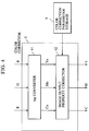
- the configuration of the color corrector 3 is shown in Fig. 4.
- a log converter 41 converts RGB data output from the color image information storage 2 into C O M O Y O data, and an image output characteristic corrector 42 outputs CMY data obtained by correction in accordance with the output characteristic of the image output 5 in the image processing set based on the parameters from the color correction parameter storage 9.
- the image output characteristic corrector 42 performs, for example, masking using a 3 ⁇ 3 matrix computation or gradation correction.
- the configuration of the image processor 4 is shown in Fig. 5.
- a density controller 51 performs density control on the CMY data, which is corrected by the color corrector 3 in accordance with the output characteristic of the image output device 5, according to the parameters set by the device setter 6. The density is controlled by ⁇ corrections corresponding to respective C, M and Y colors.
- a binarizer 52 binarizes C N , M N and Y N data obtained by the density control by using dither patterns set by the device setter 6.
- the above-mentioned devices are controlled by a CPU 12 by using a RAM 14 as a work memory according to programs stored in a ROM 13.
- a main processing routine is started in response to a command to generate color correction parameters.
- color chart output data is generated by the pattern generator 10, subjected to necessary image processing by the image processor 4, and printed out on paper or the like as a color chart from the image output 5 (Step S101). Since no color correction is made to the color chart output from the image output 5, both the image processing characteristic of the image processor 4 and the characteristic of the image output 5 are reflected in the color chart.
- the output color chart is read and converted into color chart read data by the document reader 1, and transmitted to the color correction parameter generator 8 (Step S102).
- the color correction parameter generator 8 transmits a control signal Q to the device setter 6 on receipt of the color chart read data.
- the device setter 6 stores, in the setting condition storage 7, an image processing setting of the image processor 4 when this color chart is output (Step S103).
- the color correction parameter generator 8 Based on the received color chart read data and color chart output data, the color correction parameter generator 8 generates color correction parameters for color correction best-suited to the output device in view of the characteristic of the image output 5 in the image processing setting of the image processor 4 when the color chart is output (Step S104).
- the color correction parameters generated by the color correction parameter generator 8 are stored in the color correction parameter storage 9 (Step S105).
- the color correction parameters and the device setting values are respectively stored in the color correction parameter storage 9 and the device setter 6 in correspondence with each other.
- the above procedure allows device setting conditions, which are fit for the color corrector 3 to perform color correction according to color correction parameters, to be stored in the setting condition storage 7 when the color correction parameters are generated.
- a plurality of pais of color correction parameters and device setting values can be stored by repeating the above procedure several times on arbitrary device setting conditions.
- color correction parameters are generated corresponding to the plurality of device setting values.
- color correction parameters are generated corresponding to the device setting values of the density controller 51 and the device setting values of the binarizer 52 set according to directions from the user.
- the operation shown in Fig. 2 be performed not only at shipment of the apparatus, but periodically or freely, for example, at replacement of the image output 5 and maintenance of the output device, or when required by the user.
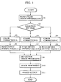
- a main processing routine is started in response to an image output start command.
- a color document is read by the document reader 1, and the read data is temporarily stored in the image information storage 2 as color image information (R, G and B color signals) (Step S1).
- Step S2 When one of the color correction parameters generated by the above-mentioned color correction parameter generation process is selected according to the device setting made through the operating portion by the user (or one of the parameters is preselected by the user), control is directed to one of branches A, B and C in Fig. 3 according to the selection (Step S2). Subsequently, the color image information read from the image information storage 2 is subjected to color correction, which is best-suited to the output device in view of the characteristic of the image input 5 in the color corrector 3 according to the color correction parameter selected from the color correction parameter storage 9 in Step S2, and converted into C, M and Y color signals. At this time, a control signal P identifying the selected color correction parameter is transmitted from the color corrector 3 to the device setter 6 (Step S3, S4 or S5).
- the device setter 6 reads the device setting value corresponding to the color correction parameter selected in Step S2 from the setting condition storage 7 with reference to the control signal P (Step S6, S7 or S8), and sets image processing of the image processor 4 inherent in the output device according to the read device setting value (Step S9).
- Image processing such as ink density control and binarization, set by the device setter 6 is applied on the C, M and Y color signals in the image processor 4 for carrying out image processing inherent in the output device, by which the C, M and Y signals are converted into C', M' and Y' color signals (Step S10).
- These C', M' and Y' color signals are supplied to the image output 5, which prints out a color image on paper (or cloth or a plastic sheet) (Step S11).
- color correction parameters best-suited to color correction in view of the type and characteristic of the output device are generated based on the output color chart and stored in the color correction parameter storage 9. Furthermore, device setting conditions best-suited to the color correction are set and stored in the setting condition storage 7. The output device is automatically adjusted to one of the device setting conditions best-suited to the present color correction based on such stored data. Therefore, an image can be automatically output in the best condition for the present color correction. Furthermore, when the color correction parameters are generated, the device setting conditions fit for color correction using the color correction parameters are stored in the setting condition storage 7, by which color correction is allowed to be performed in view of the device characteristic on an arbitrary device setting condition.
- R, G and B color signals are output from the color image information storage 2 and C', M' and Y' color signals are input to the image output 5 in the above embodiment, there is no special reason for limiting signals to such signals. These color signals may be replaced with color signals respectively depending on the characteristics of the output device. Similarly, although the color signals are converted from R, G and B into C, M and Y in the color corrector 3, other color signals may be used if color correction is performed in view of the type and characteristics of the output device.
- the data may be previously stored in a predetermined area of the color image information storage 2, and a color chart for generating the color correction parameters may be printed out from the image output 5 by using the stored data.
- color correction is performed according to the color correction parameters generated by the color correction parameter generator 8 in the above embodiment, similar effects to those of the above embodiment can be obtained in the present invention by previously storing a plurality of color correction parameters and a plurality of device setting values respectively in predetermined memories, sequentially pairing the color correction parameters and the device setting values based on the color chart read data and the image processing setting at color chart output, and then selectively using one of the pairs according to the selection of color correction by the user, that is, the selection of the color correction parameter by the user to carry out color correction and image processing.
- the binarizer 52 in the above embodiment may switch between, for example, the dither method and the error diffusion method.
- the image processor 4 may switch between other kinds of image processes, for example, a single color mode and a full-color mode, or a YMC three-color recording mode and a YMCK four-color recording mode.
- the present invention may be applied to a system constituted by a plurality of devices, or one apparatus comprising one such device.
- the pattern generator 10 may hold a plurality of color chart data corresponding to image processes, for example, color chart data for binarization and color chart data for density control.
- the present invention may be applied to a case in which the system or the apparatus is provided with a program for carrying out the present invention.
- the image output of the present invention may be applied to a head for jetting droplets by film boiling with heat energy, and a recording method using such head.
- the above-mentioned image processing is not limited to ink density control and dither patterning in binarization, and may be related to, for example, the control of the process amount, such as charging voltage, in electrophotography.
Applications Claiming Priority (3)
| Application Number | Priority Date | Filing Date | Title |
|---|---|---|---|
| JP9267794 | 1994-04-28 | ||
| JP92677/94 | 1994-04-28 | ||
| JP09267794A JP3305495B2 (ja) | 1994-04-28 | 1994-04-28 | 画像処理装置および画像処理方法 |
Publications (3)
| Publication Number | Publication Date |
|---|---|
| EP0680199A2 true EP0680199A2 (fr) | 1995-11-02 |
| EP0680199A3 EP0680199A3 (fr) | 1996-05-08 |
| EP0680199B1 EP0680199B1 (fr) | 2002-07-03 |
Family
ID=14061123
Family Applications (1)
| Application Number | Title | Priority Date | Filing Date |
|---|---|---|---|
| EP95302769A Expired - Lifetime EP0680199B1 (fr) | 1994-04-28 | 1995-04-25 | Procédé et appareil de traitement d'image |
Country Status (4)
| Country | Link |
|---|---|
| US (1) | US5835243A (fr) |
| EP (1) | EP0680199B1 (fr) |
| JP (1) | JP3305495B2 (fr) |
| DE (1) | DE69527228T2 (fr) |
Cited By (2)
| Publication number | Priority date | Publication date | Assignee | Title |
|---|---|---|---|---|
| EP0757472A2 (fr) * | 1995-07-31 | 1997-02-05 | Canon Kabushiki Kaisha | Appareil et procédé de traitement d'image |
| EP0825552A2 (fr) * | 1996-08-23 | 1998-02-25 | Canon Kabushiki Kaisha | Appareil de formation d'image, et appareil et méthode de contrÔle associé |
Families Citing this family (16)
| Publication number | Priority date | Publication date | Assignee | Title |
|---|---|---|---|---|
| JP3290870B2 (ja) * | 1995-11-17 | 2002-06-10 | ブラザー工業株式会社 | 色変換調整方法および装置 |
| US6091518A (en) * | 1996-06-28 | 2000-07-18 | Fuji Xerox Co., Ltd. | Image transfer apparatus, image transmitter, profile information transmitter, image receiver/reproducer, storage medium, image receiver, program transmitter, and image color correction apparatus |
| JP3209402B2 (ja) * | 1996-11-01 | 2001-09-17 | 富士ゼロックス株式会社 | 画像処理装置 |
| JPH10271344A (ja) * | 1997-03-27 | 1998-10-09 | Sharp Corp | カラー画像処理装置 |
| JP3598737B2 (ja) * | 1997-06-09 | 2004-12-08 | 富士ゼロックス株式会社 | カラー画像転送処理装置及び方法、カラー画像復元処理装置及び方法、並びにカラー画像転送システム |
| JP2000101836A (ja) | 1998-09-28 | 2000-04-07 | Canon Inc | 画像形成装置、画像処理方法および記録媒体 |
| JP3638228B2 (ja) * | 1999-06-11 | 2005-04-13 | コニカミノルタビジネステクノロジーズ株式会社 | 画像出力システム |
| JP3604972B2 (ja) | 1999-09-17 | 2004-12-22 | キヤノン株式会社 | 画像処理方法、装置および記録媒体 |
| JP4402850B2 (ja) * | 2001-03-16 | 2010-01-20 | 富士フイルム株式会社 | 鑑賞用データ補正方法および装置並びに記録媒体 |
| JP3787534B2 (ja) * | 2002-05-20 | 2006-06-21 | キヤノン株式会社 | 画像処理装置、画像処理方法及び画像処理プログラム |
| JP5054980B2 (ja) * | 2007-01-10 | 2012-10-24 | 株式会社リコー | カラー画像処理制御装置 |
| EP2319696A4 (fr) * | 2009-01-14 | 2012-03-28 | Mimaki Eng Kk | Programme, procédé de formation d'image et système d'impression |
| JP2010283687A (ja) * | 2009-06-05 | 2010-12-16 | Ricoh Co Ltd | プログラム、情報処理装置、階調補正パラメータ生成方法、記憶媒体 |
| JP5995511B2 (ja) * | 2012-05-07 | 2016-09-21 | キヤノン株式会社 | 画像形成装置 |
| JP2013258537A (ja) | 2012-06-12 | 2013-12-26 | Canon Inc | 撮像装置、及びその画像表示方法 |
| WO2016183744A1 (fr) * | 2015-05-15 | 2016-11-24 | SZ DJI Technology Co., Ltd. | Système et procédé de correction de couleur |
Citations (6)
| Publication number | Priority date | Publication date | Assignee | Title |
|---|---|---|---|---|
| EP0369778A2 (fr) * | 1988-11-15 | 1990-05-23 | Canon Kabushiki Kaisha | Appareil d'enregistrement d'images |
| US4929978A (en) * | 1987-10-23 | 1990-05-29 | Matsushita Electric Industrial Co., Ltd. | Color correction method for color copier utilizing correction table derived from printed color samples |
| US4970584A (en) * | 1985-05-15 | 1990-11-13 | Ricoh Company, Ltd. | Method and apparatus for the compensation of color detection |
| JPH03129971A (ja) * | 1989-10-16 | 1991-06-03 | Canon Inc | 画像読取装置 |
| EP0518525A2 (fr) * | 1991-06-12 | 1992-12-16 | Hewlett-Packard Company | Calibrage automatique d'images |
| US5184214A (en) * | 1989-08-08 | 1993-02-02 | Fuji Photo Film Co., Ltd. | Image output system |
Family Cites Families (17)
| Publication number | Priority date | Publication date | Assignee | Title |
|---|---|---|---|---|
| US5253048A (en) * | 1986-01-14 | 1993-10-12 | Canon Kabushiki Kaisha | Color image processing apparatus |
| EP0266186B1 (fr) * | 1986-10-29 | 1993-09-29 | Canon Kabushiki Kaisha | Appareil pour lire des images en couleurs ou pour enregistrer des images en couleurs |
| JPH06100861B2 (ja) * | 1987-06-03 | 1994-12-12 | コニカ株式会社 | カラ−画像形成装置 |
| US5014124A (en) * | 1988-02-25 | 1991-05-07 | Ricoh Company, Ltd. | Digital image processing apparatus |
| JP2578947B2 (ja) * | 1988-10-13 | 1997-02-05 | 富士写真フイルム株式会社 | 網点データ作成方法 |
| US4977448A (en) * | 1988-12-16 | 1990-12-11 | Matsushita Electric Industrial Co., Ltd. | Color image processing apparatus having exact color reproduction capability |
| US5153925A (en) * | 1989-04-27 | 1992-10-06 | Canon Kabushiki Kaisha | Image processing apparatus |
| EP0395404B1 (fr) * | 1989-04-27 | 1999-12-01 | Canon Kabushiki Kaisha | Appareil de traitement d'images |
| JPH03274963A (ja) * | 1990-03-26 | 1991-12-05 | Canon Inc | フアクシミリ装置 |
| DE69132304T2 (de) * | 1990-04-27 | 2000-12-21 | Canon Kk | Aufzeichnungsgerät mit Aufzeichnungsköpfen |
| US5345320A (en) * | 1990-11-29 | 1994-09-06 | Minolta Camera Kabushiki Kaisha | Color image data processing apparatus comprising monochrome pixel detector |
| EP0496600B1 (fr) * | 1991-01-25 | 1997-01-02 | Canon Kabushiki Kaisha | Apparail de traitement d'image |
| US5394250A (en) * | 1991-03-10 | 1995-02-28 | Canon Kabushiki Kaisha | Image processing capable of handling multi-level image data without deterioration of image quality in highlight areas |
| JP2985332B2 (ja) * | 1991-03-25 | 1999-11-29 | ソニー株式会社 | カラービデオ静止画像処理システム |
| JP3263821B2 (ja) * | 1992-01-29 | 2002-03-11 | コニカ株式会社 | カラー画像形成装置 |
| JPH05336373A (ja) * | 1992-06-04 | 1993-12-17 | Toshiba Corp | 画像記録装置 |
| US5589954A (en) * | 1993-05-28 | 1996-12-31 | Ricoh Company, Ltd. | γ-correction curve selecting apparatus and a γ-correction curve creating apparatus |
-
1994
- 1994-04-28 JP JP09267794A patent/JP3305495B2/ja not_active Expired - Fee Related
-
1995
- 1995-04-25 EP EP95302769A patent/EP0680199B1/fr not_active Expired - Lifetime
- 1995-04-25 DE DE69527228T patent/DE69527228T2/de not_active Expired - Lifetime
-
1997
- 1997-06-13 US US08/874,577 patent/US5835243A/en not_active Expired - Lifetime
Patent Citations (6)
| Publication number | Priority date | Publication date | Assignee | Title |
|---|---|---|---|---|
| US4970584A (en) * | 1985-05-15 | 1990-11-13 | Ricoh Company, Ltd. | Method and apparatus for the compensation of color detection |
| US4929978A (en) * | 1987-10-23 | 1990-05-29 | Matsushita Electric Industrial Co., Ltd. | Color correction method for color copier utilizing correction table derived from printed color samples |
| EP0369778A2 (fr) * | 1988-11-15 | 1990-05-23 | Canon Kabushiki Kaisha | Appareil d'enregistrement d'images |
| US5184214A (en) * | 1989-08-08 | 1993-02-02 | Fuji Photo Film Co., Ltd. | Image output system |
| JPH03129971A (ja) * | 1989-10-16 | 1991-06-03 | Canon Inc | 画像読取装置 |
| EP0518525A2 (fr) * | 1991-06-12 | 1992-12-16 | Hewlett-Packard Company | Calibrage automatique d'images |
Non-Patent Citations (1)
| Title |
|---|
| PATENT ABSTRACTS OF JAPAN vol. 15 no. 343 (E-1106) ,30 August 1991 & JP-A-03 129971 (CANON) 3 June 1991, * |
Cited By (6)
| Publication number | Priority date | Publication date | Assignee | Title |
|---|---|---|---|---|
| EP0757472A2 (fr) * | 1995-07-31 | 1997-02-05 | Canon Kabushiki Kaisha | Appareil et procédé de traitement d'image |
| EP0757472A3 (fr) * | 1995-07-31 | 1997-10-29 | Canon Kk | Appareil et procédé de traitement d'image |
| US5828816A (en) * | 1995-07-31 | 1998-10-27 | Canon Kabushiki Kaisha | Image processing apparatus and image processing method |
| EP0825552A2 (fr) * | 1996-08-23 | 1998-02-25 | Canon Kabushiki Kaisha | Appareil de formation d'image, et appareil et méthode de contrÔle associé |
| EP0825552A3 (fr) * | 1996-08-23 | 1999-02-24 | Canon Kabushiki Kaisha | Appareil de formation d'image, et appareil et méthode de contrÔle associé |
| US5933676A (en) * | 1996-08-23 | 1999-08-03 | Canon Kabushiki Kaisha | Image forming apparatus, and control apparatus and method therefor |
Also Published As
| Publication number | Publication date |
|---|---|
| EP0680199A3 (fr) | 1996-05-08 |
| DE69527228T2 (de) | 2003-01-16 |
| EP0680199B1 (fr) | 2002-07-03 |
| JP3305495B2 (ja) | 2002-07-22 |
| JPH07298072A (ja) | 1995-11-10 |
| US5835243A (en) | 1998-11-10 |
| DE69527228D1 (de) | 2002-08-08 |
Similar Documents
| Publication | Publication Date | Title |
|---|---|---|
| US5835243A (en) | Image processing apparatus and method | |
| EP0562596B1 (fr) | Procédé et appareil de traitement d'images en couleur | |
| US7180625B2 (en) | Printer controller, image forming apparatus and storage medium | |
| EP0484900B1 (fr) | Méthode et appareil pour modifier la densité des couleurs dans une imprimante | |
| US8861031B2 (en) | Printing using a selected color material | |
| JP3133779B2 (ja) | 画像処理装置 | |
| JP2000101836A (ja) | 画像形成装置、画像処理方法および記録媒体 | |
| JPH10233920A (ja) | 画像処理装置 | |
| JP2000190572A (ja) | 画像処理方法およびプリントシステム | |
| US5555093A (en) | Image processing apparatus and method thereof | |
| JPH11123856A (ja) | 画像形成パラメータ補正装置 | |
| US6281919B1 (en) | Stencil-making device | |
| JP2006210981A (ja) | 画像処理装置、画像処理システム、画像処理方法、画像処理プログラムおよび画像処理プログラムを記録した記録媒体 | |
| EP0582421B1 (fr) | Dispositif de traitement des images | |
| EP1424849B1 (fr) | Procedè de commande d'impression, appareil de creation de données d'image et des données pour la generation d'image | |
| JP3020987B2 (ja) | カラー画像形成装置のカラーバランスの調整方法 | |
| JP3794071B2 (ja) | 記録装置およびその階調制御方法 | |
| JPH11187279A (ja) | 画像処理装置及び方法 | |
| EP0480397A2 (fr) | Procédé et appareil de sortie de couleurs | |
| JP3103313B2 (ja) | カラー画像処理装置 | |
| JP3539648B2 (ja) | 画像処理装置 | |
| JP2022044179A (ja) | 画像形成装置 | |
| JPH099085A (ja) | 画像形成装置および画像処理方法 | |
| JPH08265586A (ja) | 画像処理装置 | |
| JP2001186322A (ja) | パッチチャートおよび画像処理装置 |
Legal Events
| Date | Code | Title | Description |
|---|---|---|---|
| PUAI | Public reference made under article 153(3) epc to a published international application that has entered the european phase |
Free format text: ORIGINAL CODE: 0009012 |
|
| AK | Designated contracting states |
Kind code of ref document: A2 Designated state(s): DE FR GB IT NL |
|
| PUAL | Search report despatched |
Free format text: ORIGINAL CODE: 0009013 |
|
| AK | Designated contracting states |
Kind code of ref document: A3 Designated state(s): DE FR GB IT NL |
|
| 17P | Request for examination filed |
Effective date: 19960918 |
|
| 17Q | First examination report despatched |
Effective date: 19970211 |
|
| GRAG | Despatch of communication of intention to grant |
Free format text: ORIGINAL CODE: EPIDOS AGRA |
|
| GRAG | Despatch of communication of intention to grant |
Free format text: ORIGINAL CODE: EPIDOS AGRA |
|
| GRAH | Despatch of communication of intention to grant a patent |
Free format text: ORIGINAL CODE: EPIDOS IGRA |
|
| GRAH | Despatch of communication of intention to grant a patent |
Free format text: ORIGINAL CODE: EPIDOS IGRA |
|
| GRAA | (expected) grant |
Free format text: ORIGINAL CODE: 0009210 |
|
| AK | Designated contracting states |
Kind code of ref document: B1 Designated state(s): DE FR GB IT NL |
|
| PG25 | Lapsed in a contracting state [announced via postgrant information from national office to epo] |
Ref country code: NL Free format text: LAPSE BECAUSE OF FAILURE TO SUBMIT A TRANSLATION OF THE DESCRIPTION OR TO PAY THE FEE WITHIN THE PRESCRIBED TIME-LIMIT Effective date: 20020703 Ref country code: IT Free format text: LAPSE BECAUSE OF FAILURE TO SUBMIT A TRANSLATION OF THE DESCRIPTION OR TO PAY THE FEE WITHIN THE PRESCRIBED TIME-LIMIT;WARNING: LAPSES OF ITALIAN PATENTS WITH EFFECTIVE DATE BEFORE 2007 MAY HAVE OCCURRED AT ANY TIME BEFORE 2007. THE CORRECT EFFECTIVE DATE MAY BE DIFFERENT FROM THE ONE RECORDED. Effective date: 20020703 |
|
| REF | Corresponds to: |
Ref document number: 69527228 Country of ref document: DE Date of ref document: 20020808 |
|
| ET | Fr: translation filed | ||
| NLV1 | Nl: lapsed or annulled due to failure to fulfill the requirements of art. 29p and 29m of the patents act | ||
| PLBE | No opposition filed within time limit |
Free format text: ORIGINAL CODE: 0009261 |
|
| STAA | Information on the status of an ep patent application or granted ep patent |
Free format text: STATUS: NO OPPOSITION FILED WITHIN TIME LIMIT |
|
| 26N | No opposition filed |
Effective date: 20030404 |
|
| PGFP | Annual fee paid to national office [announced via postgrant information from national office to epo] |
Ref country code: GB Payment date: 20130418 Year of fee payment: 19 Ref country code: DE Payment date: 20130430 Year of fee payment: 19 |
|
| PGFP | Annual fee paid to national office [announced via postgrant information from national office to epo] |
Ref country code: FR Payment date: 20130517 Year of fee payment: 19 |
|
| REG | Reference to a national code |
Ref country code: DE Ref legal event code: R119 Ref document number: 69527228 Country of ref document: DE |
|
| GBPC | Gb: european patent ceased through non-payment of renewal fee |
Effective date: 20140425 |
|
| REG | Reference to a national code |
Ref country code: FR Ref legal event code: ST Effective date: 20141231 |
|
| PG25 | Lapsed in a contracting state [announced via postgrant information from national office to epo] |
Ref country code: DE Free format text: LAPSE BECAUSE OF NON-PAYMENT OF DUE FEES Effective date: 20141101 Ref country code: GB Free format text: LAPSE BECAUSE OF NON-PAYMENT OF DUE FEES Effective date: 20140425 |
|
| REG | Reference to a national code |
Ref country code: DE Ref legal event code: R119 Ref document number: 69527228 Country of ref document: DE Effective date: 20141101 |
|
| PG25 | Lapsed in a contracting state [announced via postgrant information from national office to epo] |
Ref country code: FR Free format text: LAPSE BECAUSE OF NON-PAYMENT OF DUE FEES Effective date: 20140430 |