EP0677603A2 - Combing machine - Google Patents
Combing machine Download PDFInfo
- Publication number
- EP0677603A2 EP0677603A2 EP95110324A EP95110324A EP0677603A2 EP 0677603 A2 EP0677603 A2 EP 0677603A2 EP 95110324 A EP95110324 A EP 95110324A EP 95110324 A EP95110324 A EP 95110324A EP 0677603 A2 EP0677603 A2 EP 0677603A2
- Authority
- EP
- European Patent Office
- Prior art keywords
- cotton
- combing
- winding
- pair
- transport rollers
- Prior art date
- Legal status (The legal status is an assumption and is not a legal conclusion. Google has not performed a legal analysis and makes no representation as to the accuracy of the status listed.)
- Granted
Links
Images
Classifications
-
- D—TEXTILES; PAPER
- D01—NATURAL OR MAN-MADE THREADS OR FIBRES; SPINNING
- D01G—PRELIMINARY TREATMENT OF FIBRES, e.g. FOR SPINNING
- D01G19/00—Combing machines
- D01G19/06—Details
- D01G19/08—Feeding apparatus
Definitions
- the invention relates to a method and a device for preparing running cotton ends of windings in a combing machine provided with several combing heads, each combing head being presented with a winding for combing out and each combing head being provided with a detector device for determining the point in time at which the Cotton tape has almost completely run out of a first roll.
- a detector device in such a combing machine, e.g. with a photocell or a light barrier, which switches off the machine when the end of the cotton tape runs off the roll.
- the carrying device is then loaded with a new wad of cotton by hand or by a transport device.
- the beginning of the cotton tape from the new roll is then placed manually on the (possibly torn to the correct length) end of the cotton tape from the previous roll and connected to it by pressing, after which the machine can start again.
- this process is very time-consuming and creates different attachment points.
- This device is intended for changing an individual roll on a combing head, the roll change being carried out while the machine is running, that is to say without interrupting the combing process.
- the transport system for adding additional reserve windings is heavily loaded by the respective change of a single winding.
- the object of the invention is to propose a method or a device, wherein the outgoing cotton end of all windings can be prepared easily and uniformly.
- a detector device is expediently provided for determining the point in time at which the first cotton band has almost completely run off the first lap. At this point in time, the detector device starts a control device which then actuates the means mentioned for severing the first cotton band.
- a winding transport device for feeding a new winding to the carrier device can then be actuated, and means for cutting through the second cotton band can then be actuated.
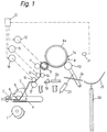
- Fig. 1 the essential parts of a combing head are shown in a schematic representation corresponding approximately to a vertical section.
- the essential combing tools of the combing head are a round comb 1, a fixed comb 2, two tear-off cylinders 3 and a pair of pliers with a pair of lower pliers 4 and an upper pliers 5 which can be pivoted with respect to the lower pliers 7 is supplied.
- the cotton tape 7 comes from a roll 8, which is carried by a carrier device, which in the embodiment shown consists of two parallel winding rolls 9 and 10, on which the roll 8 rests.
- Said transport roller pair 9, 11 is formed in the embodiment shown by the front winding roller 9 and a pressure roller 11 cooperating with it.
- a pair of transport rollers separated from the front winding roller 9 could also be provided for the cotton coming from the winding 8.
- the pair of transport rollers 9, 11 is driven by a controlled drive device 12.
- the means for severing the cotton are set up to tear the cotton after the pair of transport rollers 9, 11.
- a second pair of transport rollers 13, 14 is arranged after the first pair of transport rollers 9, 11 and is driven by a second controlled drive device 15.
- the two pairs of transport rollers 9, 11 and 13, 14 run at the same peripheral speeds.
- the drive devices 12 and 15 are controlled as explained below so that they rotate the two pairs of transport rollers 9, 11 and 13, 14 at different peripheral speeds and / or in different directions, so that the Cotton tape 7 tears between the two pairs of transport rollers. It is e.g.
- the device for connecting a first cotton end to a second cotton end has a pair of press rollers 16, 17, which is driven by a drive device 18, and a movable deflection element for at least one of two cotton ends to be connected to one another.
- the deflection element is a slide 19 arranged in the direction of movement of the cotton band 7 in front of the pair of press rollers 16, 17, which is e.g. is moved by a cylinder-piston unit 20.
- Fig. 1 the combing head described is shown in normal operation.
- the cotton tape 7 is unwound from the winding 8 by the rotation of the winding roller 9, through which the same circumferential speed rotating pairs of transport rollers 13, 14 and 16, 17 are fed to the combing tools 1-5 and combed out by them.
- the cotton tape 7, however, has almost completely run out of the winding 8 in FIG. 1.
- a detector device for example by a photocell 21, which detects the passage of the end 7a of the cotton tape 7 on the core 8a of the winding 8, for example by referring to the different brightnesses and / or colors of the cotton tape 7 and the winding core 8a responds.
- the detector device 21 emits a signal to a control device 22, which thereupon controls the drive devices 12, 15 and 18 and further drive devices, which will be described below, in the combing machine in such a way that a winding change is carried out automatically.
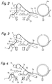
- control device 22 actuates a cylinder / piston unit 23 which swings the rear winding roller 10 downward, as shown in FIG. 2.
- the almost empty winding core 8a therefore rolls under the action of gravity on an inclined guide 24 to the rear except for a collecting device in the form of a trough-shaped plate 25.
- the remaining cotton band 7 is unwound from the core 8a.
- the control device 22 then controls the drive device 12 (FIG. 1) in such a way that it stops the pair of transport rollers 9, 11 or rotates in the opposite direction.
- the cotton belt 7 between the two pairs of transport rollers 9, 11 and 13, 14 is therefore torn by the second pair of transport rollers 13, 14, which rotates normally, that is, a new, rear cotton end 7b at a precisely defined point on the combing tools 1-5 running cotton tape 7 formed, as shown in Fig. 3.
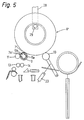
- the second pair of transport rollers 13, 14 and the pair of press rollers 16, 17 continue to rotate until the newly formed rear cotton end 7b is just in front of the pair of press rollers 16, 17, as shown in FIG. 4. Then the drive device 18 of the press roller pair 16, 17 is switched off, and at the same time the combing tools 1-6 (FIG. 1) are stopped.
- the separated rear end section 7c of the cotton band 7 is now still held in this pair of transport rollers 9, 11, as shown in FIG. 4.
- the pair of transport rollers 9, 11 is therefore now rotated together with the second pair of transport rollers 13, 14 again in the forward direction in order to convey the end section 7c into a suction channel 26, through which it is removed.
- the end section 7c can also be removed by a suction channel 27 arranged further back, in that the first pair of transport rollers 9, 11 is now rotated in the opposite direction until the beginning of the end section 7c falls into this suction channel 27.
- the first pair of transport rollers 9, 11 has already been rotated sufficiently in the opposite direction for the tearing of the cotton tape 7, then the beginning of the end section 7c can easily fall into the suction channel 27 and no further rotation is required.
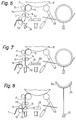
- control device 22 actuates a winding transport device, of which only one arm 28 with a support pin 29 is shown in FIG. 5.
- the winding transport device brings up a new cotton roll 8 'and places it on the winding rollers 9 and 10.
- the winding roller 9 rotates the cotton roll 8 'resting on it.
- the jacket of the winding roller 9 is permeable to air, e.g. perforated, and in its interior a stationary tube 9a is arranged, which has a slot 9b in an upper region.
- a vacuum is now generated in this tube 9a, so that air is sucked in through the slot 9b and the air-permeable jacket of the winding roller 9.
- the beginning 7a 'of the cotton tape 7' from the new roll 8 'is therefore sucked in by the winding roller 9 as soon as it reaches it.
- the beginning 7 a ′ lies against the circumference of the winding roller 9, as shown in FIG. 5.
- the cotton belt 7 'is then moved downwards by the pairs of transport rollers 9, 11 and 13, 14.
- the first pair of transport rollers 9, 11 is stopped after a predetermined period of time, or the second pair of transport rollers 13, 14 is accelerated with respect to the first pair 9, 11.
- the cotton band 7 ' is torn between the two pairs of transport rollers 9, 11 and 13, 14, that is to say a new front cotton end 7b' is formed at a precisely defined point on the cotton band 7 'coming from the roll 8', as shown in FIG 6 shown.
- the severed front end section 7c 'of the cotton band 7' is then sucked into the suction channel 26 and removed through it after it has passed completely through the second pair of transport rollers 13, 14.
- the two pairs of transport rollers 9, 11 and 13, 14 then continue to run at the same peripheral speeds and move the cotton belt 7 'coming from the roll 8' downward.
- the control device 22 actuates the cylinder-piston unit 20 in order to move the slide 19 to the left against the press roller pair 16, 17.
- the slider 19 comes into contact with the front cotton end 7b 'as shown in FIG. 8 and places the same on the rear cotton end 7b of the cotton tape 7, which is still held in the nip of the press roller pair 16, 17 and protrudes out of it, partially resting on the circumference of the lower press roll 17.
- FIG. 8 it is also shown that the collecting device 25 with the empty winding core 8a lying thereon has been lifted into an upper position by a drive device in the form of a cylinder-piston unit 30. In this upper position, the empty winding core 8a is then picked up and removed by the winding transport device 28, 29 (FIG. 5), whereupon the collecting device 25 is lowered again into its starting position according to FIG. 1.
- the described combing head can be arranged in a combing machine in a group of combing heads in which common drive devices for the combing tools 1-5 of all combing heads of the group are provided.
- the control device 22 is then also assigned to all combing heads in the group together.
- the drive devices controlled by the control device 22, in particular the drive devices 12, 15 and 18 and the cylinder-piston units 20, 23 and 30 as well as the means for generating negative pressure in the front winding roller 9 and in the suction channels 26 and 27 and the winding transport device (28 , 29) can also be assigned to all combing heads of the group together (although in principle the common control device could also control separate drive devices etc.).
- a separate detector device 21 (FIG. 1) is arranged for each comb head of the group.
- the detector device 21 in question emits a signal to the common control device 22, which then carries out the winding change described above for all combing heads in the group at the same time.
- the common control device 22 which then carries out the winding change described above for all combing heads in the group at the same time.
- different lengths of the cotton tape 7 may still be present on the winding cores 8a in the various combing heads of the group; the new rear cotton ends 7b formed by the simultaneous severing (tearing) of the cotton strips 7 between the pairs of transport rollers 9, 11 and 13, 14 are then at the same level in all combing heads of the group.
- the new front cotton ends 7b 'formed by tearing the new cotton strips 7' lie at the same height in all combing heads, even if the cotton wool beginning 7a 'is not exactly on the new cotton wool rolls 8' fed by the winding transport device (28, 29) same place of the circumference. Therefore, the front cotton ends 7b 'in all combing heads can be connected to the rear cotton ends 7b in the same way without any problems by the slide 19 (or a common slide 19) and the press rollers 16, 17.
- both the cotton tape 7 from the roll 8 and afterwards the cotton tape 7 'from the new roll 8' are cut or torn by different driving of the two pairs of transport rollers 9, 11 and 13, 14 when changing the roll.
- separate means for cutting the cotton tape 7 and for cutting the cotton tape 7 'could of course also be arranged.
- a second pair of transport rollers does not necessarily have to be used for the severing, but instead other severing means which can be actuated by the control device 22 could also be provided.
Landscapes
- Engineering & Computer Science (AREA)
- Textile Engineering (AREA)
- Preliminary Treatment Of Fibers (AREA)
- Replacing, Conveying, And Pick-Finding For Filamentary Materials (AREA)
- Filamentary Materials, Packages, And Safety Devices Therefor (AREA)
Abstract
Description
Die Erfindung bezieht sich auf ein verfahren bzw. eine Vorrichtung zum vorbereiten auslaufender Watteenden von Wickeln in einer mit mehreren Kämmköpfen versehenen Kämmaschine, wobei jedem Kämmkopf ein Wickel zum Auskämmen vorgelegt wird und jeder Kämmkopf mit einer Detektoreinrichtung versehen ist zum Feststellen des Zeitpunkts, in welchem das Watteband von einem ersten Wickel annähernd vollständig abgelaufen ist.The invention relates to a method and a device for preparing running cotton ends of windings in a combing machine provided with several combing heads, each combing head being presented with a winding for combing out and each combing head being provided with a detector device for determining the point in time at which the Cotton tape has almost completely run out of a first roll.
Es ist bekannt, in einer solchen Kämmaschine eine Detektoreinrichtung anzuordnen, z.B. mit einer Fotozelle oder einer Lichtschranke, welche die Maschine abstellt, wenn das Ende des Wattebandes von dem Wickel abläuft. Die Trageinrichtung wird dann von Hand oder von einer Transportvorrichtung mit einem neuen Wattewickel beschickt. Der Anfang des Wattebandes vom neuen Wickel wird anschliessend manuell auf das (ggf. auf richtige Länge abgerissene) Ende des Wattebandes vom vorherigen Wickel aufgelegt und durch Andrücken mit diesem verbunden, worauf die Maschine wieder anlaufen kann. Dieses Verfahren ist jedoch sehr zeitaufwendig und erzeugt unterschiedliche Ansetzstellen.It is known to arrange a detector device in such a combing machine, e.g. with a photocell or a light barrier, which switches off the machine when the end of the cotton tape runs off the roll. The carrying device is then loaded with a new wad of cotton by hand or by a transport device. The beginning of the cotton tape from the new roll is then placed manually on the (possibly torn to the correct length) end of the cotton tape from the previous roll and connected to it by pressing, after which the machine can start again. However, this process is very time-consuming and creates different attachment points.
Aus der US-A-2 559 074 ist eine gattungsgemässe Vorrichtung zur automatischen Nachführung eines Wattebandes eines neuen Wickels bekannt. Der neue Wickel wird oberhalb des in Arbeit befindlichen ersten Wickels in einer Reserveposition gehalten und beim Auslaufen des ersten Wickels nach unten in die Abrollposition verschoben. Das neue Watteende muss in einer nach vorne herabhängenden Lage positioniert sein, damit es beim Absenkvorgang auf das auslaufende Watteende zu liegen kommt. Über ein Kammelement wird das auslaufende Watteende getrennt, um eine gleichbleibende Überlappung mit dem neuen Watteende zu erzielen.From US-A-2 559 074 a generic device for automatic tracking of a cotton tape of a new roll is known. The new reel is held in a reserve position above the first reel in progress and, when the first reel runs out, is moved down into the unwinding position. The new cotton end must be positioned in a forward-hanging position so that it comes to rest on the running cotton end during the lowering process. The outgoing cotton end is separated by a comb element in order to achieve a constant overlap with the new cotton end.
Diese Vorrichtung ist für einen Wechsel eines einzelnen Wickels an einem Kämmkopf vorgesehen, wobei der Wickelwechsel bei laufender Maschine, also ohne Unterbruch des Kämmprozesses durchgeführt wird. Durch den jeweiligen Wechsel eines einzelnen Wickels wird das Transportsystem für das Nachbringen weiterer Reservewickel stark belastet.This device is intended for changing an individual roll on a combing head, the roll change being carried out while the machine is running, that is to say without interrupting the combing process. The transport system for adding additional reserve windings is heavily loaded by the respective change of a single winding.
Die Aufgabe der Erfindung besteht darin, ein Verfahren bzw. eine Vorrichtung vorzuschlagen, wobei das auslaufende Watteende sämtlicher Wickel einfach und gleichmässig vorbereitet werden kann.The object of the invention is to propose a method or a device, wherein the outgoing cotton end of all windings can be prepared easily and uniformly.
Diese Aufgabe wird durch das vorgeschlagenen Verfahren nach Patentanspruch 1, bzw. durch die Vorrichtung nach Patentanspruch 3 gelöst. Durch die vorgeschlagene automatische Vorbereitung der Watteenden, und zwar gleichzeitig an allen Kämmköpfen, erhält man eine schnelle und gleichmässige Vorbereitung an allen Kämmköpfen.This object is achieved by the proposed method according to claim 1, or by the device according to claim 3. The proposed automatic preparation of the cotton ends, at the same time on all combing heads, results in quick and uniform preparation on all combing heads.
Dazu ist zweckmässigerweise eine Detektoreinrichtung vorgesehen zum Feststellen des Zeitpunktes, in welchem das erste Watteband vom ersten Wickel annähernd vollständig abgelaufen ist. Die Detektoreinrichtung startet in diesem Zeitpunkt eine Steuereinrichtung, welche dann die genannten Mittel zum Durchtrennen des ersten Wattebandes betätigt. Danach kann eine Wickeltransportvorrichtung zum Zuführen eines neuen Wickels zu der Trageinrichtung betätigt werden, und hierauf können Mittel zum Durchtrennen des zweiten Wattebandes betätigt werden.For this purpose, a detector device is expediently provided for determining the point in time at which the first cotton band has almost completely run off the first lap. At this point in time, the detector device starts a control device which then actuates the means mentioned for severing the first cotton band. A winding transport device for feeding a new winding to the carrier device can then be actuated, and means for cutting through the second cotton band can then be actuated.
Ausführungsbeispiele der Erfindung werden nachstehend anhand der Zeichnungen näher erläutert. In diesen zeigen:
- Fig. 1
- schematisch einen Kämmkopf einer erfindungsgemässen Kämmaschine und
- Fig. 2 bis Fig. 8
- je einen Ausschnitt aus Fig. 1 bei anderen Stellungen und Betriebszuständen der Teile.
- Fig. 1
- schematically a combing head of a combing machine according to the invention and
- 2 to 8
- 1 excerpt from FIG. 1 at different positions and operating states of the parts.
In Fig. 1 sind die wesentlichen Teile eines Kämmkopfes in einer etwa einem Vertikalschnitt entsprechenden schematischen Darstellung gezeigt. Die wesentlichen Kämmwerkzeuge des Kämmkopfes sind ein Rundkamm 1, ein Fixkamm 2, zwei Abreisszylinder 3 und ein Zangenaggregat mit einer Unterzange 4 und einer bezüglich der Unterzange schwenkbaren Oberzange 5. In der Unterzange 4 ist ein antreibbarer Speisezylinder 6 gelagert, dem eine zu kämmende bandförmige Watte 7 zugeführt wird. Das Watteband 7 kommt von einem Wickel 8, der von einer Trageinrichtung getragen ist, welche in der dargestellten Ausführungsform aus zwei parallelen Wickelwalzen 9 und 10 besteht, auf denen der Wickel 8 aufliegt.In Fig. 1, the essential parts of a combing head are shown in a schematic representation corresponding approximately to a vertical section. The essential combing tools of the combing head are a round comb 1, a
Im Weg des Wattebandes 7 von dem Wickel 8 zu den Kämmwerkzeugen 1 - 5 sind ein Transportwalzenpaar 9,11, Mittel zum Durchtrennen der Watte und eine Einrichtung zum Verbinden eines ersten Watteendes 7b mit einem zweiten Watteende 7b' angeordnet, wobei das erste Watteende 7b ein hinteres Ende des zu den Kämmwerkzeugen laufenden Wattebandes ist und das zweite Watteende 7b' ein vorderes Ende eines von einem neuen Wickel kommenden Wattebandes 7' ist, wie im Nachstehenden noch erläutert wird.A pair of
Das genannte Transportwalzenpaar 9,11 wird in der dargestellten Ausführungsform von der vorderen Wickelwalze 9 und einer mit dieser zusammenwirkenden Andruckwalze 11 gebildet. Es könnte jedoch auch ein von der vorderen Wickelwalze 9 getrenntes Transportwalzenpaar für die vom Wickel 8 kommende Watte vorgesehen sein. Das Transportwalzenpaar 9,11 wird von einer gesteuerten Antriebseinrichtung 12 angetrieben.Said
Die Mittel zum Durchtrennen der Watte sind in der dargestellten Ausführungsform dazu eingerichtet, die Watte nach dem Transportwalzenpaar 9,11 zu zerreissen. Zu diesem Zweck ist nach dem ersten Transportwalzenpaar 9,11 ein zweites Transportwalzenpaar 13,14 angeordnet, das von einer zweiten gesteuerten Antriebseinrichtung 15 angetrieben wird. Im normalen Betrieb der Kämmaschine laufen die beiden Transportwalzenpaare 9,11 und 13,14 mit gleichen Umfangsgeschwindigkeiten. Wenn ein Watteband 7 durchtrennt bzw. zerrissen werden soll, werden die Antriebseinrichtungen 12 und 15 wie im Nachstehenden erläutert so gesteuert, dass sie die beiden Transportwalzenpaare 9,11 und 13,14 mit unterschiedlichen Umfangsgeschwindigkeiten und/oder in unterschiedlichen Richtungen drehen, so dass das Watteband 7 zwischen den beiden Transportwalzenpaaren reisst. Es ist z.B. möglich, das erste Transportwalzenpaar 9,11 stillzusetzen und das zweite Transportwalzenpaar 13,14 weiter anzutreiben oder das erste Walzenpaar 9,11 in entgegengesetzter Richtung anzutreiben, während das zweite Transportwalzenpaar 13,14 stillsteht. In beiden Fällen erfolgt eine Durchtrennung des Wattebandes.In the embodiment shown, the means for severing the cotton are set up to tear the cotton after the pair of
Die Einrichtung zum Verbinden eines ersten Watteendes mit einem zweiten Watteende besitzt ein Presswalzenpaar 16,17, das von einer Antriebseinrichtung 18 angetrieben wird, und ein bewegbares Auslenkelement für mindestens eines von zwei miteinander zu verbindenden Watteenden. In der dargestellten Ausführungsform ist das Auslenkelement ein in Bewegungsrichtung des Wattebandes 7 vor dem Presswalzenpaar 16,17 angeordneter Schieber 19, der z.B. von einem Zylinder-Kolben-Aggregat 20 bewegt wird.The device for connecting a first cotton end to a second cotton end has a pair of
In Fig. 1 ist der beschriebene Kämmkopf im normalen Betrieb dargestellt. Das Watteband 7 wird durch die Drehung der Wickelwalze 9 von dem Wickel 8 abgewickelt, durch die mit der gleichen Umfangsgeschwindigkeit drehenden Transportwalzenpaare 13,14 und 16,17 den Kämmwerkzeugen 1-5 zugeführt und von diesen ausgekämmt. Das Watteband 7 ist jedoch in Fig. 1 von dem Wickel 8 schon beinahe vollständig abgelaufen. Dieser Zeitpunkt wird nun von einer Detektoreinrichtung festgestellt, beispielsweise von einer Fotozelle 21, welche den Durchlauf des Endes 7a des Wattebandes 7 auf dem Kern 8a des Wickels 8 feststellt, indem sie etwa auf die unterschiedlichen Helligkeiten und/oder Farben des Wattebandes 7 und des Wickelkerns 8a anspricht. Natürlich sind auch andere Detektoreinrichtungen zu dem angegebenen Zweck brauchbar. Die Detektoreinrichtung 21 gibt ein Signal an eine Steuereinrichtung 22 ab, welche darauf die Antriebseinrichtungen 12,15 und 18 und weitere, nachstehend noch beschriebene Antriebseinrichtungen in der Kämmaschine so steuert, dass automatisch ein Wickelwechsel durchgeführt wird.In Fig. 1 the combing head described is shown in normal operation. The
Zuerst betätigt die Steuereinrichtung 22 ein Zylinder-Kolbenaggregat 23, welches die hintere Wickelwalze 10 nach unten wegschwenkt, wie in Fig. 2 gezeigt. Der fast leere Wikkelkern 8a rollt daher unter der Einwirkung der Schwerkraft auf einer geneigten Führung 24 nach hinten bis auf eine Auffangeinrichtung in Form eines muldenförmigen Bleches 25. Das verbliebene Watteband 7 wird dabei von dem Kern 8a abgewickelt.First, the
Dann steuert die Steuereinrichtung 22 die Antriebseinrichtung 12 (Fig. 1) so, dass diese das Transportwalzenpaar 9,11 stillsetzt oder in umgekehrter Richtung dreht. Durch das normal weiterdrehende zweite Transportwalzenpaar 13,14 wird daher das Watteband 7 zwischen den beiden Transportwalzenpaaren 9,11 und 13,14 zerrissen, das heisst, es wird an einer genau definierten Stelle ein neues hinteres Watteende 7b an dem zu den Kämmwerkzeugen 1-5 laufenden Watteband 7 gebildet, wie in Fig. 3 dargestellt.The
Das zweite Transportwalzenpaar 13,14 und das Presswalzenpaar 16,17 drehen weiter, bis das neu gebildete hintere Watteende 7b wie in Fig. 4 gezeigt kurz vor dem Presswalzenpaar 16,17 steht. Dann wird die Antriebseinrichtung 18 des Presswalzenpaares 16,17 abgeschaltet, und gleichzeitig werden auch die Kämmwerkzeuge 1-6 (Fig. 1) stillgesetzt.The second pair of
Wenn das erste Transportwalzenpaar 9,11 für das Zerreissen des Wattebandes 7 einfach stillgesetzt worden ist, dann ist der abgetrennte hintere Endabschnitt 7c des Wattebandes 7 jetzt noch in diesem Transportwalzenpaar 9, 11 festgehalten, wie Fig. 4 zeigt. Das Transportwalzenpaar 9,11 wird daher nun zusammen mit dem zweiten Transportwalzenpaar 13,14 wieder in Vorwärtsrichtung gedreht, um den Endabschnitt 7c in einen Absaugkanal 26 zu fördern, durch welchen er entfernt wird. Stattdessen kann der Endabschnitt 7c auch durch einen weiter hinten angeordneten Absaugkanal 27 entfernt werden, indem das erste Transportwalzenpaar 9,11 nun in umgekehrter Richtung gedreht wird, bis der Anfang des Endabschnittes 7c in diesen Absaugkanal 27 fällt. Wenn das erste Transportwalzenpaar 9,11 jedoch schon für das Zerreissen des Wattebandes 7 genügend in umgekehrter Richtung gedreht worden ist, dann kann der Anfang des Endabschnittes 7c ohne weiteres in den Absaugkanal 27 fallen und ist nun keine weitere Drehung mehr erforderlich.If the first pair of
Dann wird durch Betätigung des Zylinder-Kolben-Aggregates 23 die hintere Wickelwalze 10 wieder in ihre obere Stellung bzw. normale Arbeitsstellung zurückgeschwenkt.Then, by actuating the cylinder-
Danach betätigt die Steuereinrichtung 22 eine Wickeltransportvorrichtung, von der in Fig. 5 lediglich ein Arm 28 mit einem Tragzapfen 29 dargestellt ist. Die Wickeltransportvorrichtung führt einen neuen Wattewickel 8' heran und setzt diesen auf die Wickelwalzen 9 und 10.Thereafter, the
Danach werden die Transportwalzenpaare 9,11 und 13,14 in Vorwärtsrichtung gedreht. Die Wickelwalze 9 dreht den auf ihr aufliegenden Wattewickel 8'. Der Mantel der Wickelwalze 9 ist luftdurchlässig, z.B. perforiert, und in ihrem Inneren ist ein stationäres Rohr 9a angeordnet, welches in einem oberen Bereich einen Schlitz 9b aufweist. In diesem Rohr 9a wird nun ein Unterdruck erzeugt, so dass durch den Schlitz 9b und den luftdurchlässigen Mantel der Wickelwalze 9 hindurch Luft angesaugt wird. Der Anfang 7a' des Wattebandes 7' vom neuen Wickel 8' wird daher von der Wickelwalze 9 angesaugt, sobald er diese erreicht. Dadurch legt sich der Anfang 7a' wie in Fig. 5 gezeigt an den Umfang der Wickelwalze 9 an. Das Watteband 7' wird dann durch die Transportwalzenpaare 9,11 und 13,14 nach unten bewegt.Thereafter, the pairs of
Nachdem der Anfang 7a' des Wattebandes 7' durch das zweite Transportwalzenpaar 13,14 hindurchgetreten ist, wird nach Ablauf einer vorbestimmten Zeitspanne das erste Transportwalzenpaar 9,11 stillgesetzt oder das zweite Transportwalzenpaar 13,14 gegenüber dem ersten Paar 9,11 beschleunigt. Dadurch wir das Watteband 7' zwischen den beiden Transportwalzenpaaren 9,11 und 13,14 zerrissen, das heisst, es wird an einer genau definierten Stelle ein neues vorderes Watteende 7b' an dem vom Wickel 8' kommenden Watteband 7' gebildet, wie in Fig. 6 dargestellt.After the
Der abgetrennte vordere Endabschnitt 7c' des Wattebandes 7' wird dann, nachdem er ganz durch das zweite Transportwalzenpaar 13,14 hindurchgetreten ist, in den Absaugkanal 26 gesaugt und durch diesen entfernt.The severed front end section 7c 'of the cotton band 7' is then sucked into the
Die beiden Transportwalzenpaare 9,11 und 13,14 laufen danach mit gleichen Umfangsgeschwindigkeiten weiter und bewegen das vom Wickel 8' kommende Watteband 7' nach unten. Nachdem das neue vordere Watteende 7b' etwa die in Fig. 7 gezeigte Stellung vor dem Presswalzenpaar 16,17 bzw. zwischen diesem und dem Schieber 19 erreicht hat, betätigt die Steuereinrichtung 22 das Zylinder-Kolbenaggregat 20, um den Schieber 19 nach links gegen das Presswalzenpaar 16,17 zu bewegen. Der Schieber 19 tritt dabei wie in Fig. 8 gezeigt mit dem vorderen Watteende 7b' in Berührung und legt dasselbe auf das hintere Watteende 7b des Wattebandes 7, das immer noch in der Klemmstelle des Presswalzenpaares 16,17 gehalten ist und aus dieser heraus vorsteht, wobei es teilweise auf dem Umfang der unteren Presswalze 17 aufliegt.The two pairs of
Dann werden die Antriebseinrichtung 18 des Presswalzenpaares 16,17 und gleichzeitig auch die Antriebseinrichtungen der Kämmwerkzeuge 1-6 wieder eingeschaltet. Das hintere Watteende 7b des Wattebandes 7 wird mit dem darauf liegenden vorderen Wattende 7b' des Wattebandes 7' in das Presswalzenpaar 16,17 gezogen, das die beiden Watteenden 7b und 7b' zusammenpresst und miteinander verbindet. Dabei wird der Schieber 19 vom Zylinder-Kolbenaggregat wieder nach rechts zurückgezogen. Der Kämmkopf nimmt den normalen Betrieb wieder auf.Then the
In Fig. 8 ist noch gezeigt, dass die Auffangeinrichtung 25 mit dem auf dieser liegenden leeren Wickelkern 8a von einer Antriebseinrichtung in Form eines Zylinder-Kolbenaggregates 30 in eine obere Stellung gehoben worden ist. In dieser oberen Stellung wird der leere Wickelkern 8a dann von der Wickeltransportvorrichtung 28,29 (Fig. 5) erfasst und abgeführt, worauf die Auffangeinrichtung 25 wieder in ihre Ausgangsstellung gemäss Fig. 1 gesenkt wird.In FIG. 8 it is also shown that the collecting
Der beschriebene Kämmkopf kann in einer Kämmaschine in einer Gruppe von Kämmköpfen angeordnet sein, in der gemeinsame Antriebseinrichtungen für die Kämmwerkzeuge 1-5 aller Kämmköpfe der Gruppe vorgesehen sind. Die Steuereinrichtung 22 ist dann ebenfalls allen Kämmköpfen der Gruppe gemeinsam zugeordnet. Die von der Steuereinrichtung 22 gesteuerten Antriebseinrichtungen, insbesondere die Antriebseinrichtungen 12, 15 und 18 und die Zylinder-Kolbenaggregate 20, 23 und 30 sowie die Mittel zum Erzeugen von Unterdruck in der vorderen Wickelwalze 9 und in den Absaugkanälen 26 und 27 und die Wickeltransportvorrichtung (28,29) können ebenfalls allen Kämmköpfen der Gruppe gemeinsam zugeordnet sein (obwohl die gemeinsame Steuereinrichtung im Prinzip auch getrennte Antriebseinrichtungen usw. steuern könnte).The described combing head can be arranged in a combing machine in a group of combing heads in which common drive devices for the combing tools 1-5 of all combing heads of the group are provided. The
Hingegen ist für jeden Kämmkopf der Gruppe jeweils eine eigene Detektoreinrichtung 21 (Fig. 1) angeordnet. Sobald in einem der Kämmköpfe das Watteband 7 vom Wickel 8 annähernd vollständig abgelaufen ist, gibt die betreffende Detektoreinrichtung 21 ein Signal an die gemeinsame Steuereinrichtung 22 ab, welche darauf den im Vorstehenden beschriebenen Wickelwechsel bei allen Kämmköpfen der Gruppe gleichzeitig durchführt. Zu Beginn des Wickelwechsels können auf den Wickelkernen 8a in den verschiedenen Kämmköpfen der Gruppe noch unterschiedliche Längen des Wattebandes 7 vorhanden sein; die durch das gleichzeitige Durchtrennen (Zerreissen) der Wattebänder 7 zwischen den Transportwalzenpaaren 9,11 und 13,14 gebildeten neuen hinteren Watteenden 7b liegen dann jedoch in allen Kämmköpfen der Gruppe auf gleicher Höhe. Ebenso liegen nachher die durch das Zerreissen der neuen Wattebänder 7' gebildeten neuen vorderen Watteenden 7b' in allen Kämmköpfen auf gleicher Höhe, auch wenn auf den von der Wickeltransportvorrichtung (28,29) zugeführten neuen Wattewickeln 8' der Watteanfang 7a' nicht genau an der gleichen Stelle des Umfangs lag. Daher können dann durch die Schiebe 19 (bzw. einen gemeinsamen Schieber 19) und die Presswalzen 16,17 die vorderen Watteenden 7b' in allen Kämmköpfen in gleicher Weise problemlos mit den hinteren Watteenden 7b verbunden werden.On the other hand, a separate detector device 21 (FIG. 1) is arranged for each comb head of the group. As soon as the
Im beschriebenen Kämmkopf werden beim Wickelwechsel sowohl das Watteband 7 vom Wickel 8 als auch nachher das Watteband 7' vom neuen Wickel 8' jeweils durch unterschiedliches Antreiben der beiden Transportwalzenpaare 9,11 und 13,14 durchtrennt bzw. zerrissen. In abgeänderten Ausführungsformen könnten aber natürlich auch gesonderte Mittel für das Durchtrennen des Wattebandes 7 und für das Durchtrennen des Wattebandes 7' angeordnet sein. Im übrigen muss für das Durchtrennen nicht unbedingt ein zweites Transportwalzenpaar verwendet werden, sondern es könnten stattdessen auch andere von der Steuereinrichtung 22 betätigbare Durchtrenneinrichtungen vorgesehen sein.In the combing head described, both the
Claims (3)
gekennzeichnet durch folgende Verfahrensschritte:
characterized by the following process steps:
dadurch gekennzeichnet, dass die Detektoreinrichtungen (21) mit einer Steuereinrichtung (22) verbunden sind, welche einerseits mit den Antriebseinrichtungen (12,15,18) der Kämmaschine und andererseits mit den Mitteln (13,14) für das Durchtrennen des Wattebandes (7) verbunden ist.Apparatus for preparing outgoing cotton ends for carrying out the method according to claim 1, wherein the combing machine is provided with a plurality of combing heads, the combing tools (1-6) and each have a carrying device (9, 10) for a winding (8, 8 '), and A detector device (21) is provided for each combing head for monitoring the point in time at which the cotton tape (7) has almost completely run off from a first roll.
characterized in that the detector devices (21) are connected to a control device (22) which is connected on the one hand to the drive devices (12, 15, 18) of the combing machine and on the other hand to the Means (13,14) for cutting the cotton tape (7) is connected.
Applications Claiming Priority (4)
| Application Number | Priority Date | Filing Date | Title |
|---|---|---|---|
| CH408688 | 1988-11-03 | ||
| CH4086/88A CH676249A5 (en) | 1988-11-03 | 1988-11-03 | |
| CH4086/88 | 1988-11-03 | ||
| EP89119485A EP0368059B1 (en) | 1988-11-03 | 1989-10-20 | Combing machine (lap piecing) |
Related Parent Applications (2)
| Application Number | Title | Priority Date | Filing Date |
|---|---|---|---|
| EP89119485.4 Division | 1989-10-20 | ||
| EP89119485A Division EP0368059B1 (en) | 1988-11-03 | 1989-10-20 | Combing machine (lap piecing) |
Publications (3)
| Publication Number | Publication Date |
|---|---|
| EP0677603A2 true EP0677603A2 (en) | 1995-10-18 |
| EP0677603A3 EP0677603A3 (en) | 1996-01-03 |
| EP0677603B1 EP0677603B1 (en) | 1999-07-28 |
Family
ID=4269566
Family Applications (2)
| Application Number | Title | Priority Date | Filing Date |
|---|---|---|---|
| EP95110324A Expired - Lifetime EP0677603B1 (en) | 1988-11-03 | 1989-10-20 | Combing machine |
| EP89119485A Expired - Lifetime EP0368059B1 (en) | 1988-11-03 | 1989-10-20 | Combing machine (lap piecing) |
Family Applications After (1)
| Application Number | Title | Priority Date | Filing Date |
|---|---|---|---|
| EP89119485A Expired - Lifetime EP0368059B1 (en) | 1988-11-03 | 1989-10-20 | Combing machine (lap piecing) |
Country Status (6)
| Country | Link |
|---|---|
| US (1) | US4996747A (en) |
| EP (2) | EP0677603B1 (en) |
| JP (1) | JPH02169729A (en) |
| CH (1) | CH676249A5 (en) |
| DD (1) | DD284914A5 (en) |
| DE (2) | DE58909853D1 (en) |
Cited By (2)
| Publication number | Priority date | Publication date | Assignee | Title |
|---|---|---|---|---|
| DE19739186A1 (en) * | 1997-09-08 | 1999-03-11 | Truetzschler Gmbh & Co Kg | Sliver splicing |
| EP1464739A1 (en) * | 2003-04-04 | 2004-10-06 | Marzoli S.p.A. | Lap-forming machine and process |
Families Citing this family (14)
| Publication number | Priority date | Publication date | Assignee | Title |
|---|---|---|---|---|
| JP2645421B2 (en) * | 1988-05-18 | 1997-08-25 | 株式会社原織機製作所 | Automatic splicing method and apparatus |
| JP2645423B2 (en) * | 1988-07-18 | 1997-08-25 | 株式会社原織機製作所 | Method and apparatus for automatically cutting and removing small ball wrap bobbins |
| US5077865A (en) * | 1989-11-03 | 1992-01-07 | Rieter Machine Works, Ltd. | Comber lap joining device with suction head for preparing ends |
| CH680670A5 (en) * | 1990-01-17 | 1992-10-15 | Rieter Ag Maschf | |
| JP2763968B2 (en) * | 1990-05-02 | 1998-06-11 | マシーネンフアブリーク リーテル アクチエンゲゼルシヤフト | Method of joining lap in lap processing machine and lap processing machine |
| CH681894A5 (en) * | 1990-10-22 | 1993-06-15 | Rieter Ag Maschf | |
| CH683191A5 (en) * | 1991-05-22 | 1994-01-31 | Rieter Ag Maschf | Means for collecting lap pieces which are separated in combing machines of cotton tapes. |
| EP0533618A1 (en) * | 1991-09-17 | 1993-03-24 | Maschinenfabrik Rieter Ag | Automatic lap transport |
| IT1401066B1 (en) * | 2010-07-23 | 2013-07-12 | Marzoli Combing & Flyer S P A Ora Marzoli S P A | LAPTOP DEVICE FOR A STRAINER |
| JP6194871B2 (en) * | 2014-11-06 | 2017-09-13 | 株式会社豊田自動織機 | Wrap splicer in comber |
| JP6372476B2 (en) * | 2015-11-02 | 2018-08-15 | 株式会社豊田自動織機 | Method and device for lap cutting in comber |
| DE102016108423A1 (en) * | 2016-05-06 | 2017-11-09 | Rieter Ingolstadt Gmbh | Method for handling a thread end and winding station |
| JP6766749B2 (en) * | 2017-05-18 | 2020-10-14 | 株式会社豊田自動織機 | Comb |
| CH717160A1 (en) | 2020-02-21 | 2021-08-31 | Rieter Ag Maschf | Combing machine with a lap guide device for an automatic lap piecer. |
Citations (1)
| Publication number | Priority date | Publication date | Assignee | Title |
|---|---|---|---|---|
| US2559074A (en) | 1945-05-17 | 1951-07-03 | Terrell Mach Co | Lap changer for combing machines |
Family Cites Families (9)
| Publication number | Priority date | Publication date | Assignee | Title |
|---|---|---|---|---|
| GB191510394A (en) * | 1915-07-17 | 1916-10-17 | John William Nasmith | Improvements in or relating to Combing Machines. |
| DE640041C (en) * | 1935-04-19 | 1936-12-19 | Saechs Textilmaschinenfabrik V | Device for tearing off and piling up the fibers on combed machines |
| DE853571C (en) * | 1942-02-14 | 1952-10-27 | Alsacienne Constr Meca | Device for placing food rolls on flat combed machines |
| US2895177A (en) * | 1953-10-12 | 1959-07-21 | Tmm Research Ltd | Textile combing machines |
| GB1058925A (en) * | 1962-08-22 | 1967-02-15 | Kureha Spinning Co Ltd | Process and apparatus for producing continuously combed sliver from carded sliver |
| CH625564A5 (en) * | 1977-08-24 | 1981-09-30 | Rieter Ag Maschf | |
| SU866013A1 (en) * | 1979-02-28 | 1981-09-23 | Всесоюзный Научно-Исследовательский Институт Легкого И Текстильного Машиностроения | Method and machine for combing fibrous lap |
| JP2676554B2 (en) * | 1989-07-10 | 1997-11-17 | ティーオーエー株式会社 | Pocket pager with shortening function |
| JP3004156B2 (en) * | 1993-09-22 | 2000-01-31 | セコム株式会社 | Automatic information transmission device |
-
1988
- 1988-11-03 CH CH4086/88A patent/CH676249A5/de not_active IP Right Cessation
-
1989
- 1989-10-20 EP EP95110324A patent/EP0677603B1/en not_active Expired - Lifetime
- 1989-10-20 EP EP89119485A patent/EP0368059B1/en not_active Expired - Lifetime
- 1989-10-20 DE DE58909853T patent/DE58909853D1/en not_active Expired - Fee Related
- 1989-10-20 DE DE58909569T patent/DE58909569D1/en not_active Expired - Fee Related
- 1989-10-31 JP JP1282089A patent/JPH02169729A/en active Pending
- 1989-11-03 US US07/431,431 patent/US4996747A/en not_active Expired - Fee Related
- 1989-11-03 DD DD89334232A patent/DD284914A5/en not_active IP Right Cessation
Patent Citations (1)
| Publication number | Priority date | Publication date | Assignee | Title |
|---|---|---|---|---|
| US2559074A (en) | 1945-05-17 | 1951-07-03 | Terrell Mach Co | Lap changer for combing machines |
Cited By (3)
| Publication number | Priority date | Publication date | Assignee | Title |
|---|---|---|---|---|
| DE19739186A1 (en) * | 1997-09-08 | 1999-03-11 | Truetzschler Gmbh & Co Kg | Sliver splicing |
| US6065191A (en) * | 1997-09-08 | 2000-05-23 | Trutzschler Gmbh & Co. Kg | Method and apparatus for splicing and feeding slivers |
| EP1464739A1 (en) * | 2003-04-04 | 2004-10-06 | Marzoli S.p.A. | Lap-forming machine and process |
Also Published As
| Publication number | Publication date |
|---|---|
| CH676249A5 (en) | 1990-12-28 |
| EP0677603A3 (en) | 1996-01-03 |
| DE58909569D1 (en) | 1996-02-22 |
| DE58909853D1 (en) | 1999-09-02 |
| EP0368059B1 (en) | 1996-01-10 |
| US4996747A (en) | 1991-03-05 |
| EP0368059A1 (en) | 1990-05-16 |
| DD284914A5 (en) | 1990-11-28 |
| EP0677603B1 (en) | 1999-07-28 |
| JPH02169729A (en) | 1990-06-29 |
Similar Documents
| Publication | Publication Date | Title |
|---|---|---|
| EP0677603B1 (en) | Combing machine | |
| DE2725105C2 (en) | Method for carrying out a piecing process and device for carrying out the method | |
| DE69115110T2 (en) | Textile machine. | |
| DE69311674T2 (en) | Method and device for overlapping plastic bulges | |
| EP0826615B1 (en) | Method and device for winding a paper web into a roll | |
| DE2544209C2 (en) | Method for piecing individual spinning units of an open-end spinning machine having a plurality of spinning units | |
| EP0792829A2 (en) | Method of and device for winding a paper web into a roll | |
| DE2350840A1 (en) | OPEN-END SPINNING MACHINE WITH A MOVABLE DEVICE FOR SPINNING | |
| DE19608842B4 (en) | Device and method for the web feed | |
| DE19708410A1 (en) | Ring spinner drawing unit | |
| DE3338833A1 (en) | METHOD AND DEVICE FOR SPINNING A YARN ON A SPINNING UNIT OF AN OE-FRICTION SPINNING MACHINE | |
| DD288812A5 (en) | INLAY TABLE AND METHOD FOR THE FEEDING OF FIBER CHANGERS | |
| EP0437807B1 (en) | Method for exchanging the cotton wool roll in at least one combing head of a combing machine | |
| DE2713355C2 (en) | Spinning can frame for feeding textile fiber slivers to a processing machine | |
| EP0401162B1 (en) | Combing machine | |
| DE2556237C2 (en) | Spinning machine system with several open-end spinning machines and at least one maintenance device | |
| DE4123205A1 (en) | METHOD AND DEVICE FOR SEPARATING TAPES | |
| CH693146A5 (en) | A device for connecting and supplying slivers. | |
| EP0176809B1 (en) | Circular knitting machine for making high-pile knitwear | |
| DE2629381A1 (en) | METHOD FOR MANUFACTURING A TAMPON AND DEVICE FOR CARRYING OUT THE METHOD | |
| EP0615009A1 (en) | Nipping point for lap | |
| DE202013102342U1 (en) | Splicing device for splicing cord material | |
| EP2267200A1 (en) | Procedure for operating a workstation and workstation of an open ended rotor spinning machine | |
| DE3513238A1 (en) | Device for winding unvulcanised rubber strips | |
| DE2760369C2 (en) |
Legal Events
| Date | Code | Title | Description |
|---|---|---|---|
| PUAI | Public reference made under article 153(3) epc to a published international application that has entered the european phase |
Free format text: ORIGINAL CODE: 0009012 |
|
| AC | Divisional application: reference to earlier application |
Ref document number: 368059 Country of ref document: EP |
|
| AK | Designated contracting states |
Kind code of ref document: A2 Designated state(s): CH DE IT LI |
|
| PUAL | Search report despatched |
Free format text: ORIGINAL CODE: 0009013 |
|
| AK | Designated contracting states |
Kind code of ref document: A3 Designated state(s): CH DE IT LI |
|
| 17P | Request for examination filed |
Effective date: 19960119 |
|
| 17Q | First examination report despatched |
Effective date: 19970903 |
|
| GRAG | Despatch of communication of intention to grant |
Free format text: ORIGINAL CODE: EPIDOS AGRA |
|
| GRAG | Despatch of communication of intention to grant |
Free format text: ORIGINAL CODE: EPIDOS AGRA |
|
| GRAH | Despatch of communication of intention to grant a patent |
Free format text: ORIGINAL CODE: EPIDOS IGRA |
|
| GRAH | Despatch of communication of intention to grant a patent |
Free format text: ORIGINAL CODE: EPIDOS IGRA |
|
| GRAA | (expected) grant |
Free format text: ORIGINAL CODE: 0009210 |
|
| AC | Divisional application: reference to earlier application |
Ref document number: 368059 Country of ref document: EP |
|
| AK | Designated contracting states |
Kind code of ref document: B1 Designated state(s): CH DE IT LI |
|
| REG | Reference to a national code |
Ref country code: CH Ref legal event code: EP |
|
| REF | Corresponds to: |
Ref document number: 58909853 Country of ref document: DE Date of ref document: 19990902 |
|
| ITF | It: translation for a ep patent filed | ||
| PLBE | No opposition filed within time limit |
Free format text: ORIGINAL CODE: 0009261 |
|
| STAA | Information on the status of an ep patent application or granted ep patent |
Free format text: STATUS: NO OPPOSITION FILED WITHIN TIME LIMIT |
|
| 26N | No opposition filed | ||
| PGFP | Annual fee paid to national office [announced via postgrant information from national office to epo] |
Ref country code: CH Payment date: 20041011 Year of fee payment: 16 |
|
| PG25 | Lapsed in a contracting state [announced via postgrant information from national office to epo] |
Ref country code: LI Free format text: LAPSE BECAUSE OF NON-PAYMENT OF DUE FEES Effective date: 20051031 Ref country code: CH Free format text: LAPSE BECAUSE OF NON-PAYMENT OF DUE FEES Effective date: 20051031 |
|
| REG | Reference to a national code |
Ref country code: CH Ref legal event code: PL |
|
| PGFP | Annual fee paid to national office [announced via postgrant information from national office to epo] |
Ref country code: DE Payment date: 20071025 Year of fee payment: 19 |
|
| PGFP | Annual fee paid to national office [announced via postgrant information from national office to epo] |
Ref country code: IT Payment date: 20071025 Year of fee payment: 19 |
|
| PG25 | Lapsed in a contracting state [announced via postgrant information from national office to epo] |
Ref country code: IT Free format text: LAPSE BECAUSE OF NON-PAYMENT OF DUE FEES Effective date: 20081020 Ref country code: DE Free format text: LAPSE BECAUSE OF NON-PAYMENT OF DUE FEES Effective date: 20090501 |