EP0677603A2 - Machine de peignage - Google Patents
Machine de peignage Download PDFInfo
- Publication number
- EP0677603A2 EP0677603A2 EP95110324A EP95110324A EP0677603A2 EP 0677603 A2 EP0677603 A2 EP 0677603A2 EP 95110324 A EP95110324 A EP 95110324A EP 95110324 A EP95110324 A EP 95110324A EP 0677603 A2 EP0677603 A2 EP 0677603A2
- Authority
- EP
- European Patent Office
- Prior art keywords
- cotton
- combing
- winding
- pair
- transport rollers
- Prior art date
- Legal status (The legal status is an assumption and is not a legal conclusion. Google has not performed a legal analysis and makes no representation as to the accuracy of the status listed.)
- Granted
Links
Images
Classifications
-
- D—TEXTILES; PAPER
- D01—NATURAL OR MAN-MADE THREADS OR FIBRES; SPINNING
- D01G—PRELIMINARY TREATMENT OF FIBRES, e.g. FOR SPINNING
- D01G19/00—Combing machines
- D01G19/06—Details
- D01G19/08—Feeding apparatus
Definitions
- the invention relates to a method and a device for preparing running cotton ends of windings in a combing machine provided with several combing heads, each combing head being presented with a winding for combing out and each combing head being provided with a detector device for determining the point in time at which the Cotton tape has almost completely run out of a first roll.
- a detector device in such a combing machine, e.g. with a photocell or a light barrier, which switches off the machine when the end of the cotton tape runs off the roll.
- the carrying device is then loaded with a new wad of cotton by hand or by a transport device.
- the beginning of the cotton tape from the new roll is then placed manually on the (possibly torn to the correct length) end of the cotton tape from the previous roll and connected to it by pressing, after which the machine can start again.
- this process is very time-consuming and creates different attachment points.
- This device is intended for changing an individual roll on a combing head, the roll change being carried out while the machine is running, that is to say without interrupting the combing process.
- the transport system for adding additional reserve windings is heavily loaded by the respective change of a single winding.
- the object of the invention is to propose a method or a device, wherein the outgoing cotton end of all windings can be prepared easily and uniformly.
- a detector device is expediently provided for determining the point in time at which the first cotton band has almost completely run off the first lap. At this point in time, the detector device starts a control device which then actuates the means mentioned for severing the first cotton band.
- a winding transport device for feeding a new winding to the carrier device can then be actuated, and means for cutting through the second cotton band can then be actuated.
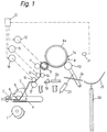
- Fig. 1 the essential parts of a combing head are shown in a schematic representation corresponding approximately to a vertical section.
- the essential combing tools of the combing head are a round comb 1, a fixed comb 2, two tear-off cylinders 3 and a pair of pliers with a pair of lower pliers 4 and an upper pliers 5 which can be pivoted with respect to the lower pliers 7 is supplied.
- the cotton tape 7 comes from a roll 8, which is carried by a carrier device, which in the embodiment shown consists of two parallel winding rolls 9 and 10, on which the roll 8 rests.
- Said transport roller pair 9, 11 is formed in the embodiment shown by the front winding roller 9 and a pressure roller 11 cooperating with it.
- a pair of transport rollers separated from the front winding roller 9 could also be provided for the cotton coming from the winding 8.
- the pair of transport rollers 9, 11 is driven by a controlled drive device 12.
- the means for severing the cotton are set up to tear the cotton after the pair of transport rollers 9, 11.
- a second pair of transport rollers 13, 14 is arranged after the first pair of transport rollers 9, 11 and is driven by a second controlled drive device 15.
- the two pairs of transport rollers 9, 11 and 13, 14 run at the same peripheral speeds.
- the drive devices 12 and 15 are controlled as explained below so that they rotate the two pairs of transport rollers 9, 11 and 13, 14 at different peripheral speeds and / or in different directions, so that the Cotton tape 7 tears between the two pairs of transport rollers. It is e.g.
- the device for connecting a first cotton end to a second cotton end has a pair of press rollers 16, 17, which is driven by a drive device 18, and a movable deflection element for at least one of two cotton ends to be connected to one another.
- the deflection element is a slide 19 arranged in the direction of movement of the cotton band 7 in front of the pair of press rollers 16, 17, which is e.g. is moved by a cylinder-piston unit 20.
- Fig. 1 the combing head described is shown in normal operation.
- the cotton tape 7 is unwound from the winding 8 by the rotation of the winding roller 9, through which the same circumferential speed rotating pairs of transport rollers 13, 14 and 16, 17 are fed to the combing tools 1-5 and combed out by them.
- the cotton tape 7, however, has almost completely run out of the winding 8 in FIG. 1.
- a detector device for example by a photocell 21, which detects the passage of the end 7a of the cotton tape 7 on the core 8a of the winding 8, for example by referring to the different brightnesses and / or colors of the cotton tape 7 and the winding core 8a responds.
- the detector device 21 emits a signal to a control device 22, which thereupon controls the drive devices 12, 15 and 18 and further drive devices, which will be described below, in the combing machine in such a way that a winding change is carried out automatically.
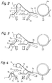
- control device 22 actuates a cylinder / piston unit 23 which swings the rear winding roller 10 downward, as shown in FIG. 2.
- the almost empty winding core 8a therefore rolls under the action of gravity on an inclined guide 24 to the rear except for a collecting device in the form of a trough-shaped plate 25.
- the remaining cotton band 7 is unwound from the core 8a.
- the control device 22 then controls the drive device 12 (FIG. 1) in such a way that it stops the pair of transport rollers 9, 11 or rotates in the opposite direction.
- the cotton belt 7 between the two pairs of transport rollers 9, 11 and 13, 14 is therefore torn by the second pair of transport rollers 13, 14, which rotates normally, that is, a new, rear cotton end 7b at a precisely defined point on the combing tools 1-5 running cotton tape 7 formed, as shown in Fig. 3.
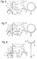
- the second pair of transport rollers 13, 14 and the pair of press rollers 16, 17 continue to rotate until the newly formed rear cotton end 7b is just in front of the pair of press rollers 16, 17, as shown in FIG. 4. Then the drive device 18 of the press roller pair 16, 17 is switched off, and at the same time the combing tools 1-6 (FIG. 1) are stopped.
- the separated rear end section 7c of the cotton band 7 is now still held in this pair of transport rollers 9, 11, as shown in FIG. 4.
- the pair of transport rollers 9, 11 is therefore now rotated together with the second pair of transport rollers 13, 14 again in the forward direction in order to convey the end section 7c into a suction channel 26, through which it is removed.
- the end section 7c can also be removed by a suction channel 27 arranged further back, in that the first pair of transport rollers 9, 11 is now rotated in the opposite direction until the beginning of the end section 7c falls into this suction channel 27.
- the first pair of transport rollers 9, 11 has already been rotated sufficiently in the opposite direction for the tearing of the cotton tape 7, then the beginning of the end section 7c can easily fall into the suction channel 27 and no further rotation is required.
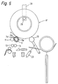
- control device 22 actuates a winding transport device, of which only one arm 28 with a support pin 29 is shown in FIG. 5.
- the winding transport device brings up a new cotton roll 8 'and places it on the winding rollers 9 and 10.
- the winding roller 9 rotates the cotton roll 8 'resting on it.
- the jacket of the winding roller 9 is permeable to air, e.g. perforated, and in its interior a stationary tube 9a is arranged, which has a slot 9b in an upper region.
- a vacuum is now generated in this tube 9a, so that air is sucked in through the slot 9b and the air-permeable jacket of the winding roller 9.
- the beginning 7a 'of the cotton tape 7' from the new roll 8 'is therefore sucked in by the winding roller 9 as soon as it reaches it.
- the beginning 7 a ′ lies against the circumference of the winding roller 9, as shown in FIG. 5.
- the cotton belt 7 'is then moved downwards by the pairs of transport rollers 9, 11 and 13, 14.
- the first pair of transport rollers 9, 11 is stopped after a predetermined period of time, or the second pair of transport rollers 13, 14 is accelerated with respect to the first pair 9, 11.
- the cotton band 7 ' is torn between the two pairs of transport rollers 9, 11 and 13, 14, that is to say a new front cotton end 7b' is formed at a precisely defined point on the cotton band 7 'coming from the roll 8', as shown in FIG 6 shown.
- the severed front end section 7c 'of the cotton band 7' is then sucked into the suction channel 26 and removed through it after it has passed completely through the second pair of transport rollers 13, 14.
- the two pairs of transport rollers 9, 11 and 13, 14 then continue to run at the same peripheral speeds and move the cotton belt 7 'coming from the roll 8' downward.
- the control device 22 actuates the cylinder-piston unit 20 in order to move the slide 19 to the left against the press roller pair 16, 17.
- the slider 19 comes into contact with the front cotton end 7b 'as shown in FIG. 8 and places the same on the rear cotton end 7b of the cotton tape 7, which is still held in the nip of the press roller pair 16, 17 and protrudes out of it, partially resting on the circumference of the lower press roll 17.
- FIG. 8 it is also shown that the collecting device 25 with the empty winding core 8a lying thereon has been lifted into an upper position by a drive device in the form of a cylinder-piston unit 30. In this upper position, the empty winding core 8a is then picked up and removed by the winding transport device 28, 29 (FIG. 5), whereupon the collecting device 25 is lowered again into its starting position according to FIG. 1.
- the described combing head can be arranged in a combing machine in a group of combing heads in which common drive devices for the combing tools 1-5 of all combing heads of the group are provided.
- the control device 22 is then also assigned to all combing heads in the group together.
- the drive devices controlled by the control device 22, in particular the drive devices 12, 15 and 18 and the cylinder-piston units 20, 23 and 30 as well as the means for generating negative pressure in the front winding roller 9 and in the suction channels 26 and 27 and the winding transport device (28 , 29) can also be assigned to all combing heads of the group together (although in principle the common control device could also control separate drive devices etc.).
- a separate detector device 21 (FIG. 1) is arranged for each comb head of the group.
- the detector device 21 in question emits a signal to the common control device 22, which then carries out the winding change described above for all combing heads in the group at the same time.
- the common control device 22 which then carries out the winding change described above for all combing heads in the group at the same time.
- different lengths of the cotton tape 7 may still be present on the winding cores 8a in the various combing heads of the group; the new rear cotton ends 7b formed by the simultaneous severing (tearing) of the cotton strips 7 between the pairs of transport rollers 9, 11 and 13, 14 are then at the same level in all combing heads of the group.
- the new front cotton ends 7b 'formed by tearing the new cotton strips 7' lie at the same height in all combing heads, even if the cotton wool beginning 7a 'is not exactly on the new cotton wool rolls 8' fed by the winding transport device (28, 29) same place of the circumference. Therefore, the front cotton ends 7b 'in all combing heads can be connected to the rear cotton ends 7b in the same way without any problems by the slide 19 (or a common slide 19) and the press rollers 16, 17.
- both the cotton tape 7 from the roll 8 and afterwards the cotton tape 7 'from the new roll 8' are cut or torn by different driving of the two pairs of transport rollers 9, 11 and 13, 14 when changing the roll.
- separate means for cutting the cotton tape 7 and for cutting the cotton tape 7 'could of course also be arranged.
- a second pair of transport rollers does not necessarily have to be used for the severing, but instead other severing means which can be actuated by the control device 22 could also be provided.
Landscapes
- Engineering & Computer Science (AREA)
- Textile Engineering (AREA)
- Preliminary Treatment Of Fibers (AREA)
- Replacing, Conveying, And Pick-Finding For Filamentary Materials (AREA)
- Filamentary Materials, Packages, And Safety Devices Therefor (AREA)
Applications Claiming Priority (4)
| Application Number | Priority Date | Filing Date | Title |
|---|---|---|---|
| CH408688 | 1988-11-03 | ||
| CH4086/88A CH676249A5 (fr) | 1988-11-03 | 1988-11-03 | |
| CH4086/88 | 1988-11-03 | ||
| EP89119485A EP0368059B1 (fr) | 1988-11-03 | 1989-10-20 | Machine de peignage(rattachage de nappe) |
Related Parent Applications (2)
| Application Number | Title | Priority Date | Filing Date |
|---|---|---|---|
| EP89119485.4 Division | 1989-10-20 | ||
| EP89119485A Division EP0368059B1 (fr) | 1988-11-03 | 1989-10-20 | Machine de peignage(rattachage de nappe) |
Publications (3)
| Publication Number | Publication Date |
|---|---|
| EP0677603A2 true EP0677603A2 (fr) | 1995-10-18 |
| EP0677603A3 EP0677603A3 (fr) | 1996-01-03 |
| EP0677603B1 EP0677603B1 (fr) | 1999-07-28 |
Family
ID=4269566
Family Applications (2)
| Application Number | Title | Priority Date | Filing Date |
|---|---|---|---|
| EP95110324A Expired - Lifetime EP0677603B1 (fr) | 1988-11-03 | 1989-10-20 | Machine de peignage |
| EP89119485A Expired - Lifetime EP0368059B1 (fr) | 1988-11-03 | 1989-10-20 | Machine de peignage(rattachage de nappe) |
Family Applications After (1)
| Application Number | Title | Priority Date | Filing Date |
|---|---|---|---|
| EP89119485A Expired - Lifetime EP0368059B1 (fr) | 1988-11-03 | 1989-10-20 | Machine de peignage(rattachage de nappe) |
Country Status (6)
| Country | Link |
|---|---|
| US (1) | US4996747A (fr) |
| EP (2) | EP0677603B1 (fr) |
| JP (1) | JPH02169729A (fr) |
| CH (1) | CH676249A5 (fr) |
| DD (1) | DD284914A5 (fr) |
| DE (2) | DE58909853D1 (fr) |
Cited By (2)
| Publication number | Priority date | Publication date | Assignee | Title |
|---|---|---|---|---|
| DE19739186A1 (de) * | 1997-09-08 | 1999-03-11 | Truetzschler Gmbh & Co Kg | Vorrichtung zum Verbinden und Zuführen von Faserbändern, insbesondere Karden- oder Streckenbändern |
| EP1464739A1 (fr) * | 2003-04-04 | 2004-10-06 | Marzoli S.p.A. | Assembleuse de rubans et procédé correspondant |
Families Citing this family (14)
| Publication number | Priority date | Publication date | Assignee | Title |
|---|---|---|---|---|
| JP2645421B2 (ja) * | 1988-05-18 | 1997-08-25 | 株式会社原織機製作所 | ラップを自動継ぎする方法と装置 |
| JP2645423B2 (ja) * | 1988-07-18 | 1997-08-25 | 株式会社原織機製作所 | 小玉ラップボビンを自動切断除去する方法と装置 |
| US5077865A (en) * | 1989-11-03 | 1992-01-07 | Rieter Machine Works, Ltd. | Comber lap joining device with suction head for preparing ends |
| CH680670A5 (fr) * | 1990-01-17 | 1992-10-15 | Rieter Ag Maschf | |
| JP2763968B2 (ja) * | 1990-05-02 | 1998-06-11 | マシーネンフアブリーク リーテル アクチエンゲゼルシヤフト | ラップ処理機械におけるラップの接合方法及びラップ処理機械 |
| CH681894A5 (fr) * | 1990-10-22 | 1993-06-15 | Rieter Ag Maschf | |
| CH683191A5 (de) * | 1991-05-22 | 1994-01-31 | Rieter Ag Maschf | Einrichtung zum Sammeln von Wattestücken, die in Kämmaschinen von Wattebändern abgetrennt werden. |
| EP0533618A1 (fr) * | 1991-09-17 | 1993-03-24 | Maschinenfabrik Rieter Ag | Transport automatique de rouleaux de nappe |
| IT1401066B1 (it) * | 2010-07-23 | 2013-07-12 | Marzoli Combing & Flyer S P A Ora Marzoli S P A | Dispositivo di formazione della teletta per uno stiroriunitore |
| JP6194871B2 (ja) * | 2014-11-06 | 2017-09-13 | 株式会社豊田自動織機 | コーマにおけるラップ継ぎ装置 |
| JP6372476B2 (ja) * | 2015-11-02 | 2018-08-15 | 株式会社豊田自動織機 | コーマにおけるラップ切断方法及びラップ切断装置 |
| DE102016108423A1 (de) * | 2016-05-06 | 2017-11-09 | Rieter Ingolstadt Gmbh | Verfahren zum Handhaben eines Fadenendes und Spulstelle |
| JP6766749B2 (ja) * | 2017-05-18 | 2020-10-14 | 株式会社豊田自動織機 | コーマ |
| CH717160A1 (de) | 2020-02-21 | 2021-08-31 | Rieter Ag Maschf | Kämmmaschine mit einer Watteführungsvorrichtung für einen automatischen Wickelansetzer. |
Citations (1)
| Publication number | Priority date | Publication date | Assignee | Title |
|---|---|---|---|---|
| US2559074A (en) | 1945-05-17 | 1951-07-03 | Terrell Mach Co | Lap changer for combing machines |
Family Cites Families (9)
| Publication number | Priority date | Publication date | Assignee | Title |
|---|---|---|---|---|
| GB191510394A (en) * | 1915-07-17 | 1916-10-17 | John William Nasmith | Improvements in or relating to Combing Machines. |
| DE640041C (de) * | 1935-04-19 | 1936-12-19 | Saechs Textilmaschinenfabrik V | Vorrichtung zum Abreissen und Anstueckeln der Faserbaerte an Kaemmaschinen |
| DE853571C (de) * | 1942-02-14 | 1952-10-27 | Alsacienne Constr Meca | Vorrichtung zum Auflegen von Speisewickeln auf Flachkaemmaschinen |
| US2895177A (en) * | 1953-10-12 | 1959-07-21 | Tmm Research Ltd | Textile combing machines |
| GB1058925A (en) * | 1962-08-22 | 1967-02-15 | Kureha Spinning Co Ltd | Process and apparatus for producing continuously combed sliver from carded sliver |
| CH625564A5 (fr) * | 1977-08-24 | 1981-09-30 | Rieter Ag Maschf | |
| SU866013A1 (ru) * | 1979-02-28 | 1981-09-23 | Всесоюзный Научно-Исследовательский Институт Легкого И Текстильного Машиностроения | Способ гребнечесани волокнистой ленты и гребнечесальна машина дл его осуществлени |
| JP2676554B2 (ja) * | 1989-07-10 | 1997-11-17 | ティーオーエー株式会社 | 短縮機能付きポケット・ページャ |
| JP3004156B2 (ja) * | 1993-09-22 | 2000-01-31 | セコム株式会社 | 自動情報送信装置 |
-
1988
- 1988-11-03 CH CH4086/88A patent/CH676249A5/de not_active IP Right Cessation
-
1989
- 1989-10-20 EP EP95110324A patent/EP0677603B1/fr not_active Expired - Lifetime
- 1989-10-20 EP EP89119485A patent/EP0368059B1/fr not_active Expired - Lifetime
- 1989-10-20 DE DE58909853T patent/DE58909853D1/de not_active Expired - Fee Related
- 1989-10-20 DE DE58909569T patent/DE58909569D1/de not_active Expired - Fee Related
- 1989-10-31 JP JP1282089A patent/JPH02169729A/ja active Pending
- 1989-11-03 US US07/431,431 patent/US4996747A/en not_active Expired - Fee Related
- 1989-11-03 DD DD89334232A patent/DD284914A5/de not_active IP Right Cessation
Patent Citations (1)
| Publication number | Priority date | Publication date | Assignee | Title |
|---|---|---|---|---|
| US2559074A (en) | 1945-05-17 | 1951-07-03 | Terrell Mach Co | Lap changer for combing machines |
Cited By (3)
| Publication number | Priority date | Publication date | Assignee | Title |
|---|---|---|---|---|
| DE19739186A1 (de) * | 1997-09-08 | 1999-03-11 | Truetzschler Gmbh & Co Kg | Vorrichtung zum Verbinden und Zuführen von Faserbändern, insbesondere Karden- oder Streckenbändern |
| US6065191A (en) * | 1997-09-08 | 2000-05-23 | Trutzschler Gmbh & Co. Kg | Method and apparatus for splicing and feeding slivers |
| EP1464739A1 (fr) * | 2003-04-04 | 2004-10-06 | Marzoli S.p.A. | Assembleuse de rubans et procédé correspondant |
Also Published As
| Publication number | Publication date |
|---|---|
| CH676249A5 (fr) | 1990-12-28 |
| EP0677603A3 (fr) | 1996-01-03 |
| DE58909569D1 (de) | 1996-02-22 |
| DE58909853D1 (de) | 1999-09-02 |
| EP0368059B1 (fr) | 1996-01-10 |
| US4996747A (en) | 1991-03-05 |
| EP0368059A1 (fr) | 1990-05-16 |
| DD284914A5 (de) | 1990-11-28 |
| EP0677603B1 (fr) | 1999-07-28 |
| JPH02169729A (ja) | 1990-06-29 |
Similar Documents
| Publication | Publication Date | Title |
|---|---|---|
| EP0677603B1 (fr) | Machine de peignage | |
| DE2725105C2 (de) | Verfahren zum Durchführen eines Anspinnvorganges und Vorrichtung zum Durchführen des Verfahrens | |
| DE69115110T2 (de) | Textilmaschine. | |
| DE69311674T2 (de) | Verfahren und Vorrichtung zum Überlappen von Plastikbeuletn | |
| EP0826615B1 (fr) | Méthode et dispositif pour enrouler une bande de papier en un rouleau | |
| DE2544209C2 (de) | Verfahren zum Anspinnen einzelner Spinnaggregate einer eine Vielzahl von Spinnaggregaten aufweisenden OE-Spinnmaschine | |
| EP0792829A2 (fr) | Procédé et dispositif pour enrouler une bande de papier en un rouleau | |
| DE2350840A1 (de) | Offen-end-spinnmaschine mit einer verfahrbaren vorrichtung zum anspinnen | |
| DE19608842B4 (de) | Vorrichtung und Verfahren für den Bahneinzug | |
| DE19708410A1 (de) | Streckwerk für Spinnmaschinen mit einer Faserbündelungszone | |
| DE3338833A1 (de) | Verfahren und vorrichtung zum anspinnen eines garnes an einem spinnaggregat einer oe-friktions-spinnmaschine | |
| DD288812A5 (de) | Einlauftisch und verfahren fuer die zufuhr von faserbaendern | |
| EP0437807B1 (fr) | Procédé d'échange de la bobine d'ouate dans au moins une tête de peignage d'une machine de peignage | |
| DE2713355C2 (de) | Spinnkannengestell für die Zufuhr von Textilfaserbändern zu einer Verarbeitungsmaschine | |
| EP0401162B1 (fr) | Machine de peignage | |
| DE2556237C2 (de) | Spinnmaschinenanlage mit mehreren Offenend-Spinnmaschinen und wenigstens einem Wartungsgerät | |
| DE4123205A1 (de) | Verfahren und vorrichtung zur faserbandtrennung | |
| CH693146A5 (de) | Vorrichtung zum Verbinden und Zuführen von Faserbändern. | |
| EP0176809B1 (fr) | Métier à tricoter circulaire pour la fabrication d'articles tricotés à poils longs | |
| DE2629381A1 (de) | Verfahren zur herstellung eines tampons und vorrichtung zur durchfuehrung des verfahrens | |
| EP0615009A1 (fr) | Dispositif de pincage pour ouate | |
| DE202013102342U1 (de) | Spleißeinrichtung zum Spleißen von Cordmaterial | |
| EP2267200A1 (fr) | Procédé de fonctionnement d'un poste de travail et poste de travail d'un métier à tisser à rotor à extrémité ouverte | |
| DE3513238A1 (de) | Vorrichtung zum aufwickeln von unvulkanisierten gummistreifen | |
| DE2760369C2 (fr) |
Legal Events
| Date | Code | Title | Description |
|---|---|---|---|
| PUAI | Public reference made under article 153(3) epc to a published international application that has entered the european phase |
Free format text: ORIGINAL CODE: 0009012 |
|
| AC | Divisional application: reference to earlier application |
Ref document number: 368059 Country of ref document: EP |
|
| AK | Designated contracting states |
Kind code of ref document: A2 Designated state(s): CH DE IT LI |
|
| PUAL | Search report despatched |
Free format text: ORIGINAL CODE: 0009013 |
|
| AK | Designated contracting states |
Kind code of ref document: A3 Designated state(s): CH DE IT LI |
|
| 17P | Request for examination filed |
Effective date: 19960119 |
|
| 17Q | First examination report despatched |
Effective date: 19970903 |
|
| GRAG | Despatch of communication of intention to grant |
Free format text: ORIGINAL CODE: EPIDOS AGRA |
|
| GRAG | Despatch of communication of intention to grant |
Free format text: ORIGINAL CODE: EPIDOS AGRA |
|
| GRAH | Despatch of communication of intention to grant a patent |
Free format text: ORIGINAL CODE: EPIDOS IGRA |
|
| GRAH | Despatch of communication of intention to grant a patent |
Free format text: ORIGINAL CODE: EPIDOS IGRA |
|
| GRAA | (expected) grant |
Free format text: ORIGINAL CODE: 0009210 |
|
| AC | Divisional application: reference to earlier application |
Ref document number: 368059 Country of ref document: EP |
|
| AK | Designated contracting states |
Kind code of ref document: B1 Designated state(s): CH DE IT LI |
|
| REG | Reference to a national code |
Ref country code: CH Ref legal event code: EP |
|
| REF | Corresponds to: |
Ref document number: 58909853 Country of ref document: DE Date of ref document: 19990902 |
|
| ITF | It: translation for a ep patent filed | ||
| PLBE | No opposition filed within time limit |
Free format text: ORIGINAL CODE: 0009261 |
|
| STAA | Information on the status of an ep patent application or granted ep patent |
Free format text: STATUS: NO OPPOSITION FILED WITHIN TIME LIMIT |
|
| 26N | No opposition filed | ||
| PGFP | Annual fee paid to national office [announced via postgrant information from national office to epo] |
Ref country code: CH Payment date: 20041011 Year of fee payment: 16 |
|
| PG25 | Lapsed in a contracting state [announced via postgrant information from national office to epo] |
Ref country code: LI Free format text: LAPSE BECAUSE OF NON-PAYMENT OF DUE FEES Effective date: 20051031 Ref country code: CH Free format text: LAPSE BECAUSE OF NON-PAYMENT OF DUE FEES Effective date: 20051031 |
|
| REG | Reference to a national code |
Ref country code: CH Ref legal event code: PL |
|
| PGFP | Annual fee paid to national office [announced via postgrant information from national office to epo] |
Ref country code: DE Payment date: 20071025 Year of fee payment: 19 |
|
| PGFP | Annual fee paid to national office [announced via postgrant information from national office to epo] |
Ref country code: IT Payment date: 20071025 Year of fee payment: 19 |
|
| PG25 | Lapsed in a contracting state [announced via postgrant information from national office to epo] |
Ref country code: IT Free format text: LAPSE BECAUSE OF NON-PAYMENT OF DUE FEES Effective date: 20081020 Ref country code: DE Free format text: LAPSE BECAUSE OF NON-PAYMENT OF DUE FEES Effective date: 20090501 |