EP0671530B2 - Beschlag für ein Fenster oder eine Türe - Google Patents
Beschlag für ein Fenster oder eine Türe Download PDFInfo
- Publication number
- EP0671530B2 EP0671530B2 EP95102021A EP95102021A EP0671530B2 EP 0671530 B2 EP0671530 B2 EP 0671530B2 EP 95102021 A EP95102021 A EP 95102021A EP 95102021 A EP95102021 A EP 95102021A EP 0671530 B2 EP0671530 B2 EP 0671530B2
- Authority
- EP
- European Patent Office
- Prior art keywords
- transmission
- fitting
- hat
- hat rail
- rail
- Prior art date
- Legal status (The legal status is an assumption and is not a legal conclusion. Google has not performed a legal analysis and makes no representation as to the accuracy of the status listed.)
- Expired - Lifetime
Links
- 230000005540 biological transmission Effects 0.000 claims description 78
- 230000008878 coupling Effects 0.000 claims description 13
- 238000010168 coupling process Methods 0.000 claims description 13
- 238000005859 coupling reaction Methods 0.000 claims description 13
- 238000009434 installation Methods 0.000 claims description 2
- 238000004873 anchoring Methods 0.000 description 4
- 230000036316 preload Effects 0.000 description 3
- 230000000694 effects Effects 0.000 description 2
- 238000006073 displacement reaction Methods 0.000 description 1
- 238000004519 manufacturing process Methods 0.000 description 1
- 238000000034 method Methods 0.000 description 1
Images


Classifications
-
- E—FIXED CONSTRUCTIONS
- E05—LOCKS; KEYS; WINDOW OR DOOR FITTINGS; SAFES
- E05C—BOLTS OR FASTENING DEVICES FOR WINGS, SPECIALLY FOR DOORS OR WINDOWS
- E05C9/00—Arrangements of simultaneously actuated bolts or other securing devices at well-separated positions on the same wing
- E05C9/004—Faceplates ; Fixing the faceplates to the wing
-
- E—FIXED CONSTRUCTIONS
- E05—LOCKS; KEYS; WINDOW OR DOOR FITTINGS; SAFES
- E05C—BOLTS OR FASTENING DEVICES FOR WINGS, SPECIALLY FOR DOORS OR WINDOWS
- E05C9/00—Arrangements of simultaneously actuated bolts or other securing devices at well-separated positions on the same wing
- E05C9/04—Arrangements of simultaneously actuated bolts or other securing devices at well-separated positions on the same wing with two sliding bars moved in opposite directions when fastening or unfastening
- E05C9/041—Arrangements of simultaneously actuated bolts or other securing devices at well-separated positions on the same wing with two sliding bars moved in opposite directions when fastening or unfastening with rack and pinion mechanism
-
- E—FIXED CONSTRUCTIONS
- E05—LOCKS; KEYS; WINDOW OR DOOR FITTINGS; SAFES
- E05C—BOLTS OR FASTENING DEVICES FOR WINGS, SPECIALLY FOR DOORS OR WINDOWS
- E05C9/00—Arrangements of simultaneously actuated bolts or other securing devices at well-separated positions on the same wing
- E05C9/20—Coupling means for sliding bars, rods, or cables
Definitions
- the invention relates to a fitting for a window or a door according to the preamble of claim 1.
- Such a fitting is e.g. from DE-A-2504420 known.
- the tile is either put together as a loose part supplied with the other fittings and attached to the joint when fitting the fitting or the plate is already from the manufacturer pre-assembled, for example on a faceplate attached and is assembled into its final Situation.
- the delivery of the tile as a loose part has the Disadvantage that this is easily lost and / or that its assembly can be forgotten.
- the pre-assembly such a tile has the Disadvantage that an additional work step on the manufacturing side necessary is. Also an adjustment that becomes necessary of faceplate and drive rod by cutting to length is not possible with a pre-assembled plate.
- the invention is therefore based on the object To further develop the fitting of the type mentioned at the beginning that these disadvantages do not occur.
- In particular is supposed to cover a joint with simultaneous Hold down the espagnolette faceplate and non-positive and / or positive connection with little Assembly and parts effort are made possible.
- This configuration is advantageous a separate part for covering the joints between the faceplate and for holding down the connecting rod faceplate saved. It does not apply one operation at the manufacturer of the fitting or losing or forgetting a part during assembly the fitting is prevented.
- both ends of the gear cover in the direction of the opposite ends of the drive rod faceplate biased will hold down the adjacent drive rod faceplate improved.
- the transmission faceplate is the one that covers the tooth coupling Face plate of the connecting rod against the Coupling held so that disengagement is avoided becomes.
- the bias is preferably by a Curvature of the gear faceplate or by cranked Causes ends of the transmission faceplate.
- the gear cover can be clipped onto the gear.
- This makes an easy releasable anchoring the gear cover rail on the gear enables which when assembling the fitting according to the invention can be made. This eliminates manufacturer at least one operation.
- On Losing the transmission faceplate is because of it Size almost impossible, just like forgetting during assembly, since covering the gearbox with the gearbox cover rail because of the gearbox mounting already take place automatically in the casement becomes.
- the transmission faceplate over a bayonet lock can be anchored on the gearbox.
- the gear preferably has an outward-facing one Pin with two opposite cantilevered sections with which the pen by a corresponding Passage opening can be passed through in the gear cover is when the transmission faceplate is opposite the connecting line between the two drive rods pivoted an axis perpendicular to the rail surface is. This also makes it easy and safe Anchoring the gear cover on the Transmission allows, in which case the anchorage by turning the pin on the gearbox mounted gear cover rail.
- the transmission faceplate over at least one rivet anchored to the gearbox.
- the manufacturer's faceplate pre-assembled so that a loss of the gear cover rail completely excluded and the final assembly is simplified.
- too Geared cover rail preferably around one to the rail surface vertical axis swiveling.
- the transmission faceplate has an elongated hole through which the rivet can be passed so that the assembled Gearbox cover rail between two end positions along the connecting line of the two connecting rods is displaceable relative to the transmission.
- gear cover rail When assembling the gearbox cover rail is first moved to one end position to the first Make clutch, and then into the other End position to produce the second clutch. Finally, the gear cover rail is in a central position in which they both ended adjacent ends of the two faceplates of Push rods covered and holding down. In this position the gear cover rail is preferably lockable.
- the gear cuff rail can with this configuration also at the same time by one to the rail surface vertical axis can be pivoted. In this case can optionally expose the coupling points by Moving or swiveling the gear cover rail depending on the procedure in individual cases, for example due to the space available is more suitable or possible at all.
- the transmission cover rail on one or both Be provided with teeth at the ends, which with corresponding Recesses in the faceplate of the Interacting connecting rods as anchoring.
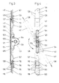
- the fitting shown in Figures 1 and 2 has two mounted in extension to each other Driving rods 1, 2, between which a gear 3 is available.
- the gear 3 consists of a housing 4 with a housing base 5 and two from the housing 4 striving in the opposite direction Gear locks 6, 7 and one housed in the housing 4 and via a nut 8 actuatable pinion, via which the transmission latches 6, 7 when the Nut 8 in the direction of the connecting line 38 of the drive rods 1, 2 are movable.
- Each of the gear bolts 6, 7 has its free End a tooth box 9 or 10 in the form of a U-shaped End section, the side legs inside are provided with teeth 11 and 12 respectively.
- the tooth boxes 9, 10 is the associated end of the drive rod 1 or 2 used, which has an external toothing with teeth 13 and 14, respectively, with the teeth 11 or 12 of the tooth box 9 or 10 to effect an axial power transmission are interlocked.
- the connecting rods 1 and 2 are on the outside of the fitting each covered with a faceplate 15 or 16, which extends parallel to the drive rod 1 or 2.
- a transmission faceplate according to the invention 17 shown On this side of the fitting is in Figure 1 also a transmission faceplate according to the invention 17 shown, which for mounting in the direction of the arrows 18 can be placed on the transmission 3.
- the Transmission cover rail with passage openings 19 or 20 provided by which screws, not shown can be passed through which, on the other hand, in FIG. 1 only indicated bores or through openings 21 or 22 can be screwed in.
- the transmission faceplate 17 On the one facing the transmission faceplate 17 Side is the gear base 5 with projections 23 and 24 provided, which with corresponding recesses 25 and 26 in the transmission faceplate 17 as Interact adjustment aid or locking. Finally, the transmission faceplate 17 instructs here both ends, to the faceplate 15 and 16 respectively the drive rods 1 and 2 facing teeth 27 and 28 on that with corresponding lateral recesses 29 and 30 in the faceplates 15 and 16 of the drive rods 1 and 2 work together as an axial anchor.
- the transmission faceplate 17 is in relation to the Gear 3 slightly concave, so that in the figure 2 shown assembled state of the transmission faceplate 17 their two ends with preload against the assigned ends of the faceplate 15 and press 16 and hold it down. A disengagement the connecting rods 1 and 2 from the tooth boxes 9 and 10 is prevented.
- the connecting rods 1 and 2 are with their ends close to the gearbox between the gear bolt 6 or 7 and the held down ends the faceplate 15 or 16 clamped.
- Gear 103 struts from its bottom 105 round pin 131, which through an elongated hole 132 is passed through the transmission cuff rail 117 and with an outer waistband 133 one around it Elongated hole 132 surrounds inner collar 134.
- the transmission faceplate 117 is around in this variant the round pin 131 relative to the connecting line 138 of the two drive rods 101 and 102 or face plates 115 and 116 pivotable in the direction of the double arrow 135 and by means of the bottom 105 of the transmission 103 strutting projections 123, 124, which with the slot 132 cooperate in a swivel position lockable, in which the gear cover rail 117 extends along the connecting line 138.
- the transmission faceplate is 117 in the direction of arrows 136 in the direction their longitudinal axis 137 slidable. Extends the transmission faceplate 117 along the connecting line 138 of the drive rods 101 and 102 or face plates 115 and 116, so the coupling points through Moving the gear cuff rail 117 in the direction of arrows 136 are exposed one after the other, as in Figure 4 can be seen.
- This pin 239 is by a corresponding one Passage opening 242 in the transmission faceplate 217 passable, which is oriented so that a passage of the pin when the gear cover rail is pivoted 217 is possible while the cantilevered sections 240, 241 reach behind the gear cover plate 217, if this is in the direction of the connecting line 238 of the drive rods 201 and 202 extends. Also at In this variant, the coupling points are swiveled the transmission faceplate 217 around the pin 239 exposed from this direction.
- the fitting according to the invention is the first again the gear 203 in the fitting groove Sash used, this with or take place without the fitted cover plate 217 can. If the gear cover 217 is already attached, this is how it works before engaging the drive rods 201 and 202 pivoted about the pin 239. Now can drive rods 201 and 202 with the gear locks 205 and 206 coupled and the fitting units be screwed to the casement. Finally the gear cover 217 is pivoted back, so that they are towards the connecting line 238 of the drive rods 201 and 202 extends.
Landscapes
- Engineering & Computer Science (AREA)
- Mechanical Engineering (AREA)
- Power-Operated Mechanisms For Wings (AREA)
- Window Of Vehicle (AREA)
- Securing Of Glass Panes Or The Like (AREA)
Description
- Figur 1
- eine Seitenansicht eines erfindungsgemäßen Beschlages mit noch nicht vor- bzw. montierter Getriebestulpschiene,
- Figur 2
- eine Draufsicht auf den Beschlag von Figur 1 mit montierter Getriebestulpschiene,
- Figur 3
- eine Seitenansicht einer Variante des erfindungsgemäßen Beschlages,
- Figur 4
- eine Draufsicht auf die Variante von Figur 3,
- Figur 5
- eine Seitenansicht einer weiteren Variante des erfindungsgemäßen Beschlages und
- Figur 6
- eine Draufsicht auf den Beschlag von Figur 5.
- 1, 101, 201
- Treibstange
- 2, 102, 202
- Treibstange
- 3, 103, 303
- Getriebe
- 4, 104, 204
- Gehäuse
- 5, 105, 205
- Getriebeboden.
- 6, 106, 206
- Getrieberiegel
- 7, 107, 207
- Getrieberiegel
- 8, 108, 208
- Nuß
- 9, 109, 209
- Zahnkästchen
- 10, 110, 210
- Zahnkästchen
- 11, 111, 211
- Zahn
- 12, 112, 212
- Zahn
- 13, 113, 213
- Zahn
- 14, 114, 214
- Zahn
- 15, 115, 215
- Treibstangen-Stulpschiene
- 16, 116, 216
- Treibstangen-Stulpschiene
- 17, 117, 217
- Getriebestulpschiene
- 18
- Pfeil
- 19
- Durchtrittsöffnung
- 20
- Durchtrittsöffnung
- 21
- Bohrung bsw. Durchtrittsöffnung
- 22
- Bohrung bsw. Durchtrittsöffnung
- 23, 123, 223
- Vorsprung
- 24,124, 224
- Vorsprung
- 25, 225
- Ausnehmung
- 26, 226
- Ausnehmung
- 27, 127, 227
- Zahn
- 28, 128, 228
- Zahn
- 29, 129, 229
- Seitliche Ausnehmung
- 30, 130, 230
- Seitliche Ausnehmung
- 131
- Stift
- 132
- Langloch
- 133
- Außenbund
- 134
- Innenbund
- 135
- Doppelpfeil
- 136
- Pfeil
- 137
- Längsachse
- 38, 138, 238
- Verbindungslinie
- 239
- Stift
- 240
- Abschnitt
- 241
- Abschnitt
- 242
- Durchtrittsöffnung
- 243
- Doppelpfeil
Claims (11)
- Beschlag für ein Fenster oder eine Tür mit mindestens zwei in Verlängerung zueinander montierbaren Treibstangen (1, 101, 201; 2, 102, 202) und einem zwischen den Treibstangen angeordneten Getriebe (3, 103, 203), welches mittels zweier beweglicher Riegel (6, 106, 206) mit den angrenzenden Treibstangenenden kuppelbar ist, sowie mit jeder der beidseits des Getriebes gelegenen Treibstangen und dem Getriebe zugeordneten Stulpschienen (15, 115, 215; 16, 116, 216; 17, 117, 217), wobei die beiden Enden der Getriebestulpschiene (17, 117, 217) die getriebeseitigen Enden der den Treibstangen (1, 101, 201; 2, 102, 202) zugeordneten Stulpschienen (15, 115, 215; 16, 116, 216) übergreifen und als Aushebesicherung für die Kupplung zwischen den Treibstangen (1, 101, 201; 2, 102, 202) und den Getrieberiegeln (6, 106, 206; 7, 107, 207) wirken,
dadurch gekennzeichnet, dass die Verankerung der Getriebestulpschiene (17, 117, 217) gegenüber dem Flügel in Montagerichtung (18) nur über eine Verankerung der Getriebestulpschiene auf dem Getriebe (3, 103, 203) bewirkt ist und dass die Getriebestulpschiene (17, 117, 217) zwischen ihren Verankerungsstellen (21, 22) auf dem Getriebe und ihren die Treibstangenstulpschienen (15, 115, 215; 16, 116, 216) übergreifenden Enden in sich gegen ein Ausheben widerstandsfähig ausgebildet ist. - Beschlag nach Anspruch 1,
dadurch gekennzeichnet, daß die beiden Enden der Getriebestulpschiene (17, 117, 217) in Richtung auf die gegenüberliegenden Enden der Treibstangen-Stulpschienen (15, 115, 215; 16, 116, 216) vorgespannt sind. - Beschlag nach Anspruch 2,
dadurch gekennzeichnet, daß die Getriebestulpschiene (17, 117, 217) zur Bewirkung der Vorspannung gewölbt ist oder gekröpfte Enden aufweist. - Beschlag nach einem der Ansprüche 1 bis 3,
dadurch gekennzeichnet, daß die Getriebestulpschiene (17) auf das Getriebe (3) aufklippsbar ist. - Beschlag nach einem der Ansprüche 1 bis 3,
dadurch gekennzeichnet, daß die Getriebestulpschiene (217) über einen Bajonettverschluß (239 bis 242) auf dem Getriebe (203) verankerbar ist. - Beschlag nach Anspruch 5,
dadurch gekennzeichnet, daß das Getriebe (203) einen nach außen weisenden Stift (239) mit zwei entgegengesetzt auskragenden Abschnitten (240, 241) aufweist, mit welchen der Stift (239) durch eine entsprechende Durchtrittsöffnung (242) in der Getriebestulpschiene (217) hindurchführbar ist, wenn die Getriebestulpschiene (217) gegenüber der Verbindungslinie (238) der beiden Treibstangen (201, 202) um eine zur Schienenfläche senkrechte Achse verschwenkt ist. - Beschlag nach einem der Ansprüche 1 bis 3,
dadurch gekennzeichnet, daß die Getriebestulpschiene (117) über mindestens einen einen Außenbund (133) aufweisenden vom Getriebeboden (105) abstrebenden Stift (131) am Getriebe (102) verankert ist, welcher durch eine Durchtrittsöffnung in der Getriebestulpschiene (117) hindurchgeführt ist und diese mit seinem Außenbund (133) hintergreift. - Beschlag nach Anspruch 7,
dadurch gekennzeichnet, daß die Getriebestulpschiene (117) um den Stift (131) gegenüber der Verbindungslinie (138) der beiden Treibstangen (101, 102) verschwenkbar ist. - Beschlag nach Anspruch 7 oder 8,
dadurch gekennzeichnet, daß der Stift (131) durch ein Langloch (132) der Getriebestulpschiene (117) hindurchgeführt ist und mit seinem Außenbund (132) einen umlaufenden Innenbund (134) des Langlochs (132) hintergreift, so daß die montierte Getriebestulpschiene (117) zwischen zwei Endstellungen längs der Verbindungslinie (138) der beiden Treibstangen (101, 102) relativ zum Getriebe (103) verschiebbar ist. - Beschlag nach einem der vorhergehenden Ansprüche,
dadurch gekennzeichnet, daß eine zwischen Getriebe (3, 103, 203) und Getriebestulpschiene (17, 117, 217) wirkende Schwenk-Arretierung (23, 123, 223; 24, 124, 224: 25, 125, 225: 26, 126, 226) vorhanden ist. - Beschlag nach einem der vorhergehenden Ansprüche,
dadurch gekennzeichnet, daß die Getriebestulpschiene (17, 117, 217) an beiden Enden Zähne (27, 127, 227: 28, 128, 228) aufweist, welche mit entsprechenden seitlichen Ausnehmungen (29, 129, 229: 30, 130, 230) in den Stulpschienen (15, 115, 215; 16, 116, 216) der Treibstangen (1, 101, 201; 2, 102, 202) als Verankerung zusammenwirken.
Applications Claiming Priority (2)
| Application Number | Priority Date | Filing Date | Title |
|---|---|---|---|
| DE9403801U | 1994-03-07 | ||
| DE9403801U DE9403801U1 (de) | 1994-03-07 | 1994-03-07 | Beschlag für ein Fenster oder eine Tür |
Publications (3)
| Publication Number | Publication Date |
|---|---|
| EP0671530A1 EP0671530A1 (de) | 1995-09-13 |
| EP0671530B1 EP0671530B1 (de) | 1998-09-09 |
| EP0671530B2 true EP0671530B2 (de) | 2003-04-23 |
Family
ID=6905592
Family Applications (1)
| Application Number | Title | Priority Date | Filing Date |
|---|---|---|---|
| EP95102021A Expired - Lifetime EP0671530B2 (de) | 1994-03-07 | 1995-02-14 | Beschlag für ein Fenster oder eine Türe |
Country Status (2)
| Country | Link |
|---|---|
| EP (1) | EP0671530B2 (de) |
| DE (2) | DE9403801U1 (de) |
Families Citing this family (8)
| Publication number | Priority date | Publication date | Assignee | Title |
|---|---|---|---|---|
| EP0740039B1 (de) * | 1995-04-28 | 1999-11-03 | Siegenia-Frank Kg | Verfahren zur Ausstattung eines Flügels mit einem Treibstangenbeschlag |
| DE19709492A1 (de) * | 1997-03-07 | 1998-09-24 | Hautau Gmbh W | Von Nutentiefen unabhängige Riegeleinrichtung für Flügel |
| DE19823607A1 (de) * | 1998-05-27 | 1999-12-02 | Winkhaus Fa August | Verbindungselement für Treibstangen von Rundbogenfenstern |
| DE19858843B4 (de) * | 1998-12-19 | 2007-10-25 | Aug. Winkhaus Gmbh & Co. Kg | Kantengetriebe für einen Fenster- oder Türbeschlag |
| FR2788545B1 (fr) * | 1999-01-18 | 2001-03-09 | Ferco Int Usine Ferrures | Ferrure de verrouillage du type serrure, cremone, cremone-serrure ou autre comportant une tetiere munie d'une plaque signalitique et/ou d'identification |
| DE602006009794D1 (de) * | 2006-07-19 | 2009-11-26 | Vita Mfg Co Ltd | Verriegelungseinrichtung für Fenster oder Tür |
| FR2953244B1 (fr) * | 2009-12-01 | 2012-09-28 | Map Massard | Boitier de commande d'une tringle de manoeuvre d'une cremone |
| CN112065180B (zh) * | 2020-09-28 | 2025-01-14 | 深圳好博窗控技术股份有限公司 | 一种驱动装置 |
Family Cites Families (12)
| Publication number | Priority date | Publication date | Assignee | Title |
|---|---|---|---|---|
| DE2313690C2 (de) * | 1973-03-20 | 1987-11-12 | Siegenia-Frank Kg, 5900 Siegen | Treibstangenbeschlag für Fenster, Türen od.dgl |
| DE2504420A1 (de) * | 1975-02-03 | 1976-08-05 | Fuhr C Fa | Treibstangenverschluss, insbesondere fuer fluegel von fenstern, tueren oder dergleichen |
| DE7603047U1 (de) * | 1976-02-04 | 1976-06-03 | Siegenia-Frank Kg, 5900 Siegen- Kaan-Marienborn | Ueberlappungsverbindung zwischen stulpschienen von treibstangenbeschlaegen |
| DE2658465C3 (de) * | 1976-12-23 | 1982-06-16 | Siegenia-Frank Kg, 5900 Siegen | Vorrichtung zum Befestigen der Stulpschienen von Treibstangenbeschlägen für Fenster und Türen aus Holz oder Kunststoff |
| DE7929165U1 (de) * | 1979-10-13 | 1980-01-17 | Siegenia-Frank Kg, 5900 Siegen | Vorrichtung zur stosstellenueberlappung an stulpschienen |
| FR2554496B1 (fr) * | 1983-11-07 | 1986-01-10 | Ferco Int Usine Ferrures | Cremone a larder pour ouvrant de fenetre, porte ou analogue |
| FR2585756A1 (fr) * | 1985-07-30 | 1987-02-06 | Massard Ets J | Dispositif de jonction entre boitier et prolongateur de cremone a tetiere et a tringles |
| DE3637317A1 (de) * | 1986-11-03 | 1988-05-11 | Siegenia Frank Kg | Ueberlappungsverbindung |
| DE8632641U1 (de) * | 1986-12-05 | 1987-02-19 | Mayer & Co., Salzburg | Vorrichtung zur Stulpschienenverbindung |
| IT1216597B (it) * | 1988-04-19 | 1990-03-08 | Ruffoni & Zoppi Srl | Chiusura a cremonese. |
| DE4014041A1 (de) * | 1990-05-02 | 1991-11-07 | Fuhr Carl Gmbh & Co | Schliesszylinderbetaetigbares treibstangenschloss |
| DE9212950U1 (de) * | 1992-09-25 | 1992-12-03 | Siegenia-Frank Kg, 5900 Siegen | Treibstangenbeschlag für Fenster, Türen o.dgl. |
-
1994
- 1994-03-07 DE DE9403801U patent/DE9403801U1/de not_active Expired - Lifetime
-
1995
- 1995-02-14 EP EP95102021A patent/EP0671530B2/de not_active Expired - Lifetime
- 1995-02-14 DE DE59503477T patent/DE59503477D1/de not_active Expired - Lifetime
Also Published As
| Publication number | Publication date |
|---|---|
| EP0671530B1 (de) | 1998-09-09 |
| EP0671530A1 (de) | 1995-09-13 |
| DE9403801U1 (de) | 1995-04-06 |
| DE59503477D1 (de) | 1998-10-15 |
Similar Documents
| Publication | Publication Date | Title |
|---|---|---|
| EP0526522B1 (de) | Mit zylinderschlosseinrichtung arretierbarer schwenkhebelverschluss | |
| EP1478528B1 (de) | Schwenkbare anhängevorrichtung für zugfahrzeuge | |
| DE60310000T2 (de) | Schlossanordnung für Sektionaltore | |
| DE8404254U1 (de) | Randschiene fuer eine scheibe, insbesondere einer ganzglastuere | |
| EP0671530B2 (de) | Beschlag für ein Fenster oder eine Türe | |
| DE19715055C2 (de) | Riegelzapfen | |
| DE8323365U1 (de) | Treibstangenbeschlag fuer fenster, tueren od. dgl. | |
| DE3718173C2 (de) | ||
| EP1407901B1 (de) | Anhängevorrichtung für Zugfahrzeuge | |
| EP2165033B1 (de) | Verschlussbolzen | |
| DE1065749B (de) | ||
| DE29613802U1 (de) | Einsteckgetriebe für die Betätigung von Treibstangenbeschlägen an Fenstern, Türen o.dgl. | |
| DE3604115A1 (de) | Tuerdrueckeranordnung | |
| EP0641908A2 (de) | Kabelschloss, insbesondere für Zweiradfahrzeuge | |
| EP1061215A2 (de) | Getriebeanordnung für einen Stangenverschluss | |
| DE19807050A1 (de) | Kraftübertragungsvorrichtung für die Betätigung eines Vorhangs | |
| DE19736934C2 (de) | Verriegelungsbeschlag | |
| EP0785329B1 (de) | Betätigungsgetriebe für einen Treibstangenbeschlag | |
| EP0677631B2 (de) | Betätigungsvorrichtung für ein Verschlussgetriebe | |
| EP1580370B1 (de) | Beschlaganordnung | |
| DE19748059C2 (de) | Treibstangenbeschlag für bewegliche Steuerelemente an einem Fenster oder einer Tür | |
| DE19832356C2 (de) | Kantenriegelbeschlag | |
| DE20215508U1 (de) | Anhängevorrichtung für Zugfahrzeuge | |
| EP2855810B1 (de) | Beschlagsystem für ein fenster, eine tür oder dergleichen | |
| DE3527559C2 (de) |
Legal Events
| Date | Code | Title | Description |
|---|---|---|---|
| PUAI | Public reference made under article 153(3) epc to a published international application that has entered the european phase |
Free format text: ORIGINAL CODE: 0009012 |
|
| AK | Designated contracting states |
Kind code of ref document: A1 Designated state(s): DE GB IT |
|
| 17P | Request for examination filed |
Effective date: 19960307 |
|
| GRAG | Despatch of communication of intention to grant |
Free format text: ORIGINAL CODE: EPIDOS AGRA |
|
| 17Q | First examination report despatched |
Effective date: 19971030 |
|
| GRAG | Despatch of communication of intention to grant |
Free format text: ORIGINAL CODE: EPIDOS AGRA |
|
| GRAH | Despatch of communication of intention to grant a patent |
Free format text: ORIGINAL CODE: EPIDOS IGRA |
|
| GRAH | Despatch of communication of intention to grant a patent |
Free format text: ORIGINAL CODE: EPIDOS IGRA |
|
| GRAA | (expected) grant |
Free format text: ORIGINAL CODE: 0009210 |
|
| ITF | It: translation for a ep patent filed | ||
| AK | Designated contracting states |
Kind code of ref document: B1 Designated state(s): DE GB IT |
|
| REF | Corresponds to: |
Ref document number: 59503477 Country of ref document: DE Date of ref document: 19981015 |
|
| GBT | Gb: translation of ep patent filed (gb section 77(6)(a)/1977) |
Effective date: 19981026 |
|
| PLBI | Opposition filed |
Free format text: ORIGINAL CODE: 0009260 |
|
| PLBF | Reply of patent proprietor to notice(s) of opposition |
Free format text: ORIGINAL CODE: EPIDOS OBSO |
|
| 26 | Opposition filed |
Opponent name: SIEGENIA-FRANK KG Effective date: 19990602 |
|
| PLBF | Reply of patent proprietor to notice(s) of opposition |
Free format text: ORIGINAL CODE: EPIDOS OBSO |
|
| REG | Reference to a national code |
Ref country code: GB Ref legal event code: IF02 |
|
| PLAW | Interlocutory decision in opposition |
Free format text: ORIGINAL CODE: EPIDOS IDOP |
|
| PLAW | Interlocutory decision in opposition |
Free format text: ORIGINAL CODE: EPIDOS IDOP |
|
| PUAH | Patent maintained in amended form |
Free format text: ORIGINAL CODE: 0009272 |
|
| STAA | Information on the status of an ep patent application or granted ep patent |
Free format text: STATUS: PATENT MAINTAINED AS AMENDED |
|
| 27A | Patent maintained in amended form |
Effective date: 20030423 |
|
| AK | Designated contracting states |
Designated state(s): DE GB IT |
|
| GBTA | Gb: translation of amended ep patent filed (gb section 77(6)(b)/1977) | ||
| EN | Fr: translation not filed | ||
| REG | Reference to a national code |
Ref country code: GB Ref legal event code: 732E Free format text: REGISTERED BETWEEN 20100415 AND 20100421 |
|
| REG | Reference to a national code |
Ref country code: DE Ref legal event code: R082 Ref document number: 59503477 Country of ref document: DE Representative=s name: MANITZ, FINSTERWALD & PARTNER GBR, DE Effective date: 20120126 Ref country code: DE Ref legal event code: R081 Ref document number: 59503477 Country of ref document: DE Owner name: MACO TECHNOLOGIE GMBH, AT Free format text: FORMER OWNER: MACO VERMOEGENSVERWALTUNG GMBH, SALZBURG, AT Effective date: 20120126 |
|
| REG | Reference to a national code |
Ref country code: GB Ref legal event code: 732E Free format text: REGISTERED BETWEEN 20120412 AND 20120418 |
|
| PGFP | Annual fee paid to national office [announced via postgrant information from national office to epo] |
Ref country code: IT Payment date: 20140227 Year of fee payment: 20 |
|
| PGFP | Annual fee paid to national office [announced via postgrant information from national office to epo] |
Ref country code: GB Payment date: 20140218 Year of fee payment: 20 |
|
| PGFP | Annual fee paid to national office [announced via postgrant information from national office to epo] |
Ref country code: DE Payment date: 20140429 Year of fee payment: 20 |
|
| REG | Reference to a national code |
Ref country code: DE Ref legal event code: R071 Ref document number: 59503477 Country of ref document: DE |
|
| REG | Reference to a national code |
Ref country code: GB Ref legal event code: PE20 Expiry date: 20150213 |
|
| PG25 | Lapsed in a contracting state [announced via postgrant information from national office to epo] |
Ref country code: GB Free format text: LAPSE BECAUSE OF EXPIRATION OF PROTECTION Effective date: 20150213 |