EP0670083B1 - Stecker - Google Patents
Stecker Download PDFInfo
- Publication number
- EP0670083B1 EP0670083B1 EP94900774A EP94900774A EP0670083B1 EP 0670083 B1 EP0670083 B1 EP 0670083B1 EP 94900774 A EP94900774 A EP 94900774A EP 94900774 A EP94900774 A EP 94900774A EP 0670083 B1 EP0670083 B1 EP 0670083B1
- Authority
- EP
- European Patent Office
- Prior art keywords
- outer part
- inner part
- plug
- channels
- wire ends
- Prior art date
- Legal status (The legal status is an assumption and is not a legal conclusion. Google has not performed a legal analysis and makes no representation as to the accuracy of the status listed.)
- Expired - Lifetime
Links
Images


Classifications
-
- H—ELECTRICITY
- H01—ELECTRIC ELEMENTS
- H01R—ELECTRICALLY-CONDUCTIVE CONNECTIONS; STRUCTURAL ASSOCIATIONS OF A PLURALITY OF MUTUALLY-INSULATED ELECTRICAL CONNECTING ELEMENTS; COUPLING DEVICES; CURRENT COLLECTORS
- H01R24/00—Two-part coupling devices, or either of their cooperating parts, characterised by their overall structure
- H01R24/60—Contacts spaced along planar side wall transverse to longitudinal axis of engagement
- H01R24/62—Sliding engagements with one side only, e.g. modular jack coupling devices
- H01R24/64—Sliding engagements with one side only, e.g. modular jack coupling devices for high frequency, e.g. RJ 45
-
- H—ELECTRICITY
- H01—ELECTRIC ELEMENTS
- H01R—ELECTRICALLY-CONDUCTIVE CONNECTIONS; STRUCTURAL ASSOCIATIONS OF A PLURALITY OF MUTUALLY-INSULATED ELECTRICAL CONNECTING ELEMENTS; COUPLING DEVICES; CURRENT COLLECTORS
- H01R4/00—Electrically-conductive connections between two or more conductive members in direct contact, i.e. touching one another; Means for effecting or maintaining such contact; Electrically-conductive connections having two or more spaced connecting locations for conductors and using contact members penetrating insulation
- H01R4/24—Connections using contact members penetrating or cutting insulation or cable strands
- H01R4/2404—Connections using contact members penetrating or cutting insulation or cable strands the contact members having teeth, prongs, pins or needles penetrating the insulation
Definitions
- the invention relates to a plug for electrical connection with a plurality of insulated wire ends, comprising a prism-like housing which has a flat side aligned parallel to the plugging direction and which consists of an inner part and an outer part, the inner part in the outer part in the manner of a drawer in the direction of the Insertable direction, which outer part has a plurality of transverse slots in the front area in the plug-in direction from the flat side, which inner part contains a bottom side facing the flat side and a plurality of closely adjacent channels, which are at least approximately parallel to one another and to the flat side, for wire ends which can be inserted therein
- Inner part has a front end face in the direction of insertion and a rear end face arranged at a distance therefrom, as well as two side faces opposite one another and projecting transversely to the bottom side, the distance between the end faces Achen is smaller than the length of the outer part seen in the direction of insertion, each cross slot of the outer part being aligned with one of the channels if the inner part is
- the inner part is known as the WESTERN plug (because it was first marketed by the company WESTERNELECTRIC.)
- WESTERNELECTRIC The particular advantage of this plug is that the wire ends and their insulation can be inserted into the channels.
- the contact blades which are of course still withdrawn from the channels, are then pressed into the wire ends fixed in the channels with a simple pressing tool. They cut through the insulation and make contact with the copper souls.
- the contact lamellae form the contacts of the plug with their edge surfaces which are approximately flush with the flat side.
- the wire ends In order for the contact between the contact lamella and the copper core to be reliable, the wire ends must be held in the channels with as little play as possible.
- the object of the invention is to provide a connector of the generic type which avoids assembly errors and in which there is the possibility of providing a larger variation in usable wire diameters.
- the inner part in the front portion in the plug-in direction has cross-slit portions pointing to the bottom side, each of which is aligned with a transverse slit of the outer part when the inner part is arranged in the outer part in that two narrow webs protrude from the rear end face and extend backwards. whose outer sides are each aligned with the side surfaces and that locking cams are formed on the webs, which can be snapped into corresponding locking recesses in the outer part in the inserted state.
- the inner part is supported to a greater length in the outer part despite its reduced length, because these webs are guided in it over the remaining length of the outer part.
- the length of the webs is fixed in such a way that their rear ends lie outside the outer part when the inner part is arranged in the outer part. In order to you can release the lock if necessary without special tools. You can also quickly see the exact insertion position.
- the plug is very flat if the center axes of adjacent channels are arranged in a common plane that is parallel to the flat side.
- the maximum permissible wire diameter is then limited by the available width of the inner part and the number of wire ends to be distributed on it.
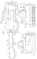
- the plug consists of an outer part 15 of generally prismatic shape and a flat, likewise prismatic inner part 16.
- the outer part has a front wall 18 in the insertion direction according to arrow 17, and a rear wall 19 opposite in parallel.
- a spring clip 25 stands up from the top wall 23 and serves to lock the plug in a socket (not particularly shown here).
- the lower wall 24 is stepped in the side view of FIG. 1, so that a wall section 26 extends from the rear wall 19 and lies lower than a flat side 27 which adjoins the front wall 18.
- the rear and middle part of the outer part is covered by a metal shield 28.
- the outer shape of the outer part 15 corresponds to that of a commercially available WESTERN plug, at least essentially and therefore does not need to be explained in more detail.
- a chamber 29 open to the rear wall 19, the shape of which can best be seen from FIGS. 3 and 4.
- the chamber is also approximately prismatic and is divided into a front part 32 and a rear, further part 32, which is intended to receive a cable end with its shield exposed there and to fix it in a known manner.
- the front part 31 has a lower inner wall 33 which is aligned parallel to the flat side 27.
- the inner part 16 corresponds in its dimensions and shape to the front part 31 of the chamber 29 and can be moved from the rear wall 19 in a direction parallel to the flat side 27 in the manner of a drawer insert this part 31 with little play.
- the inner part 16 has a front end face 34 and a rear, stepped end face 35, the distance between them corresponding to approximately half the length of the outer part.
- it has two opposite parallel side surfaces 36 and 37, as well as a bottom side 40, which in the inserted state rests on the lower inner wall 33 of the front part 31 of the chamber 29.
- FIGS. 5 to 8 clearly show, two lateral narrow webs 38 and 39 protrude rearward from the rear end face 35, the outer sides of which are in each case flush with the side faces 36, 37.
- the height of the webs 38, 39 in the side view according to FIG. 1 or 6 corresponds to the height of the rear part 32 of the chamber 29, so that the webs are guided therein with little play and offer the inner part 16 an additional support.
- downwardly projecting locking cams 42 are also formed, which engage in correspondingly designed locking recesses 43 (FIG. 4) in the rear part 32 of the chamber 29 when the inner part 16 is fully inserted into the chamber 29 of the outer part is.
- the length of the webs 38, 39 is dimensioned so that their rear ends 44 are still a few millimeters outside of the outer part 15.
- the inner part 16 contains a predetermined number (usually eight) of channels 45 which are parallel to one another.
- the center axes of the channels 45 extend at least approximately parallel to the bottom side 40 and lie in a common plane 46 parallel to them
- a transverse slot section 47 opens out from each channel 45 and aligns with a transverse slot 48 (FIGS. 2 and 4) arranged in a corresponding position in the outer part 15.
- the transverse slots 48 each have a plate-like shape Contact lamella 49 exactly in the manner of the known connector too.
- the channels 45 and transverse slot sections 47 are formed continuously up to the front end face 34, which enables a cheaper injection molding tool.
- a cable 51 is indicated with dashed lines in FIG. 8, the exposed shield 52 of which lies in the space between the webs 38, 39.
- the wire ends 53 emerging from the sheathed shield 52 have insulating jackets which are marked in different colors and it is the task of the installer to insert certain wire ends into respective channels 45.
- a color mark 54 can be applied to the bottom side 40 of each channel. For example in the form of an embossed letter code.
- the fanned-out wire ends 53 are inserted into the channels 45 with the outer part 15 removed, so that the position of the channels 45 can be seen clearly.
- the outer part 15 is pushed over the inner part 16 until the locking cams 42 snap into the locking recesses 43.
- the cable end with the exposed shield 52 is pressed into the rear part 32 of the chamber 29 and metal parts of the metal shield 28 protruding from there are contacted.
- the contact blades 49 are then pressed into the channels 45 by means of a pliers-like tool, so that they cut through the insulation of the wire ends 53 and contact the wires in each case. Their outer edge surfaces 55 then form the contacts of the plug.
- inner parts 16 with channels 45 of different widths are used. Since the transverse distance between the contact blades 49 is fixed, different thicknesses remain between the channels 45 Partition walls are available, depending on the cross-sectional diameter of the channels. The upper diameter limit is reached when the partitions are reduced to sectors and the wire ends are practically directly adjacent to each other. A further increase in the wire diameter is then possible in the case of channels 56 and 57, which are alternately offset in terms of height, as shown in FIG. 9.
- the channels 56 lie in a common plane 58 and the channels 57 in another common plane 59, which is closer to the bottom side 40.
- the center axes of adjacent channels 56 and 57 are thus arranged in two different planes 58, 59, each parallel to the bottom side 40 (and thus ultimately to the flat side 27).
Landscapes
- Details Of Connecting Devices For Male And Female Coupling (AREA)
- Taps Or Cocks (AREA)
- Multi-Conductor Connections (AREA)
- Coupling Device And Connection With Printed Circuit (AREA)
- Connector Housings Or Holding Contact Members (AREA)
- Connections By Means Of Piercing Elements, Nuts, Or Screws (AREA)
- Indole Compounds (AREA)
Description
- Die Erfindung betrifft einen Stecker zur elektrischen Verbindung mit einer Mehrzahl isolierter Drahtenden, umfassend ein prismenähnliches Gehäuse, das eine parallel zur Steckrichtung ausgerichtete Flachseite aufweist und das aus einem Innenteil und einem Außenteil besteht, wobei der Innenteil in den Außenteil nach Art einer Schublade in Richtung der Steckrichtung einschiebbar ist, welcher Außenteil im in Steckrichtung vorderen Bereich von der Flachseite ausgehend eine Mehrzahl von Querschlitzen aufweist, welcher Innenteil eine zur Flachseite weisende Bodenseite und eine Mehrzahl eng nebeneinander liegender, zueinander und zur Flachseite wenigstens annähernd paralleler Kanäle für darin einsteckbare Drahtenden enthält, welcher Innenteil eine in Steckrichtung vordere Stirnfläche und eine mit Abstand dazu angeordnete rückwärtige Stirnfläche, sowie zwei einander gegenüberliegende und quer zur Bodenseite abstehende Seitenflächen aufweist, wobei der Abstand zwischen den Stirnflächen kleiner ist, als die Länge des Außenteiles in Steckrichtung gesehen, wobei jeder Querschlitz des Außenteiles jeweils mit einem der Kanäle fluchtet, wenn der Innenteil im Außenteil angeordnet ist und wobei in jedem Querschlitz eine plättchenförmige Kontaktlamelle einsetzbar ist, die mit dem Drahtende in dem damit fluchtenden Kanal in elektrische Verbindung bringbar ist.
- Ein Stecker von prinzipiell ähnlicher Art, bei dem aber kein separates Innenteil vorhanden ist, ist als WESTERN-Stecker bekannt (weil von der Firma WESTERNELECTRIC erstmals in den Handel gebracht.) Der besondere Vorteil dieses Steckers besteht darin, daß die Drahtenden mit samt ihrer Isolierung in die Kanäle eingesteckt werden können. Die kontaktlamellen, die dabei natürlich noch aus den Kanälen zurückgezogen sind, werden sodann mit einem einfachen Preßwerkzeug in die in den Kanälen fixierten Drahtenden hineingedrückt. Sie schneiden dabei durch die Isolierungen und legen sich kontaktierend an die Kupferseelen. Zugleich bilden die Kontaktlamellen mit ihren etwa mit der Flachseite fluchtenden Randflächen die Kontakte des Steckers. Damit die Kontaktierung zwischen den Kontaktlamellen und den Kupferseelen zuverlässig erfolgt, müssen die Drahtenden mit möglichst wenig Spiel in den Kanälen gehalten werden.
- Ein demgegenüber weiterentwickelter, gattungsgemäßer Stecker ist in der EP-A- 0 175 868 beschrieben. Der Innenteil wird "load block" genannt. Die Drahtenden können in den separierten Innenteil eingesteckt werden, wodurch sie übersichtlich richtig sortiert und positioniert werden. Danach wird der Innenteil mit den Drahtenden in den Außenteil eingeschoben, woraufhin die Kontaktlamellen eingepreßt werden. Dabei müssen die Kontaktlamellen auf einen Wandbereich des Innenteiles durchstoßen.
- Aufgabe der Erfindung ist es, einen Stecker der gattungsgemäßen Art zu schaffen, der Montagefehler vermeidet und bei dem die Möglichkeit besteht, eine größere Variation an verwendbaren Drahtdurchmessern vorzusehen.
- Diese Aufgabe wird dadurch gelöst, daß der Innenteil im in Steckrichtung vorderen Teilbereich zur Bodenseite hinweisende Querschlitzabschnitte aufweist, die jeweils mit einem Querschlitz des Außenteils fluchten, wenn der Innentel im Außenteil angeordnet ist, daß von der rückwärtigen Stirnfläche zwei schmale Stege nach rückwärts reichend abstehen, deren Außenseiten jeweils mit den Seitenflächen fluchten und daß an den Stegen Rastnocken angeformt sind, die in korrespondierende Rastvertiefungen des Außenteiles im eingeschobenen Zustand einrastbar sind.
- Zufolge der Stege wird der Innenteil trotz seiner reduzierten Länge auf eine größere Länge hin im Außenteil abgestützt, denn diese Stege sind über die restliche Länge des Außenteiles darin geführt.
- Besonders vorteilhaft ist dabei, wenn die Länge der Stege derart festgelegt ist, daß deren rückwärtige Enden außerhalb des Außenteiles liegen, wenn der Innenteil im Außenteil angeordnet ist. Damit kann man gegebenenfalls ohne besonderes Werkzeug die Arretierung lösen. Auch kann man dadurch die exakte Einschiebeposition rasch erkennen.
- Wenn weiterhin die Querschlitzabschnitte bis zur vorderen Stirnfläche reichen vereinfacht dies den Herstellvorgang und das Formwerkzeug.
- Der Stecker ist sehr flach, wenn die Mittenachsen benachbarter Kanäle in einer gemeinsamen Ebene angeordnet sind, die zur Flachseite parallel liegt. Allerdings ist dann der maximal zulässige drahtdurchmesser durch die verfügbare Breite des Innenteiles und die Anzahl der darauf zu verteilenden Drahtenden begrenzt.
- Wenn daher die Mittenachsen benachbarter Kanäle in zwei verschiedenen, jeweils zur Flachseite parallelen Ebenen angeordnet sind, kann man eine gleiche Anzahl erheblich dickerer Drahtenden unterbringen.
- Die Erfindung wird nachfolgend anhand eines in der Zeichnung dargestellten bevorzugten Ausführungsbeispiels näher erläutert.
- Es zeigt:
- Fig. 1 eine Seitenansicht auf den Außenteil und Innenteil im getrennten Zustand,
- Fig. 2 eine Frontansicht des Außenteiles in Pfeilrichtung 2 von Fig.1,
- Fig. 3 eine Rückansicht des Außenteiles in Pfeilrichtung 3 von Fig.1,
- Fig. 4 einen Schnitt durch den Außenteil gemäß der Schnittebene 4-4 in Fig.2,
- Fig. 5 eine Frontansicht des Innenteiles in Pfeilrichtung 5 von Fig.1,
- Fig. 6 einen Schnitt durch den Innenteil gemäß der Schnittebene 6-6 in Fig.5,
- Fig. 7 einen Schnitt in der Ebene 7-7 von Fig.6, teilweise abgebrochen,
- Fig. 8 eine Unteransicht des Innenteiles in Pfeilrichtung 8 in Fig. 1
- Fig. 9 eine der Fig.5 entsprechende Frontansicht gemäß einer Variante in teilweise abgebrochener Darstellung.
- Wie die Figuren 1 bis 3 erkennen lassen, besteht der Stecker aus einem Außenteil 15 von allgemein prismatischer Gestalt und einem flachen, ebenso prismatischen Innenteil 16. Der Außenteil hat in der Einsteckrichtung gemäß dem Pfeil 17 vorneliegend eine Vorderwand 18, parallel gegenüberliegend eine Rückwand 19, zwei zueinander parallele Seitenwände 21, 22, eine Deckwand 23 und eine dazu parallele Unterwand 24. Von der Deckwand 23 steht ein Federbügel 25 hoch, der dazu dient, den Stecker in einer (hier nicht besonders dargestellten) Buchse zu arretieren. Die Unterwand 24 ist in der Seitenansicht der Fig.1 stufenartig abgesetzt, so daß von der Rückwand 19 ein Wandabschnitt 26 ausgeht, der gegenüber einer Flachseite 27, die an die Vorderwand 18 anschließt, tiefer liegt. Der rückwärtige und mittlere Teil des Außenteiles ist von einer Metallabschirmung 28 umhüllt. Die äußere Gestalt des Außenteiles 15 entspricht der eines handelsüblichen WESTERN-Steckers, jedenfalls im Wesentlichen und braucht daher nicht näher erläutert zu werden.
- Im Inneren des Außenteiles 15 ist eine zur Rückwand 19 offene Kammer 29 ausgespart, deren Gestalt aus den Figuren 3 und 4 am besten ersichtlich ist. Die Kammer ist ebenfalls etwa prismatisch und gliedert sich in einen vorderen Teil 32 und einen rückwärtigen, weiteren Teil 32, der dazu bestimmt ist, ein Kabelende mit dessen dort freiliegender Abschirmung aufzunehmen und in bekannter Weise zu fixieren. Der vordere Teil 31 hat eine untere Innenwand 33, die parallel zur Flachseite 27 ausgerichtet ist.
- Der Innenteil 16 entspricht in seinen Abmessungen und seiner Form dem vorderen Teil 31 der Kammer 29 und läßt sich von der Rückwand 19 her in einer zur Flachseite 27 parallelen Richtung nach der Art einer Schublade mit geringem Spiel in diesen Teil 31 einschieben. Insoweit hat der Innenteil 16 eine vordere Stirnfläche 34 und eine rückwärtige, stufenförmig abgesetzte Stirnfläche 35, wobei der Abstand dazwischen etwa der halben Länge des Außenteiles entspricht. Weiterhin hat er zwei gegenüberliegende parallele Seitenflächen 36 und 37, sowie eine Bodenseite 40, die im eingeschobenen Zustand auf der unteren Innenwand 33 des vorderen Teils 31 der Kammer 29 anliegt.
- Wie die Figuren 5 bis 8 deutlich zeigen, stehen von der rückwärtigen Stirnfläche 35 zwei seitliche schmale Stege 38 und 39 nach rückwärts ab, deren Außenseiten jeweils mit den Seitenflächen 36, 37 fluchten. Die Höhe der Stege 38, 39 in der Seitenansicht nach Fig.1 oder 6 entspricht der Höhe des rückwärtigen Teils 32 der Kammer 29, so daß die Stege darin mit wenig Spiel geführt sind und dem Innenteil 16 eine zusätzliche Stütze bieten. An den Unterkanten 41 der Stege 38, 39 sind außerdem nach unten vorspringende Rastnocken 42 ausgebildet, die in korrespondierend gestaltete Rastvertiefungen 43 (Fig.4) im rückwärtigen Teil 32 der Kammer 29 einrasten, wenn der Innenteil 16 in die Kammer 29 des Außenteiles voll eingeschoben ist. Die Länge der Stege 38, 39 ist dabei so bemessen, daß deren rückwärtige Enden 44 noch einige Millimeter außerhalb des Außenteiles 15 liegen.
- Der Innenteil 16 enthält, wie die Figuren 5 und 6 zeigen, eine vorgegebene Anzahl (meist acht) von zueinander parallelen Kanälen 45. Die Mittenachsen der Kanäle 45 erstrecken sich wenigstens annähernd parallel zur Bodenseite 40 und liegen in einer dazu parallelen gemeinsamen Ebene 46. Im vorderen Teilbereich geht von jedem Kanal 45 ein zur Bodenseite 40 ausmündender Querschlitzabschnitt 47 aus, der mit einem in einer korrespondierenden Lage im Außenteil 15 angeordneten Querschlitz 48 (Fig.2 und 4) fluchtet. Somit existiert eine der Anzahl von Kanälen 45 im Innenteil 16 gleiche Anzahl von Querschlitzen 48 im Außenteil 15. Die Querschlitze 48 führen jeweils eine plättchenförmige Kontaktlamelle 49 genau in der Art des bekannten Steckers auch.
- Im Ausführungsbeispiel sind die Kanäle 45 und Querschlitzabschnitte 47 bis zur vorderen Stirnfläche 34 durchgehend ausgebildet, was ein günstigeres Spritzgußwerkzeug ermöglicht.
- In der Fig.8 ist mit strichlierten Linien ein Kabel 51 angedeutet, dessen bloßgelegte Abschirmung 52 im Raum zwischen den Stegen 38, 39 liegt. Die aus der ummantelnden Abschirmung 52 austretenden Drahtenden 53 haben verschiedenfarbig markierte Isoliermäntel und es ist die Aufgabe des Monteurs, bestimmte Drahtenden in jeweils bestimmte Kanäle 45 einzustecken. Um dabei Irrtümer zu vermeiden, kann an der Bodenseite 40 bei jedem Kanal eine Farbmarke 54 angebracht werden. Etwa in Form eines eingeprägten Buchstabenkodes. Das Einstecken der aufgefächerten Drahtenden 53 in die Kanäle 45 geschieht bei abgenommenem Außenteil 15, so daß die Lage der Kanäle 45 gut erkennbar ist.
- Sobald die Drahtenden 53 in den Kanälen 45 stecken, wird der Außenteil 15 über den Innenteil 16 geschoben, bis die Rastnocken 42 in die Rastvertiefungen 43 einrasten. Dabei wird das Kabelende mit der freiliegenden Abschirmung 52 in den rückwärtigen Teil 32 der Kammer 29 gedrückt und von dort hineinragenden Metallteilen der Metallabschirmung 28 kontaktiert. Sodann werden die Kontaktlamellen 49 mittels eines zangenähnlichen Werkzeugs in die Kanäle 45 hinein gedrückt, so daß sie durch die Isolierungen der Drahtenden 53 schneiden und die Drähte jeweils kontaktieren. Ihre äußeren Randflächen 55 bilden dann die Kontakte des Steckers.
- Je nach dem Durchmesser der anzuschließenden Drahtenden 53 kommen Innenteile 16 mit entsprechend unterschiedlich weiten Kanälen 45 zur Anwendung. Da der Querabstand zwischen den Kontaktlamellen 49 festgelegt ist, bleiben zwischen den Kanälen 45 unterschiedlich dicke Trennwände stehen, abhängig vom Querschnittsdurchmesserder Kanäle. Die Durchmesserobergrenze ist dann erreicht, wenn die Trennwände zu Sektoren reduziert sind und die Drahtenden praktisch unmittelbar aneinander liegen. Eine weitere Vergrößerung des Drahtdurchmessers ist dann bei höhenmäßig abwechselnd versetzten Kanälen 56 und 57 gemäß Fig. 9 möglich. Hierbei liegen die Kanäle 56 in einer gemeinsamen Ebene 58 und die Kanäle 57 in einer anderen gemeinsamen Ebene 59, die sich näher zur Bodenseite 40 befindet. Somit sind die Mittenachsen benachbarter Kanäle 56 und 57 in zwei verschiedenen, jeweils zur Bodenseite 40 (und damit letztlich zur Flachseite 27) parallelen Ebenen 58, 59 angeordnet.
Claims (5)
- Stecker zur elektrischen Verbindung mit einer Mehrzahl isolierter Drahtenden (53),umfassend ein prismenähnliches Gehäuse, das eine parallel zur Steckrichtung (17) ausgerichtete Flachseite (27) aufweist und das aus einem Innenteil (16) und einem Außenteil (15) besteht, wobei der Innenteil (16) in den Außenteil (15) nach Art einer Schublade in Richtung der Steckrichtung (17) einschiebbar ist,welcher Außenteil (15) im in Steckrichtung (17) vorderen Bereich von der Flachseite (27) ausgehend eine Mehrzahl von Querschlitzen (48) aufweist,welcher Innenteil (16) eine zur Flachseite (27) weisende Bodenseite (40) und eine Mehrzahl eng nebeneinander liegender, zueinander und zur Flachseite (27) wenigstens annähernd paralleler Kanäle (45) für darin einsteckbare Drahtenden (53) enthält,welcher Innenteil (16) eine in Steckrichtung (17) vordere Stirnfläche (34) und eine mit Abstand dazu angeordnete rückwärtige Stirnfläche (35), sowie zwei einander gegenüberliegende und quer zur Bodenseite (40) abstehende Seitenflächen (36, 37) aufweist, wobei der Abstand zwischen den Stirnflächen (34, 35) kleiner ist, als die Länge des Außenteiles (15) in Steckrichtung gesehen, wobei jeder Querschlitz (48) des Außenteiles (15) jeweils mit einem der Kanäle (45) fluchtet, wenn der Innenteil (16) im Außenteil (15) angeordnet istund wobei in jedem Querschlitz (48) eine plättchenförmige Kontaktlamelle (49) einsetzbar ist, die mit dem Drahtende (53) in dem damit fluchtenden Kanal (45) in elektrische Verbindung bringbar ist,dadurch gekennzeichnet, daß der Innenteil (16) im in Steckrichtung (17) vorderen Teilbereich zur Bodenseite (40) hinweisende Querschlitzabschnitte (47) aufweist, die jeweils mit einem Querschlitz (48) des Außenteils (15) fluchten, wenn der Innenteil (16) im Außenteil (15) angeordnet ist, daß von der rückwärtigen Stirnfläche (35) zwei schmale Stege (38, 39) nach rückwärts reichend abstehen, deren Außenseiten jeweils mit den Seitenflächen (36, 37) fluchten und die im eingeschobenen Zustand über die restliche Länge des Außenteils darin geführt sind, und daß an den Stegen (38, 39) Rastnocken (42) angeformt sind, die in korrespondierende Rastvertiefungen (43) des Außenteiles (15) im eingeschobenen Zustand einrastbar sind.
- Stecker nach Anspruch 1, dadurch gekennzeichnet, daß die Länge der Stege (38, 39) derart festgelegt ist, daß deren rückwärtige Enden (44) außerhalb des Außenteiles (15) liegen, wenn der Innenteil (16) im Außenteil (15) angeordnet ist.
- Stecker nach Anspruch 1, dadurch gekennzeichnet, daß die Querschlitzabschnitte (47) bis zur vorderen Stirnfläche (34) des Innenteiles (16) reichen.
- Stecker nach Anspruch 1, dadurch gekennzeichnet, daß die Mittenachsen benachbarter Kanäle (45) in einer gemeinsamen Ebene (46) angeordnet sind, die zur Flachseite (27) parallel liegt.
- Stecker nach Anspruch 1, dadurch gekennzeichnet, daß die Mittenachsen benachbarter Kanäle (56, 57) in zwei verschiedenen, jeweils zur Flachseite (27) parallelen Ebenen (58, 59) angeordnet sind.
Applications Claiming Priority (3)
| Application Number | Priority Date | Filing Date | Title |
|---|---|---|---|
| DE4238923A DE4238923C2 (de) | 1992-11-19 | 1992-11-19 | Stecker |
| DE4238923 | 1992-11-19 | ||
| PCT/DK1993/000377 WO1994011927A1 (de) | 1992-11-19 | 1993-11-17 | Stecker |
Publications (2)
| Publication Number | Publication Date |
|---|---|
| EP0670083A1 EP0670083A1 (de) | 1995-09-06 |
| EP0670083B1 true EP0670083B1 (de) | 1997-01-15 |
Family
ID=6473188
Family Applications (1)
| Application Number | Title | Priority Date | Filing Date |
|---|---|---|---|
| EP94900774A Expired - Lifetime EP0670083B1 (de) | 1992-11-19 | 1993-11-17 | Stecker |
Country Status (14)
| Country | Link |
|---|---|
| EP (1) | EP0670083B1 (de) |
| JP (1) | JPH08505979A (de) |
| AT (1) | ATE147896T1 (de) |
| AU (1) | AU5560894A (de) |
| CZ (1) | CZ128495A3 (de) |
| DE (2) | DE4238923C2 (de) |
| DK (1) | DK0670083T3 (de) |
| FI (1) | FI952428L (de) |
| HU (1) | HUT76454A (de) |
| PL (1) | PL172992B1 (de) |
| RU (1) | RU95112564A (de) |
| SK (1) | SK65295A3 (de) |
| TW (1) | TW374264B (de) |
| WO (1) | WO1994011927A1 (de) |
Families Citing this family (5)
| Publication number | Priority date | Publication date | Assignee | Title |
|---|---|---|---|---|
| US5593314A (en) * | 1995-01-31 | 1997-01-14 | The Whitaker Corporation | Staggered terminal array for mod plug |
| US5628647A (en) | 1995-02-22 | 1997-05-13 | Stewart Connector Systems, Inc. | High frequency modular plug and cable assembly |
| US5727962A (en) * | 1995-09-29 | 1998-03-17 | Caveney; Jack E. | Modular plug connector |
| JP3136263B2 (ja) | 1996-01-25 | 2001-02-19 | ヒロセ電機株式会社 | モジュラープラグ用ガイドプレート |
| EP0932225A1 (de) * | 1998-01-26 | 1999-07-28 | Fridolin Alois Frech | Marhpoliger Stecker |
Family Cites Families (11)
| Publication number | Priority date | Publication date | Assignee | Title |
|---|---|---|---|---|
| IT1081631B (it) * | 1976-08-13 | 1985-05-21 | Amp Inc | Connettore elettrico |
| DE3203651A1 (de) * | 1982-02-03 | 1983-08-18 | Maigler, geb. Maigler, Brigitta, 7100 Heilbronn | Steckverbinder und verbinder leiterplatte-kabel mit schneid-klemmkontaktanschluessen zum anschliessen von kabeln mit mehreren, mechanisch voneinander unabhaenigen, einzelleitern |
| US4653837A (en) * | 1984-05-21 | 1987-03-31 | Stewart Stamping Corp. | Jack and connector |
| US4618201A (en) * | 1984-07-16 | 1986-10-21 | E. I. Du Pont De Nemours And Company | Connector for establishing electrical contact with a high count twisted pair cable |
| EP0194288B1 (de) * | 1984-08-30 | 1991-02-27 | Amp Incorporated | Elektrischer steckverbinder und drahtzusammenbauverfahren |
| DE8519741U1 (de) * | 1985-07-08 | 1986-12-18 | Siemens AG, 1000 Berlin und 8000 München | Steckverbinder |
| DE3706604A1 (de) * | 1987-02-28 | 1988-09-08 | Quante Fernmeldetechnik Gmbh | Stecker fuer elektrische flachkabel |
| DE8710741U1 (de) * | 1987-08-05 | 1987-10-01 | Siemens AG, 1000 Berlin und 8000 München | Folien-Steckverbinder |
| JPH01137091U (de) * | 1988-03-12 | 1989-09-19 | ||
| DE8810937U1 (de) * | 1988-08-30 | 1988-10-13 | Quante Fernmeldetechnik GmbH, 5600 Wuppertal | Stecker für elektrische Flachkabel |
| DE4009674A1 (de) * | 1990-03-26 | 1991-10-02 | Grote & Hartmann | Elektrisches steckergehaeuse fuer den anschluss eines kabels an eine steckerverbindung und verfahren zur herstellung des steckergehaeuses |
-
1992
- 1992-11-19 DE DE4238923A patent/DE4238923C2/de not_active Expired - Fee Related
-
1993
- 1993-11-17 DE DE59305183T patent/DE59305183D1/de not_active Expired - Fee Related
- 1993-11-17 AU AU55608/94A patent/AU5560894A/en not_active Abandoned
- 1993-11-17 DK DK94900774.4T patent/DK0670083T3/da active
- 1993-11-17 CZ CZ951284A patent/CZ128495A3/cs unknown
- 1993-11-17 SK SK652-95A patent/SK65295A3/sk unknown
- 1993-11-17 RU RU95112564/07A patent/RU95112564A/ru unknown
- 1993-11-17 HU HU9501402A patent/HUT76454A/hu unknown
- 1993-11-17 EP EP94900774A patent/EP0670083B1/de not_active Expired - Lifetime
- 1993-11-17 AT AT94900774T patent/ATE147896T1/de not_active IP Right Cessation
- 1993-11-17 WO PCT/DK1993/000377 patent/WO1994011927A1/de not_active Ceased
- 1993-11-17 PL PL93309031A patent/PL172992B1/pl unknown
- 1993-11-17 JP JP6511620A patent/JPH08505979A/ja active Pending
- 1993-11-17 FI FI952428A patent/FI952428L/fi not_active Application Discontinuation
- 1993-12-28 TW TW082111084A patent/TW374264B/zh active
Also Published As
| Publication number | Publication date |
|---|---|
| DK0670083T3 (da) | 1997-06-23 |
| FI952428A7 (fi) | 1995-05-18 |
| SK65295A3 (en) | 1995-10-11 |
| JPH08505979A (ja) | 1996-06-25 |
| AU5560894A (en) | 1994-06-08 |
| ATE147896T1 (de) | 1997-02-15 |
| FI952428A0 (fi) | 1995-05-18 |
| PL309031A1 (en) | 1995-09-18 |
| EP0670083A1 (de) | 1995-09-06 |
| DE4238923A1 (de) | 1994-05-26 |
| CZ128495A3 (en) | 1995-11-15 |
| DE4238923C2 (de) | 1996-03-14 |
| TW374264B (en) | 1999-11-11 |
| HUT76454A (en) | 1997-09-29 |
| WO1994011927A1 (de) | 1994-05-26 |
| DE59305183D1 (de) | 1997-02-27 |
| FI952428L (fi) | 1995-05-18 |
| HU9501402D0 (en) | 1996-05-28 |
| RU95112564A (ru) | 1997-03-10 |
| PL172992B1 (pl) | 1998-01-30 |
Similar Documents
| Publication | Publication Date | Title |
|---|---|---|
| EP0595234B1 (de) | Kabelstecker für vieladrige Kabel | |
| DE69601754T2 (de) | Anschlusselement und Klemmverbinder | |
| DE2338056C3 (de) | Elektrische Anschlußklemme | |
| DE2752117C2 (de) | Elektrisches Verbindergehäuse | |
| DE2443476C2 (de) | Elektrisches Verbindungsstück | |
| DE2317040B2 (de) | Steckklemme zum Verbinden starrer elektrischer Leiter | |
| EP2058904A2 (de) | Hermaphroditischer Steckverbinder | |
| DE10145324A1 (de) | Elektrisches Anschlusselement | |
| DE4238923C2 (de) | Stecker | |
| EP0122373B1 (de) | Elektrischer Stecker | |
| DE19638499C1 (de) | Elektrische Steckverbinderkupplung | |
| EP0831559A2 (de) | Steckverbinder | |
| DE4320539C2 (de) | Leitungsdraht-Verbindungsklemme | |
| DE2714158C3 (de) | Anschlußvorrichtung für ein vieladriges Rundkabel | |
| DE19532623B4 (de) | Elektrischer Stecker mit einem Betätigungsschieber | |
| DE2802643C2 (de) | ||
| EP0738026B1 (de) | Kontaktfeder | |
| DE2747264A1 (de) | Elektrische kontaktelemente mit isoliergehaeuse | |
| DE19521176C1 (de) | Einrichtung zur elektrischen Verbindung von mindestens zwei mehradrigen, vorzugsweise zweiadrigen Leitern | |
| DE2535879C3 (de) | Steckfassung für elektrische Glassockellampen | |
| DE10013241A1 (de) | Querbrücker für elektrische Klemmen | |
| DE3339313A1 (de) | Stecker fuer schwachstromanlagen | |
| CH684041A5 (de) | Verbindungsvorrichtung für Schwachstromanlagen. | |
| DE10224926A1 (de) | Steckverbinder | |
| DE4225544C1 (de) | Kabelsteckverbinder für Flachbandkabel |
Legal Events
| Date | Code | Title | Description |
|---|---|---|---|
| PUAI | Public reference made under article 153(3) epc to a published international application that has entered the european phase |
Free format text: ORIGINAL CODE: 0009012 |
|
| 17P | Request for examination filed |
Effective date: 19950502 |
|
| AK | Designated contracting states |
Kind code of ref document: A1 Designated state(s): AT BE CH DE DK ES FR GB IT LI NL PT SE |
|
| 17Q | First examination report despatched |
Effective date: 19950908 |
|
| GRAG | Despatch of communication of intention to grant |
Free format text: ORIGINAL CODE: EPIDOS AGRA |
|
| GRAH | Despatch of communication of intention to grant a patent |
Free format text: ORIGINAL CODE: EPIDOS IGRA |
|
| GRAH | Despatch of communication of intention to grant a patent |
Free format text: ORIGINAL CODE: EPIDOS IGRA |
|
| GRAA | (expected) grant |
Free format text: ORIGINAL CODE: 0009210 |
|
| AK | Designated contracting states |
Kind code of ref document: B1 Designated state(s): AT BE CH DE DK ES FR GB IT LI NL PT SE |
|
| PG25 | Lapsed in a contracting state [announced via postgrant information from national office to epo] |
Ref country code: NL Free format text: LAPSE BECAUSE OF FAILURE TO SUBMIT A TRANSLATION OF THE DESCRIPTION OR TO PAY THE FEE WITHIN THE PRESCRIBED TIME-LIMIT Effective date: 19970115 Ref country code: IT Free format text: LAPSE BECAUSE OF FAILURE TO SUBMIT A TRANSLATION OF THE DESCRIPTION OR TO PAY THE FEE WITHIN THE PRE;WARNING: LAPSES OF ITALIAN PATENTS WITH EFFECTIVE DATE BEFORE 2007 MAY HAVE OCCURRED AT ANY TIME BEFORE 2007. THE CORRECT EFFECTIVE DATE MAY BE DIFFERENT FROM THE ONE RECORDED.SCRIBED TIME-LIMIT Effective date: 19970115 Ref country code: GB Effective date: 19970115 Ref country code: FR Effective date: 19970115 Ref country code: ES Free format text: THE PATENT HAS BEEN ANNULLED BY A DECISION OF A NATIONAL AUTHORITY Effective date: 19970115 |
|
| REF | Corresponds to: |
Ref document number: 147896 Country of ref document: AT Date of ref document: 19970215 Kind code of ref document: T |
|
| REG | Reference to a national code |
Ref country code: CH Ref legal event code: EP |
|
| REF | Corresponds to: |
Ref document number: 59305183 Country of ref document: DE Date of ref document: 19970227 |
|
| PG25 | Lapsed in a contracting state [announced via postgrant information from national office to epo] |
Ref country code: PT Effective date: 19970415 |
|
| EN | Fr: translation not filed | ||
| REG | Reference to a national code |
Ref country code: DK Ref legal event code: T3 |
|
| NLV1 | Nl: lapsed or annulled due to failure to fulfill the requirements of art. 29p and 29m of the patents act | ||
| GBV | Gb: ep patent (uk) treated as always having been void in accordance with gb section 77(7)/1977 [no translation filed] |
Effective date: 19970115 |
|
| PLBE | No opposition filed within time limit |
Free format text: ORIGINAL CODE: 0009261 |
|
| STAA | Information on the status of an ep patent application or granted ep patent |
Free format text: STATUS: NO OPPOSITION FILED WITHIN TIME LIMIT |
|
| PG25 | Lapsed in a contracting state [announced via postgrant information from national office to epo] |
Ref country code: LI Free format text: LAPSE BECAUSE OF NON-PAYMENT OF DUE FEES Effective date: 19971130 Ref country code: CH Free format text: LAPSE BECAUSE OF NON-PAYMENT OF DUE FEES Effective date: 19971130 Ref country code: BE Free format text: LAPSE BECAUSE OF NON-PAYMENT OF DUE FEES Effective date: 19971130 |
|
| 26N | No opposition filed | ||
| BERE | Be: lapsed |
Owner name: TELEGARTNER KARL GARTNER G.M.B.H. Effective date: 19971130 Owner name: LK A/S Effective date: 19971130 |
|
| REG | Reference to a national code |
Ref country code: CH Ref legal event code: PL |
|
| PG25 | Lapsed in a contracting state [announced via postgrant information from national office to epo] |
Ref country code: DE Free format text: LAPSE BECAUSE OF NON-PAYMENT OF DUE FEES Effective date: 19980901 |
|
| PGFP | Annual fee paid to national office [announced via postgrant information from national office to epo] |
Ref country code: SE Payment date: 19981116 Year of fee payment: 6 |
|
| PGFP | Annual fee paid to national office [announced via postgrant information from national office to epo] |
Ref country code: DK Payment date: 19981127 Year of fee payment: 6 |
|
| PG25 | Lapsed in a contracting state [announced via postgrant information from national office to epo] |
Ref country code: DK Free format text: LAPSE BECAUSE OF NON-PAYMENT OF DUE FEES Effective date: 19991117 |
|
| PG25 | Lapsed in a contracting state [announced via postgrant information from national office to epo] |
Ref country code: SE Free format text: LAPSE BECAUSE OF NON-PAYMENT OF DUE FEES Effective date: 19991118 |
|
| EUG | Se: european patent has lapsed |
Ref document number: 94900774.4 |
|
| REG | Reference to a national code |
Ref country code: DK Ref legal event code: EBP |
|
| PGFP | Annual fee paid to national office [announced via postgrant information from national office to epo] |
Ref country code: AT Payment date: 20001124 Year of fee payment: 8 |
|
| PG25 | Lapsed in a contracting state [announced via postgrant information from national office to epo] |
Ref country code: AT Free format text: LAPSE BECAUSE OF NON-PAYMENT OF DUE FEES Effective date: 20011117 |