EP0668228B1 - Installation pour établir un raccordement de bandes - Google Patents
Installation pour établir un raccordement de bandes Download PDFInfo
- Publication number
- EP0668228B1 EP0668228B1 EP94120633A EP94120633A EP0668228B1 EP 0668228 B1 EP0668228 B1 EP 0668228B1 EP 94120633 A EP94120633 A EP 94120633A EP 94120633 A EP94120633 A EP 94120633A EP 0668228 B1 EP0668228 B1 EP 0668228B1
- Authority
- EP
- European Patent Office
- Prior art keywords
- knife
- winding roll
- web
- splice
- strip
- Prior art date
- Legal status (The legal status is an assumption and is not a legal conclusion. Google has not performed a legal analysis and makes no representation as to the accuracy of the status listed.)
- Expired - Lifetime
Links
Images


Classifications
-
- B—PERFORMING OPERATIONS; TRANSPORTING
- B65—CONVEYING; PACKING; STORING; HANDLING THIN OR FILAMENTARY MATERIAL
- B65H—HANDLING THIN OR FILAMENTARY MATERIAL, e.g. SHEETS, WEBS, CABLES
- B65H19/00—Changing the web roll
- B65H19/10—Changing the web roll in unwinding mechanisms or in connection with unwinding operations
- B65H19/18—Attaching, e.g. pasting, the replacement web to the expiring web
- B65H19/1842—Attaching, e.g. pasting, the replacement web to the expiring web standing splicing, i.e. the expiring web being stationary during splicing contact
- B65H19/1847—Attaching, e.g. pasting, the replacement web to the expiring web standing splicing, i.e. the expiring web being stationary during splicing contact taking place on the replacement roll
-
- B—PERFORMING OPERATIONS; TRANSPORTING
- B65—CONVEYING; PACKING; STORING; HANDLING THIN OR FILAMENTARY MATERIAL
- B65H—HANDLING THIN OR FILAMENTARY MATERIAL, e.g. SHEETS, WEBS, CABLES
- B65H19/00—Changing the web roll
- B65H19/10—Changing the web roll in unwinding mechanisms or in connection with unwinding operations
- B65H19/20—Cutting-off the expiring web
-
- B—PERFORMING OPERATIONS; TRANSPORTING
- B65—CONVEYING; PACKING; STORING; HANDLING THIN OR FILAMENTARY MATERIAL
- B65H—HANDLING THIN OR FILAMENTARY MATERIAL, e.g. SHEETS, WEBS, CABLES
- B65H2406/00—Means using fluid
- B65H2406/30—Suction means
Definitions
- the invention relates to a device according to the preamble of Claim 1
- a device is known from EP 462 157 B1.
- This device there is a cutting knife on the Splicing device, which is designed as a slim hollow cylinder and a Has suction zone.
- the cutting knife is arranged in a groove that in the splice element is formed.
- the cutting knife has its own Actuator that is set in motion during the cutting process. It this naturally results in a relatively complicated structure of the Splice elements with a relatively strong weakening of the same in in terms of stress, because the groove the cylindrical shell interrupts.
- DE 34 40 107 C2 describes a device for connecting the end of one running material web with the beginning of a second material web.
- a knife arranged separately from the splice element is provided, which is moved against a stretched track section.
- DE 39 01 854 A1 describes a similar device in which the web against the Cutting edge of a cutting device is moved; the cutting device and the splice element are arranged separately from one another.
- EP-A-0 299 180 discloses an apparatus for connecting the web end an outgoing winding roll with the outer layer of a subsequent one Idle reel with a perforated splicer tube. According to this The splicer tube can be rotated around its own axis. Of however, there is no question of an independent drive. That splicer tube is thus not arbitrarily angularly positionable.
- the invention has for its object a device according to the Preamble of claim 1 to be designed such that the web during the Splicing is held tight, so that the splicing to a successful result.
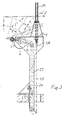
- the drum is shown with two circles 1 and 1 'in dash-dot lines, whereby the drum 1 'has the largest possible extent.
- the old one, now calm provided, web winding 9 expired web is denoted by T.
- she will by the splice element 2 from the position shown in the extended position dash-dotted position when swiveling the same taken away.
- This swiveling movement is carried out by swivel arms 3 allows, which are attached to the stand 12, which is also the first Deflection roller 5 carries for the web. Further deflecting rollers 21 and 22 guide the Train on.
- the separating device is indicated by 10, with one cutting edge 11 and an actuator 15 e.g. in the form of a hydraulic Hoist is provided.
- the separator is in the Working position drawn in which the cut of the web at stationary cutting edge or knife device through the tensioned web itself he follows.
- This is also the one working position of the splice element 2, which as tubular cylinder is indicated and a suction zone 4 in the form of a perforated jacket.
- the inside of the Pipe under negative pressure.
- the associated vacuum connection is here not shown.
- Another working position is given, in which the splice element - dotted - on the web wrap 1 smaller diameter is present.
- the top position of the Splice elements is the waiting position in which this is in remains in its original position.
- the splice element 2 When swiveling the splice element 2 into the other Working position in which the splicing process takes place, can preferably the splice element about its own axis be rotated by an appropriate drive so that the web remains taut during this process.
- the splice element is pulled out into the upper one shown end or waiting position swung back, then the new drum through a familiar one, but not here shown transport device in the place of the old Web winding 9 placed in the usual holder and then the splicing process by applying the splice element 2 to the Scope of the new drum performed.
- the last turn of the new drum an adhesive application to this splice, e.g. in form of double-sided adhesive tape.
- the path T ' runs then essentially in the horizontal direction to the first Deflection roller 5 out.
- the device is relatively simple and that also the maximum specified here Swivel range of the swivel arms 3 by a corresponding one Lifting device 14 - e.g. hydraulic type - without further ado is feasible.
- a similar arrangement results from reverse course of the reel and the old reel in In the case of an opposite winding direction of the same.
- the arrangement according to the invention shown in Figure 2 corresponds in principle to that of Figure 1. Im only the knife device has been significantly changed.
- Stand 24 is provided next to the drum, which moves away from the unwind stand 41 with the bearing 36 of the respective Drums are located.
- the knife device consists of the Knife 11, an elongated, rod or bar-shaped Beam 31 and side beams 25, which are elongated Hold carrier 31.
- the carrier 31 extends along the Drums as well as the knife 11 '.
- the side straps 25 are here in the guideways 27 by means of rollers 29 and 30 the stand 24 out.
- the drive takes place via a chain 34 and one of the sprockets 32 and 33 via one here Drive motor, not shown, e.g. an electric motor.
- Figure 3 is a similar drive device for the Knife device shown, here also a chain, a rope or a toothed belt 40 can be used.
- the drive is via a hydraulic one or pneumatic actuating cylinder 39 and a lever 38, the each on the side supports 25 of the knife device is attached.
- Figure 4 is a similar device with respect to Knife device shown as in Figure 2.
- the guideway of the slide shoe 53 is indicated with 54.
- the whole thing is from a console 56 worn with attachment 57. This rests on a stand 12 ', which is also the first pulley 5' for the web records.
- Knife actuation device has the advantage that Obstacles can be avoided by the knife, being in In these cases the obstacle is practically the old web winding 9 is.
- Through the guideways can be quite cheap Cutting position and in this way comes very close to the upper circumferential region of the web winding 9 when it is in has reached its cutting position.
Landscapes
- Replacement Of Web Rolls (AREA)
- Manufacture Of Macromolecular Shaped Articles (AREA)
- Exchange Systems With Centralized Control (AREA)
Claims (10)
- Dispositif pour raccorder la fin de bande d'une bobine qui se termine, placée sur un support, à la couche extérieure, pourvue de moyens adhésifs, d'une bobine suivante chargée en place, comprenant un élément d'assemblage qui s' étend transversalement à la bande et peut être appliqué contre la bobine suivante, présentant les caractéristiques suivantes:1.1. l'élément d'assemblage est un tube d'assemblage (2) perforé, soumis à une pression négative, qui peut être déplacé depuis une position d'attente en direction de la trajectoire de la bande (T) de la bobine (9) qui se termine,1.2. un couteau de séparation (11) peut être amené dans une position de travail, entre la bobine (9) et le tube d'assemblage (2), caractérisé par les caractéristiques suivantes:1.3. lors de l'avancée du tube d'assemblage (2) en direction de la bande (T), la bande (T) à l'arrêt de la bobine (9) qui se termine est coupée par le couteau de séparation (11) stationnaire dans la position de travail,1.4. le tube d'assemblage avec la fin de bande tenue par la pression négative est amené dans une position, à partir de laquelle il peut être appliqué contre la bobine (1) suivante après un changement de bobine,1.5. le tube de d'assemblage (2) peut être mis en rotation autour de son propre axe par un moyen d'entraínement.
- Dispositif selon la revendication 1, caractérisé par le fait que l'élément □'assemblage (2) est monté sur des bras porteurs (3), montés sur un support (12) sur lequel est prévu un premier rouleau de renvoi (5) pour la bande (T) qui se termine.
- Dispositif selon une des revendications 1 ou 2, caractérisé par le fait qu'un dispositif d'actionnement de couteau comporte un montant (24) de chaque côté d'un bâti de dévidage (41) pour la bobine (1', 1') , lesquels montants sont disposés à distance de la surface extérieure de la bobine et présentent chacun une coulisse (27) pour un porte-couteau (25, 31) aux fins d'amener le couteau de séparation (11') de la position d'attente dans la position de coupe.

- Dispositif selon la revendication 3, caractérisé par le fait que le porte-couteau comprend un support (31) allongé en forme de barreau ou de poutre pour le couteau (11'), qui s'étend le long de la bobine (1', 1'') et est tenu par des traverses latérales (25) guidées à l'aide d'éléments de guidage (29, 30) dans les coulisses (27) des montants (24).
- Dispositif selon la revendication 3 ou 4, caractérisé par le fait que la coulisse (27) dans sa section proche de la position de coupe du couteau (11') est coudée en direction dudit couteau et, pour le reste, s'étend dans une direction qui s'écarte faiblement de la verticale.
- Dispositif selon la revendication 5, caractérisé par le fait que la coulisse (27), à l'exception de sa partie (27') coudée, forme un angle de 30° maximum avec la verticale.
- Dispositif selon une des revendications 3 à 6, caractérisé par le fait que les éléments d'entraínement du porte-couteau (25, 31) sont des chaínes (34), des courroies ou des câbles.
- Dispositif selon une des revendications 3 à 7, caractérisé par le fait que l'extrémité supérieure de la coulisse (27) pour le porte-couteau (25, 31) est située au-dessus du plan horizontal (H) passant par l'axe de bobine (1', 1''), de sorte que le couteau de séparation (11'), dans la position de coupe, avance en direction de la surface extérieure supérieure de la bobine (9) de bande largement dévidée.
- Dispositif selon la revendication 7, caractérisé par le fait que l'entraínement du système de couteau a lieu par l'intermédiaire d'un moteur d'entraínement qui entraíne la chaíne (34) par l'intermédiaire d'un pignon à chaíne (22, 33).
- Dispositif selon la revendication 7 ou 8, caractérisé par le fait qu'il est prévu comme moyen d'entraínement pour le porte-couteau des vérins (39) hydrauliques ou pneumatiques associés aux câbles (40), aux courroies ou aux chaínes.
Applications Claiming Priority (2)
| Application Number | Priority Date | Filing Date | Title |
|---|---|---|---|
| DE4401963A DE4401963C2 (de) | 1994-01-25 | 1994-01-25 | Einrichtung zum Herstellen einer Bahnverbindung |
| DE4401963 | 1994-01-25 |
Publications (3)
| Publication Number | Publication Date |
|---|---|
| EP0668228A2 EP0668228A2 (fr) | 1995-08-23 |
| EP0668228A3 EP0668228A3 (fr) | 1996-09-25 |
| EP0668228B1 true EP0668228B1 (fr) | 2000-08-02 |
Family
ID=6508556
Family Applications (1)
| Application Number | Title | Priority Date | Filing Date |
|---|---|---|---|
| EP94120633A Expired - Lifetime EP0668228B1 (fr) | 1994-01-25 | 1994-12-24 | Installation pour établir un raccordement de bandes |
Country Status (8)
| Country | Link |
|---|---|
| US (1) | US5740982A (fr) |
| EP (1) | EP0668228B1 (fr) |
| JP (1) | JPH07291492A (fr) |
| KR (1) | KR950031272A (fr) |
| AT (1) | ATE195110T1 (fr) |
| CA (1) | CA2140998C (fr) |
| DE (2) | DE4401963C2 (fr) |
| FI (1) | FI950185A (fr) |
Families Citing this family (7)
| Publication number | Priority date | Publication date | Assignee | Title |
|---|---|---|---|---|
| US6161793A (en) * | 1999-01-22 | 2000-12-19 | Lindstrand; Bruce L. | Paper unwind splicer for drawing from the top or bottom of a reel |
| IT1318105B1 (it) * | 2000-07-05 | 2003-07-23 | Giovanni Gambini | Dispositivo per la giunzione di un lembo finale di una bobina di carta in esaurimento con il lembo iniziale di una nuova bobina. |
| DE10041969B4 (de) * | 2000-08-25 | 2012-03-29 | Goss Contiweb B.V. | Verfahren und Vorrichtung zum Kürzen der Fahne im Anschluss an einen Rollenwechsel |
| DE20019539U1 (de) * | 2000-11-17 | 2001-02-15 | Valmet Corp., Helsinki | Anordnung zur Herstellung einer Bahnverbindung |
| DE10058458B4 (de) * | 2000-11-24 | 2005-12-08 | Koenig & Bauer Ag | Vorrichtung zum Verbinden zweier Materialbahnen |
| US7513277B2 (en) * | 2007-05-23 | 2009-04-07 | Voith Patent Gmbh | Low tensile creep belt |
| EP2982629A1 (fr) * | 2014-08-08 | 2016-02-10 | Sidel S.p.a. Con Socio Unico | Appareil et procédé pour épisser des bandes pourvues de motifs répétés |
Family Cites Families (6)
| Publication number | Priority date | Publication date | Assignee | Title |
|---|---|---|---|---|
| DE3440107A1 (de) * | 1984-11-02 | 1986-05-22 | Jagenberg AG, 4000 Düsseldorf | Verfahren und vorrichtung zum verbinden einer ersten, zu einer verarbeitungsmaschine ablaufenden materialbahn mit dem anfang einer aufgewickelten zweiten materialbahn |
| EP0183011B1 (fr) * | 1984-11-02 | 1988-03-30 | JAGENBERG Aktiengesellschaft | Procédé et dispositif pour épisser des bandes |
| DE3723601A1 (de) * | 1987-07-17 | 1989-02-02 | Voith Gmbh J M | Maschine zum wickeln einer papier- oder kartonbahn |
| DE3723600A1 (de) * | 1987-07-17 | 1989-01-26 | Voith Gmbh J M | Abwickelvorrichtung fuer papier- oder kartonbahn |
| DE3901854A1 (de) * | 1989-01-23 | 1990-07-26 | Jagenberg Ag | Vorrichtung zum verbinden von materialbahnen |
| DE3907136A1 (de) * | 1989-03-06 | 1990-09-13 | Jagenberg Ag | Vorrichtung zum verbinden von materialbahnen |
-
1994
- 1994-01-25 DE DE4401963A patent/DE4401963C2/de not_active Expired - Fee Related
- 1994-12-24 AT AT94120633T patent/ATE195110T1/de not_active IP Right Cessation
- 1994-12-24 DE DE59409468T patent/DE59409468D1/de not_active Expired - Fee Related
- 1994-12-24 EP EP94120633A patent/EP0668228B1/fr not_active Expired - Lifetime
-
1995
- 1995-01-16 FI FI950185A patent/FI950185A/fi not_active IP Right Cessation
- 1995-01-24 CA CA002140998A patent/CA2140998C/fr not_active Expired - Fee Related
- 1995-01-24 KR KR1019950001156A patent/KR950031272A/ko not_active Application Discontinuation
- 1995-01-25 US US08/377,926 patent/US5740982A/en not_active Expired - Fee Related
- 1995-01-25 JP JP7010217A patent/JPH07291492A/ja active Pending
Also Published As
| Publication number | Publication date |
|---|---|
| FI950185A (fi) | 1995-07-26 |
| CA2140998C (fr) | 2001-07-03 |
| ATE195110T1 (de) | 2000-08-15 |
| DE59409468D1 (de) | 2000-09-07 |
| JPH07291492A (ja) | 1995-11-07 |
| EP0668228A3 (fr) | 1996-09-25 |
| KR950031272A (ko) | 1995-12-18 |
| DE4401963A1 (de) | 1994-06-09 |
| DE4401963C2 (de) | 1998-09-03 |
| US5740982A (en) | 1998-04-21 |
| CA2140998A1 (fr) | 1995-07-26 |
| EP0668228A2 (fr) | 1995-08-23 |
| FI950185A0 (fi) | 1995-01-16 |
Similar Documents
| Publication | Publication Date | Title |
|---|---|---|
| DE69208828T2 (de) | Vorrichtung zum Umwickeln von ringförmigen Gegenständen | |
| DE2721881C2 (de) | Wickelmaschine für Papierbahnen | |
| DE2038913C3 (de) | Vorrichtung zum Abschneiden streifenförmiger Abschnitte von einer Reifenverstärkungsbahn und zum Aufbringen der abgeschnittenen Abschnitte auf eine Reifenaufbautrommel | |
| EP0458112A1 (fr) | Dispositif pour raccorder des bandes | |
| DE19540689C2 (de) | Schneideeinrichtung | |
| DE3314319C2 (de) | Vorrichtung zum Spleißen von Bändern | |
| EP0668228B1 (fr) | Installation pour établir un raccordement de bandes | |
| DE60009628T2 (de) | Vorrichtung zur Handhabung von Spulen | |
| DE19923930A1 (de) | Vorrichtung zum Aufwickeln einer Materialbahn | |
| DE69900525T2 (de) | Vorrichtung und Verfahren zum Entfernen des Verpackungsmaterials von einer Materialbahnrolle | |
| CH680670A5 (fr) | ||
| DE3538889C2 (de) | Streifenschneidanlage | |
| DE2553499C3 (de) | Vorrichtung zum Verdichten und Umbinden von ringförmigen Gegenständen | |
| DE3914776A1 (de) | Verfahren und vorrichtung zum aufwickeln und querschneiden einer laufenden warenbahn | |
| DE2853548A1 (de) | Verfahren und vorrichtung zum abgestimmten anheben der fuehrungsschlitten einer aufwickelrolle beim achslosen aufwickeln von warenbahnen | |
| DE8717353U1 (de) | Vorrichtung zum schrittweisen Bewegen und Spannen des Schleifbands von Tellerfuß-Durchlauf-Schleifmaschinen | |
| DE2503545A1 (de) | Verfahren und vorrichtung zum spulenwechseln an textilmaschinen, insbesondere an offen-end-spinnmaschinen | |
| DE2516226B2 (de) | Vorrichtung zum anwinkeln eines bahnfoermigen materials, insbesondere furnierbahn | |
| EP1283184A2 (fr) | Méthode et dispositif pour la préparation d'un rouleau de bande de papier en stockage pour le changement du rouleau en marche | |
| DE4213863C2 (de) | Vorrichtung zum Verbinden einer Papierbahn mit einem Papierbahn-Einfädelteil | |
| DE3804402A1 (de) | Tragwalzenwickelmaschine zum aufwickeln einer materialbahn, insbesondere einer papier- oder kartonbahn, auf wickelhuelsen | |
| DE10140365A1 (de) | Vorrichtung zum Durchtrennen einer laufender Materialbahn und zum Festlegen des nachlaufenden Bahnanfangs auf einer Wickelhülse | |
| DE69700206T2 (de) | Umreifungsmaschine für Bandmaterialrollen | |
| EP1033304A1 (fr) | Procédé et appareillage pour ficeler des bobines de feuillard | |
| DE2249367C3 (de) | Vorrichtung zum kontinuierlichen Aufwickeln dünnen bahnförmigen Guts |
Legal Events
| Date | Code | Title | Description |
|---|---|---|---|
| PUAI | Public reference made under article 153(3) epc to a published international application that has entered the european phase |
Free format text: ORIGINAL CODE: 0009012 |
|
| AK | Designated contracting states |
Kind code of ref document: A2 Designated state(s): AT CH DE ES FR GB IT LI SE |
|
| PUAL | Search report despatched |
Free format text: ORIGINAL CODE: 0009013 |
|
| AK | Designated contracting states |
Kind code of ref document: A3 Designated state(s): AT CH DE ES FR GB IT LI SE |
|
| 17P | Request for examination filed |
Effective date: 19970204 |
|
| 17Q | First examination report despatched |
Effective date: 19980827 |
|
| RAP1 | Party data changed (applicant data changed or rights of an application transferred) |
Owner name: VOITH SULZER PAPIERTECHNIK PATENT GMBH |
|
| GRAG | Despatch of communication of intention to grant |
Free format text: ORIGINAL CODE: EPIDOS AGRA |
|
| GRAG | Despatch of communication of intention to grant |
Free format text: ORIGINAL CODE: EPIDOS AGRA |
|
| GRAH | Despatch of communication of intention to grant a patent |
Free format text: ORIGINAL CODE: EPIDOS IGRA |
|
| GRAH | Despatch of communication of intention to grant a patent |
Free format text: ORIGINAL CODE: EPIDOS IGRA |
|
| GRAA | (expected) grant |
Free format text: ORIGINAL CODE: 0009210 |
|
| AK | Designated contracting states |
Kind code of ref document: B1 Designated state(s): AT CH DE ES FR GB IT LI SE |
|
| PG25 | Lapsed in a contracting state [announced via postgrant information from national office to epo] |
Ref country code: IT Free format text: LAPSE BECAUSE OF FAILURE TO SUBMIT A TRANSLATION OF THE DESCRIPTION OR TO PAY THE FEE WITHIN THE PRE;WARNING: LAPSES OF ITALIAN PATENTS WITH EFFECTIVE DATE BEFORE 2007 MAY HAVE OCCURRED AT ANY TIME BEFORE 2007. THE CORRECT EFFECTIVE DATE MAY BE DIFFERENT FROM THE ONE RECORDED.SCRIBED TIME-LIMIT Effective date: 20000802 Ref country code: GB Free format text: LAPSE BECAUSE OF FAILURE TO SUBMIT A TRANSLATION OF THE DESCRIPTION OR TO PAY THE FEE WITHIN THE PRESCRIBED TIME-LIMIT Effective date: 20000802 Ref country code: FR Free format text: LAPSE BECAUSE OF FAILURE TO SUBMIT A TRANSLATION OF THE DESCRIPTION OR TO PAY THE FEE WITHIN THE PRESCRIBED TIME-LIMIT Effective date: 20000802 Ref country code: ES Free format text: THE PATENT HAS BEEN ANNULLED BY A DECISION OF A NATIONAL AUTHORITY Effective date: 20000802 |
|
| REF | Corresponds to: |
Ref document number: 195110 Country of ref document: AT Date of ref document: 20000815 Kind code of ref document: T |
|
| REG | Reference to a national code |
Ref country code: CH Ref legal event code: EP |
|
| REF | Corresponds to: |
Ref document number: 59409468 Country of ref document: DE Date of ref document: 20000907 |
|
| PG25 | Lapsed in a contracting state [announced via postgrant information from national office to epo] |
Ref country code: SE Free format text: LAPSE BECAUSE OF FAILURE TO SUBMIT A TRANSLATION OF THE DESCRIPTION OR TO PAY THE FEE WITHIN THE PRESCRIBED TIME-LIMIT Effective date: 20001102 |
|
| EN | Fr: translation not filed | ||
| GBV | Gb: ep patent (uk) treated as always having been void in accordance with gb section 77(7)/1977 [no translation filed] |
Effective date: 20000802 |
|
| PGFP | Annual fee paid to national office [announced via postgrant information from national office to epo] |
Ref country code: AT Payment date: 20010313 Year of fee payment: 7 |
|
| PGFP | Annual fee paid to national office [announced via postgrant information from national office to epo] |
Ref country code: CH Payment date: 20010315 Year of fee payment: 7 |
|
| PLBE | No opposition filed within time limit |
Free format text: ORIGINAL CODE: 0009261 |
|
| STAA | Information on the status of an ep patent application or granted ep patent |
Free format text: STATUS: NO OPPOSITION FILED WITHIN TIME LIMIT |
|
| 26N | No opposition filed | ||
| PG25 | Lapsed in a contracting state [announced via postgrant information from national office to epo] |
Ref country code: AT Free format text: LAPSE BECAUSE OF NON-PAYMENT OF DUE FEES Effective date: 20011224 |
|
| PG25 | Lapsed in a contracting state [announced via postgrant information from national office to epo] |
Ref country code: LI Free format text: LAPSE BECAUSE OF NON-PAYMENT OF DUE FEES Effective date: 20011231 Ref country code: CH Free format text: LAPSE BECAUSE OF NON-PAYMENT OF DUE FEES Effective date: 20011231 |
|
| REG | Reference to a national code |
Ref country code: CH Ref legal event code: PL |
|
| PGFP | Annual fee paid to national office [announced via postgrant information from national office to epo] |
Ref country code: DE Payment date: 20040112 Year of fee payment: 10 |
|
| PG25 | Lapsed in a contracting state [announced via postgrant information from national office to epo] |
Ref country code: DE Free format text: LAPSE BECAUSE OF NON-PAYMENT OF DUE FEES Effective date: 20050701 |