EP0668228B1 - Installation for producing a web splice - Google Patents
Installation for producing a web splice Download PDFInfo
- Publication number
- EP0668228B1 EP0668228B1 EP94120633A EP94120633A EP0668228B1 EP 0668228 B1 EP0668228 B1 EP 0668228B1 EP 94120633 A EP94120633 A EP 94120633A EP 94120633 A EP94120633 A EP 94120633A EP 0668228 B1 EP0668228 B1 EP 0668228B1
- Authority
- EP
- European Patent Office
- Prior art keywords
- knife
- winding roll
- web
- splice
- strip
- Prior art date
- Legal status (The legal status is an assumption and is not a legal conclusion. Google has not performed a legal analysis and makes no representation as to the accuracy of the status listed.)
- Expired - Lifetime
Links
Images


Classifications
-
- B—PERFORMING OPERATIONS; TRANSPORTING
- B65—CONVEYING; PACKING; STORING; HANDLING THIN OR FILAMENTARY MATERIAL
- B65H—HANDLING THIN OR FILAMENTARY MATERIAL, e.g. SHEETS, WEBS, CABLES
- B65H19/00—Changing the web roll
- B65H19/10—Changing the web roll in unwinding mechanisms or in connection with unwinding operations
- B65H19/18—Attaching, e.g. pasting, the replacement web to the expiring web
- B65H19/1842—Attaching, e.g. pasting, the replacement web to the expiring web standing splicing, i.e. the expiring web being stationary during splicing contact
- B65H19/1847—Attaching, e.g. pasting, the replacement web to the expiring web standing splicing, i.e. the expiring web being stationary during splicing contact taking place on the replacement roll
-
- B—PERFORMING OPERATIONS; TRANSPORTING
- B65—CONVEYING; PACKING; STORING; HANDLING THIN OR FILAMENTARY MATERIAL
- B65H—HANDLING THIN OR FILAMENTARY MATERIAL, e.g. SHEETS, WEBS, CABLES
- B65H19/00—Changing the web roll
- B65H19/10—Changing the web roll in unwinding mechanisms or in connection with unwinding operations
- B65H19/20—Cutting-off the expiring web
-
- B—PERFORMING OPERATIONS; TRANSPORTING
- B65—CONVEYING; PACKING; STORING; HANDLING THIN OR FILAMENTARY MATERIAL
- B65H—HANDLING THIN OR FILAMENTARY MATERIAL, e.g. SHEETS, WEBS, CABLES
- B65H2406/00—Means using fluid
- B65H2406/30—Suction means
Definitions
- the invention relates to a device according to the preamble of Claim 1
- a device is known from EP 462 157 B1.
- This device there is a cutting knife on the Splicing device, which is designed as a slim hollow cylinder and a Has suction zone.
- the cutting knife is arranged in a groove that in the splice element is formed.
- the cutting knife has its own Actuator that is set in motion during the cutting process. It this naturally results in a relatively complicated structure of the Splice elements with a relatively strong weakening of the same in in terms of stress, because the groove the cylindrical shell interrupts.
- DE 34 40 107 C2 describes a device for connecting the end of one running material web with the beginning of a second material web.
- a knife arranged separately from the splice element is provided, which is moved against a stretched track section.
- DE 39 01 854 A1 describes a similar device in which the web against the Cutting edge of a cutting device is moved; the cutting device and the splice element are arranged separately from one another.
- EP-A-0 299 180 discloses an apparatus for connecting the web end an outgoing winding roll with the outer layer of a subsequent one Idle reel with a perforated splicer tube. According to this The splicer tube can be rotated around its own axis. Of however, there is no question of an independent drive. That splicer tube is thus not arbitrarily angularly positionable.
- the invention has for its object a device according to the Preamble of claim 1 to be designed such that the web during the Splicing is held tight, so that the splicing to a successful result.
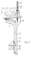
- the drum is shown with two circles 1 and 1 'in dash-dot lines, whereby the drum 1 'has the largest possible extent.
- the old one, now calm provided, web winding 9 expired web is denoted by T.
- she will by the splice element 2 from the position shown in the extended position dash-dotted position when swiveling the same taken away.
- This swiveling movement is carried out by swivel arms 3 allows, which are attached to the stand 12, which is also the first Deflection roller 5 carries for the web. Further deflecting rollers 21 and 22 guide the Train on.
- the separating device is indicated by 10, with one cutting edge 11 and an actuator 15 e.g. in the form of a hydraulic Hoist is provided.
- the separator is in the Working position drawn in which the cut of the web at stationary cutting edge or knife device through the tensioned web itself he follows.
- This is also the one working position of the splice element 2, which as tubular cylinder is indicated and a suction zone 4 in the form of a perforated jacket.
- the inside of the Pipe under negative pressure.
- the associated vacuum connection is here not shown.
- Another working position is given, in which the splice element - dotted - on the web wrap 1 smaller diameter is present.
- the top position of the Splice elements is the waiting position in which this is in remains in its original position.
- the splice element 2 When swiveling the splice element 2 into the other Working position in which the splicing process takes place, can preferably the splice element about its own axis be rotated by an appropriate drive so that the web remains taut during this process.
- the splice element is pulled out into the upper one shown end or waiting position swung back, then the new drum through a familiar one, but not here shown transport device in the place of the old Web winding 9 placed in the usual holder and then the splicing process by applying the splice element 2 to the Scope of the new drum performed.
- the last turn of the new drum an adhesive application to this splice, e.g. in form of double-sided adhesive tape.
- the path T ' runs then essentially in the horizontal direction to the first Deflection roller 5 out.
- the device is relatively simple and that also the maximum specified here Swivel range of the swivel arms 3 by a corresponding one Lifting device 14 - e.g. hydraulic type - without further ado is feasible.
- a similar arrangement results from reverse course of the reel and the old reel in In the case of an opposite winding direction of the same.
- the arrangement according to the invention shown in Figure 2 corresponds in principle to that of Figure 1. Im only the knife device has been significantly changed.
- Stand 24 is provided next to the drum, which moves away from the unwind stand 41 with the bearing 36 of the respective Drums are located.
- the knife device consists of the Knife 11, an elongated, rod or bar-shaped Beam 31 and side beams 25, which are elongated Hold carrier 31.
- the carrier 31 extends along the Drums as well as the knife 11 '.
- the side straps 25 are here in the guideways 27 by means of rollers 29 and 30 the stand 24 out.
- the drive takes place via a chain 34 and one of the sprockets 32 and 33 via one here Drive motor, not shown, e.g. an electric motor.
- Figure 3 is a similar drive device for the Knife device shown, here also a chain, a rope or a toothed belt 40 can be used.
- the drive is via a hydraulic one or pneumatic actuating cylinder 39 and a lever 38, the each on the side supports 25 of the knife device is attached.
- Figure 4 is a similar device with respect to Knife device shown as in Figure 2.
- the guideway of the slide shoe 53 is indicated with 54.
- the whole thing is from a console 56 worn with attachment 57. This rests on a stand 12 ', which is also the first pulley 5' for the web records.
- Knife actuation device has the advantage that Obstacles can be avoided by the knife, being in In these cases the obstacle is practically the old web winding 9 is.
- Through the guideways can be quite cheap Cutting position and in this way comes very close to the upper circumferential region of the web winding 9 when it is in has reached its cutting position.
Abstract
Description
Die Erfindung betrifft eine Einrichtung entsprechend dem Oberbegriff des Patentanspruchs 1. Eine solche Einrichtung ist bekannt aus der EP 462 157 B1. Bei dieser Einrichtung befindet sich ein Trennmesser auf der Splicevorrichtung, die als ein schlanker Hohlzylinder ausgebildet ist und eine Saugzone aufweist. Dabei ist das Trennmesser in einer Nut angeordnet, die in dem Spliceelement ausgebildet ist. Das Trennmesser hat eine eigene Betätigungsvorrichtung, die beim Trennvorgang in Bewegung gesetzt wird. Es ergibt sich dadurch natürlich ein relativ komplizierter Aufbau des Spliceelements mit einer relativ starken Schwächung desselben in beanspruchungsmäßiger Hinsicht, weil die Nut den zylindrischen Mantel unterbricht.The invention relates to a device according to the preamble of Claim 1 Such a device is known from EP 462 157 B1. With this device there is a cutting knife on the Splicing device, which is designed as a slim hollow cylinder and a Has suction zone. The cutting knife is arranged in a groove that in the splice element is formed. The cutting knife has its own Actuator that is set in motion during the cutting process. It this naturally results in a relatively complicated structure of the Splice elements with a relatively strong weakening of the same in in terms of stress, because the groove the cylindrical shell interrupts.
DE 34 40 107 C2 beschreibt eine Einrichtung zum Verbinden des Endes einer ablaufenden Materialbahn mit dem Anfang einer zweiten Materialbahn. Dabei ist ein vom Spliceelement getrennt angeordnetes Messer vorgesehen, das gegen einen gespannten Bahnabschnitt bewegt wird. DE 39 01 854 A1 beschreibt eine ähnliche Vorrichtung, bei welcher die Bahn gegen die Schneide einer Schneidvorrichtung bewegt wird; die Schneidvorrichtung und das Spliceelement sind dabei voneinander getrennt angeordnet.DE 34 40 107 C2 describes a device for connecting the end of one running material web with the beginning of a second material web. Here a knife arranged separately from the splice element is provided, which is moved against a stretched track section. DE 39 01 854 A1 describes a similar device in which the web against the Cutting edge of a cutting device is moved; the cutting device and the splice element are arranged separately from one another.
EP-A-0 299 180 offenbart eine Vorrichtung zum Verbinden des Bahnendes einer auslaufenden Wickelrolle mit der äußeren Lage einer nachfolgenden Wickelrolle im Ruhezustand, mit einem perforierten Splicerohr. Gemäß diesem Dokument ist zwar das Splicerohr um die eigene Achse verdrehbar. Von einem eigenen Antrieb ist jedoch nicht die Rede. Jenes Splicerohr ist somit nicht willkürlich winkelpositionierbar. EP-A-0 299 180 discloses an apparatus for connecting the web end an outgoing winding roll with the outer layer of a subsequent one Idle reel with a perforated splicer tube. According to this The splicer tube can be rotated around its own axis. Of however, there is no question of an independent drive. That splicer tube is thus not arbitrarily angularly positionable.
Der Erfindung liegt die Aufgabe zugrunde, eine Vorrichtung gemäß dem Oberbegriff von Anspruch 1 derart zu gestalten, daß die Bahn während des Splicevorganges strammgehalten wird, so daß der Splicevorgang zu einem erfolgreichen Ergebnis führt.The invention has for its object a device according to the Preamble of claim 1 to be designed such that the web during the Splicing is held tight, so that the splicing to a successful result.
Diese Aufgabe wird durch die Merkmale von Anspruch 1 gelöst.This object is solved by the features of claim 1.
Nachfolgend wird die Erfindung anhand der Figuren der Zeichnung erläutert, welche jeweils eine Seitenansicht, zum Teil ausschnittweise, der verschiedenen Erfindungsvarianten in prinzipieller Darstellung wiedergeben.The invention is explained below with reference to the figures of the drawing, each of which is a side view, partly in section, of reproduce different variants of the invention in principle.
Der Tambour ist mit zwei Kreisen 1 und 1' strichpunktiert dargestellt, wobei
der Tambour 1' den größtmöglichen Umfang hat. Die vom alten, jetzt ruhig
gestellten, Bahnwickel 9 abgelaufene Bahn ist mit T bezeichnet. Sie wird
durch das Spliceelement 2 aus der ausgezogen dargestellten Stellung in die
strichpunktierte Stellung bei der Schwenkbewegung desselben
mitgenommen. Diese Schwenkbewegung wird durch Schwenkarme 3
ermöglicht, die an dem Ständer 12 befestigt sind, der auch die erste
Umlenkwalze 5 für die Bahn trägt. Weitere Umlenkwalzen 21 und 22 leiten die
Bahn weiter. Die Trennvorrichtung ist mit 10 angegeben, wobei eine Schneide
11 und ein Betätigungsantrieb 15 z.B. in Form eines hydraulischen
Hubwerkes vorgesehen ist. In der Figur ist die Trennvorrichtung in der
Arbeitsposition gezeichnet, in welcher die Durchtrennung der Bahn bei
ruhender Schneide bzw. Messervorrichtung durch die gespannte Bahn selbst
erfolgt. Dies ist auch die eine Arbeitsposition des Spliceelements 2, das als
rohrförmiger Zylinder angedeutet ist und eine Saugzone 4 in Form eines
durchlöcherten Mantels aufweist. Beim Saugvorgang wird das Innere des
Rohres unter Unterdruck gesetzt. Der zugehörige Unterdruckanschluß ist hier
nicht dargestellt. Es ist eine weitere Arbeitsposition angegeben, bei welcher
das Spliceelement - gestrichelt ausgeführt - an dem Bahnwickel
1 kleineren Durchmessers anliegt. Die oberste Position des
Spliceelements ist die Warteposition, in welcher dieses in
seiner Ausgangsstellung verharrt. Durch Herabschwenken des
Spliceelements aus dieser Position in die untere
Arbeitsposition entlang dem Bogen S wird die Bahn
eingefangen, indem sie sich an die Saugzone des
Spliceelements anlegt. Dann kann der Trennvorgang durch das
Messer 11 erfolgen, wobei dieses jedoch schon vorher in
diese Arbeitsposition gebracht werden muß, in welcher es
dann einige Zeit bis zum Trennvorgang verharrt.The drum is shown with two circles 1 and 1 'in dash-dot lines, whereby
the drum 1 'has the largest possible extent. The old one, now calm
provided, web winding 9 expired web is denoted by T. she will
by the
Beim Hochschwenken des Spliceelements 2 in die weitere
Arbeitsposition, in welcher der Splicevorgang stattfindet,
kann vorzugsweise das Spliceelement um seine eigene Achse
durch einen entsprechenden Antrieb verdreht werden, so daß
die Bahn während dieses Vorganges strammgehalten bleibt.
Das Spliceelement wird in die obere, ausgezogen
dargestellte End- oder Warteposition zurückgeschwenkt, dann
der neue Tambour durch eine bekannte, hier aber nicht
dargestellte Transportvorrichtung an die Stelle des alten
Bahnwickels 9 in die übliche Halterung eingelegt und dann
der Splicevorgang durch Anlegen des Spliceelements 2 an den
Umfang des neuen Tambours durchgeführt. Für diesen Zweck
weist die letzte Windung des neuen Tambours natürlich an
dieser Splicestelle einen Klebeauftrag, z.B. in Form eines
doppelseitigen Klebestreifens, auf. Die Bahn T' verläuft
dann im wesentlichen in horizontaler Richtung zur ersten
Umlenkrolle 5 hin.When swiveling the
Man erkennt, daß die Einrichtung relativ einfach aufgebaut ist, und daß auch der hier angegebene maximale Schwenkbereich der Schwenkarme 3 durch eine entsprechende Hubvorrichtung 14 - z.B. hydraulischer Art - ohne weiteres durchführbar ist. Eine ähnliche Anordnung ergibt sich bei umgekehrten Bahnablauf von Tambour und altem Bahnwickel im Fall einer entgegengesetzten Wickelrichtung derselben. It can be seen that the device is relatively simple and that also the maximum specified here Swivel range of the swivel arms 3 by a corresponding one Lifting device 14 - e.g. hydraulic type - without further ado is feasible. A similar arrangement results from reverse course of the reel and the old reel in In the case of an opposite winding direction of the same.
Die in Figur 2 dargestellte erfindungsgemäße Anordnung
entspricht im Prinzip derjenigen von Figur 1. Im
wesentlichen geändert worden ist nur die Messervorrichtung.
Zur Lagerung der Messervorrichtung sind hier jeweils ein
Ständer 24 neben dem Tambour vorgesehen, die sich entfernt
von dem Abrollgestell 41 mit der Lagerung 36 des jeweiligen
Tambours befinden. Die Messervorrichtung besteht aus dem
Messer 11, einem langgestreckten, stab- oder balkenförmigen
Träger 31 und Seitenträgern 25, die den langgestreckten
Träger 31 halten. Der Träger 31 erstreckt sich längs des
Tambours ebenso wie das Messer 11'. Die Seitenträger 25
sind hier mittels Rollen 29 und 30 in den Führungsbahnen 27
der Ständer 24 geführt. Der Antrieb erfolgt über eine Kette
34 und eines der Kettenräder 32 und 33 über einen hier
nicht dargestellten Antriebsmotor, z.B. einen Elektromotor.
Das obere Ende der Führungsbahn 27 und dementsprechend die
Schneidposition des Messers 11' befindet sich oberhalb der
durch die Tambourachse verlaufenden Horizontalebene H. Auch
hier wird der Schneidvorgang durch das Herabschwenken der
Splicevorrichtung 2 in die hier angegebene untere Position
im wesentlichen allein durch die Bahnspannung bewirkt.
Weitere Einzelheiten der Hilfseinrichtungen zur Bewegung
des Tambours sind hier ebenfalls in Figur 1 nicht
dargestellt. Zu erwähnen ist noch, daß das Abrollgestell 41
auf einer Grundplatte 42 des Fundaments ruht.The arrangement according to the invention shown in Figure 2
corresponds in principle to that of Figure 1. Im
only the knife device has been significantly changed.
There are one for storing the knife device
Stand 24 is provided next to the drum, which moves away
from the unwind stand 41 with the bearing 36 of the respective
Drums are located. The knife device consists of the
Knife 11, an elongated, rod or bar-
In Figur 3 ist eine ähnliche Antriebseinrichtung für die
Messervorrichtung dargestellt, wobei auch hier eine Kette,
ein Seil oder auch ein Zahnriemen 40 benutzt werden kann.
Der Antrieb erfolgt hier jedoch über einen hydraulischen
oder pneumatischen Stellzylinder 39 und einen Hebel 38, der
jeweils an den Seitenträgern 25 der Messervorrichtung
befestigt ist.In Figure 3 is a similar drive device for the
Knife device shown, here also a chain,
a rope or a
In den Figuren 2 und 3 ist mit Winkel a der günstige Bereich zum Anbringen des Klebestreifens für den Splicevorgang angedeutet. Im wesentlichen verlaufen die Führungsbahnen 27, 27' und auch die Ständer 24 vertikal, vorzugsweise höchstens 30° von der Vertikalen abweichend. Dadurch wird eine sehr raumsparende Anordnung erzielt, was bei beengten Raumverhältnissen z.B. durch die Art der Ausbildung der Abrollständer günstig ist. Daher befinden sich auch in günstiger Weise die Ständer 24 - in Richtung quer zum Tambour 1, 1' - entfernt von den Rollenständern 41.In Figures 2 and 3 with angle a is the favorable Area for attaching the adhesive strip for the Splicing indicated. Essentially, the Guideways 27, 27 'and also the stands 24 vertically, preferably deviating at most 30 ° from the vertical. This results in a very space-saving arrangement, what in confined spaces e.g. by the type of Training of the unwind stand is cheap. Therefore stand 24 - in a favorable manner across the drum 1, 1 '- away from the reel stands 41.
In Figur 4 ist eine ähnliche Einrichtung bezüglich der
Messervorrichtung dargestellt wie in Figur 2. Hier ist
jedoch ein anderer Antriebs des Spliceelements 2
vorgesehen. Und zwar wird hier über einen Halter 54 eine
von einem Gleitschlitten 53 geführte Antriebsstange 50 von
der Kolbenstange 52 eines hydraulischen oder pneumatischen
Hubelements 51 betätigt. Die Führungsbahn des Gleitschuhs
53 ist mit 54 angedeutet. Das ganze wird von einer Konsole
56 mit Aufsatz 57 getragen. Diese ruht auf einem Ständer
12', der auch die erste Umlenkrolle 5' für die Bahn
aufnimmt.In Figure 4 is a similar device with respect to
Knife device shown as in Figure 2. Here is
however, another drive of the
In Figur 5 ist der Antrieb der Messervorrichtung gemäß
Figur 2 wieder auf eine etwas andere Weise variiert. Die
Seitenträger 25' für den balkenförmigen Messerträger 31 -
hier als Rohr ausgebildet - gleiten auf Rollen 29' und 30'
und werden über eine Verbindungslasche 67 von einem
Führungswagen 60 angetrieben, der mittels Rollen 61 und 62
in den Führungsbahnen 27' des Ständers 59 an einer Kette
34' bewegt wird. Diese wird wiederum über ein hier nicht
mehr erkennbares Kettenrad, das dem Kettenrad 33
entspricht, von einem Motor, z.B. einem Elektromotor,
angetrieben. Der Ständer 59 erhält noch besondere
Stabilität durch eine Versteifungsrippe 65. Die
Seitenträger 25' weisen jeweils einen Fortsatz 66 auf, an
welchem der Messerbalken 31 befestigt ist. Der Ständer 59
kann zu seinen beiden Seiten die Führungsbahnen 27' im
wesentlichen bis zu der hier dargestellten oberen Position
des Führungswagens 60 aufweisen, so daß jeweils zwei
Rollenpaare 64 und 62 in diese Führungsbahnen eingreifen,
so daß der Führungswagen 60 recht gut geführt ist.In Figure 5, the drive of the knife device according to
Figure 2 again varies in a slightly different way. The
Side carrier 25 'for the bar-shaped knife carrier 31 -
here designed as a tube - slide on rollers 29 'and 30'
and are connected by a connecting
Die in den Figuren 2-5 dargestellte Messerbetätigungseinrichtung hat den Vorteil, daß Hindernisse von dem Messer umgangen werden können, wobei in diesen Fällen das Hindernis praktisch der alte Bahnwickel 9 ist. Durch die Führungsbahnen kann eine recht günstige Schneidposition und kommt auf diese Weise sehr nahe an den oberen Umfangsbereich des Bahnwickels 9 heran, wenn es in seine Schneidposition gelangt ist.The one shown in Figures 2-5 Knife actuation device has the advantage that Obstacles can be avoided by the knife, being in In these cases the obstacle is practically the old web winding 9 is. Through the guideways can be quite cheap Cutting position and in this way comes very close to the upper circumferential region of the web winding 9 when it is in has reached its cutting position.
Claims (10)
- Device for joining the end of a web of a running out winding roll, which is mounted in a holder, to the outer layer, which is provided with adhesive means, of a following replaced winding roll, comprising a splice element which extends transversely to the web and which is pushed against the following winding roll, with the following features:1.1: the splice element is a perforated splice tube (2) which is loaded with negative pressure and which is movable from a waiting position against the path of the web (T) of the running out winding roll (9);1.2: a separating knife (11) is movable into a working position between winding roll (9) and splice tube (2);
characterised by the following features:1.3: when dipping the splice tube (2) into the web (T), the stationary web (T) of the running out winding roll (9) is separable by the separating knife (11) which is stationary in the working position;1.4: the splice tube (2) is movable with the web end, which is held by negative pressure, into a position from where it is pressed against the following winding roll (1) following a replacement of the winding roll.1.5 the splice tube (2) is rotary around its own axis by means of a drive. - Device according to Claim 1, characterised in that the splice element (2) is mounted on support arms (3) which are mounted on a stand (12) on which is provided a first diverting roller (5) for the running out web (T).
- Device according to one of Claims 1 or 2, characterised in that a knife operating device comprises each one stand (24) on both sides of a rolling-off frame (41) for the winding roll (1, 1'') which are arranged at a distance from the winding roll periphery, which each comprise a guide path (27) for a knife holder (25, 31) so as to bring the separating knife (11') from a waiting position into a cuffing position.
- Device according to Claim 3, characterised in that the knife holder comprises a long bar- or beamshaped support (31) for the knife (11') which extends along the winding roll (1'; 1'') and which is held by lateral supports (25) which are guided by means of guide elements (29, 30) in guide tracks (27) of the stands (24).
- Device according to Claim 3 or 4, characterised in that the guide track (27) extends in its area (27') near the cuffing position of the knife (11') at an angle thereto, otherwise only slightly deviating from the vertical.
- Device according to Claim 5, characterised in that the guide track (27) deviates, with the exception of its angled area (27'), by no more than 30° from the vertical.
- Device according to one of Claims 3 to 6, characterised in that the drive elements of the knife holder (25, 31) are chains (34), belts or ropes.
- Device according to one of Claims 3 to 7, characterised in that the upper end of the guide track (27) for the knife support (25, 31) is arranged above the horizontal plane (H) which extends through the winding roll axis (1', 1''), so that the separating knife (11') extends in the cutting position towards the upper peripheral area of the substantially angled web roll (9).
- Device according to Claim 7, characterised in that the drive of the knife device is by means of a drive motor which propels the chain (34) via a toothed wheel (32, 33).
- Device according to Claim 7 or 8, characterised in that hydraulic or pneumatic setting cylinders (39) which are associated with the ropes (40), belts or chains are provided as drives for the knife holder.
Applications Claiming Priority (2)
| Application Number | Priority Date | Filing Date | Title |
|---|---|---|---|
| DE4401963A DE4401963C2 (en) | 1994-01-25 | 1994-01-25 | Device for establishing a rail connection |
| DE4401963 | 1994-01-25 |
Publications (3)
| Publication Number | Publication Date |
|---|---|
| EP0668228A2 EP0668228A2 (en) | 1995-08-23 |
| EP0668228A3 EP0668228A3 (en) | 1996-09-25 |
| EP0668228B1 true EP0668228B1 (en) | 2000-08-02 |
Family
ID=6508556
Family Applications (1)
| Application Number | Title | Priority Date | Filing Date |
|---|---|---|---|
| EP94120633A Expired - Lifetime EP0668228B1 (en) | 1994-01-25 | 1994-12-24 | Installation for producing a web splice |
Country Status (8)
| Country | Link |
|---|---|
| US (1) | US5740982A (en) |
| EP (1) | EP0668228B1 (en) |
| JP (1) | JPH07291492A (en) |
| KR (1) | KR950031272A (en) |
| AT (1) | ATE195110T1 (en) |
| CA (1) | CA2140998C (en) |
| DE (2) | DE4401963C2 (en) |
| FI (1) | FI950185A (en) |
Families Citing this family (7)
| Publication number | Priority date | Publication date | Assignee | Title |
|---|---|---|---|---|
| US6161793A (en) * | 1999-01-22 | 2000-12-19 | Lindstrand; Bruce L. | Paper unwind splicer for drawing from the top or bottom of a reel |
| IT1318105B1 (en) * | 2000-07-05 | 2003-07-23 | Giovanni Gambini | DEVICE FOR JOINING A FINAL EDGE OF A PAPER REEL WITH THE INITIAL EDGE OF A NEW REEL. |
| DE10041969B4 (en) * | 2000-08-25 | 2012-03-29 | Goss Contiweb B.V. | Method and device for shortening the flag following a roll change |
| DE20019539U1 (en) * | 2000-11-17 | 2001-02-15 | Valmet Corp | Arrangement for establishing a rail connection |
| DE10058458B4 (en) * | 2000-11-24 | 2005-12-08 | Koenig & Bauer Ag | Device for connecting two webs of material |
| US7513277B2 (en) * | 2007-05-23 | 2009-04-07 | Voith Patent Gmbh | Low tensile creep belt |
| EP2982629A1 (en) * | 2014-08-08 | 2016-02-10 | Sidel S.p.a. Con Socio Unico | An apparatus and a method for splicing webs provided with repeated patterns |
Family Cites Families (6)
| Publication number | Priority date | Publication date | Assignee | Title |
|---|---|---|---|---|
| DE3440107A1 (en) * | 1984-11-02 | 1986-05-22 | Jagenberg AG, 4000 Düsseldorf | Method and device for connecting a first web of material running to a processing machine to the start of a wound-up second web of material |
| EP0183011B1 (en) * | 1984-11-02 | 1988-03-30 | JAGENBERG Aktiengesellschaft | Method and apparatus for splicing webs |
| DE3723600A1 (en) * | 1987-07-17 | 1989-01-26 | Voith Gmbh J M | UNWINDING DEVICE FOR PAPER OR CARDBOARD |
| DE3723601A1 (en) * | 1987-07-17 | 1989-02-02 | Voith Gmbh J M | MACHINE FOR WRAPPING A PAPER OR CARDBOARD |
| DE3901854A1 (en) * | 1989-01-23 | 1990-07-26 | Jagenberg Ag | DEVICE FOR JOINING MATERIAL RAILS |
| DE3907136A1 (en) * | 1989-03-06 | 1990-09-13 | Jagenberg Ag | DEVICE FOR JOINING MATERIAL RAILS |
-
1994
- 1994-01-25 DE DE4401963A patent/DE4401963C2/en not_active Expired - Fee Related
- 1994-12-24 AT AT94120633T patent/ATE195110T1/en not_active IP Right Cessation
- 1994-12-24 EP EP94120633A patent/EP0668228B1/en not_active Expired - Lifetime
- 1994-12-24 DE DE59409468T patent/DE59409468D1/en not_active Expired - Fee Related
-
1995
- 1995-01-16 FI FI950185A patent/FI950185A/en not_active IP Right Cessation
- 1995-01-24 KR KR1019950001156A patent/KR950031272A/en not_active Application Discontinuation
- 1995-01-24 CA CA002140998A patent/CA2140998C/en not_active Expired - Fee Related
- 1995-01-25 JP JP7010217A patent/JPH07291492A/en active Pending
- 1995-01-25 US US08/377,926 patent/US5740982A/en not_active Expired - Fee Related
Also Published As
| Publication number | Publication date |
|---|---|
| DE4401963A1 (en) | 1994-06-09 |
| FI950185A0 (en) | 1995-01-16 |
| EP0668228A2 (en) | 1995-08-23 |
| JPH07291492A (en) | 1995-11-07 |
| EP0668228A3 (en) | 1996-09-25 |
| CA2140998C (en) | 2001-07-03 |
| CA2140998A1 (en) | 1995-07-26 |
| US5740982A (en) | 1998-04-21 |
| KR950031272A (en) | 1995-12-18 |
| DE4401963C2 (en) | 1998-09-03 |
| ATE195110T1 (en) | 2000-08-15 |
| DE59409468D1 (en) | 2000-09-07 |
| FI950185A (en) | 1995-07-26 |
Similar Documents
| Publication | Publication Date | Title |
|---|---|---|
| DE2721881C2 (en) | Winding machine for paper webs | |
| DE2038913C3 (en) | Apparatus for cutting strip-shaped sections from a tire reinforcing sheet and for applying the cut sections to a tire building drum | |
| EP0458112A1 (en) | Device for splicing webs | |
| DE19540689C2 (en) | Cutting device | |
| DE3314319C2 (en) | Device for splicing tapes | |
| EP0668228B1 (en) | Installation for producing a web splice | |
| DE60009628T2 (en) | Device for handling coils | |
| DE19923930A1 (en) | Device for winding a web of material | |
| CH680670A5 (en) | ||
| DE3538889C2 (en) | Strip cutting machine | |
| DE2553499C3 (en) | Device for compacting and binding ring-shaped objects | |
| DE3914776A1 (en) | METHOD AND DEVICE FOR WINDING AND CROSS-CUTTING A RUNNING GOODS | |
| DE2853548A1 (en) | METHOD AND DEVICE FOR THE TUNED LIFTING OF THE GUIDE SLIDES OF A ROLLING REEL FOR THE AXLE ROLLING OF PRODUCTS | |
| DE3440107C2 (en) | ||
| DE2503545A1 (en) | Open-end spinning bobbin change mechanism - has interconnected bobbin release and sleeve carrier to transfer and cut yarn without rotary direction channels | |
| EP0382898A2 (en) | Winding machine with bearing rollers for winding web materials | |
| DE2516226B2 (en) | DEVICE FOR ANGLE ANGLE OF A RAIL-SHAPED MATERIAL, IN PARTICULAR VENEER | |
| EP1283184A2 (en) | Method and device for the preparation of a stockage paper web for the flying roll exchange | |
| DE4213863C2 (en) | Device for connecting a paper web to a paper web threading part | |
| DE3804402A1 (en) | CARRIER ROLLING MACHINE FOR WINDING A MATERIAL SHEET, ESPECIALLY A PAPER OR CARDBOARD SHEET, ON WINDING SLEEVES | |
| DE10140365A1 (en) | Device for severing a running material web and for determining the trailing start of the web on a winding tube | |
| EP1033304A1 (en) | Process and apparatus for binding strip coils | |
| DE2249367C3 (en) | Device for continuously winding up thin, web-shaped goods | |
| EP0853579B1 (en) | Automatic wrapping machine with automatic change of wrapping material | |
| DE3135575C2 (en) | Device for the production of flaky belt rolls |
Legal Events
| Date | Code | Title | Description |
|---|---|---|---|
| PUAI | Public reference made under article 153(3) epc to a published international application that has entered the european phase |
Free format text: ORIGINAL CODE: 0009012 |
|
| AK | Designated contracting states |
Kind code of ref document: A2 Designated state(s): AT CH DE ES FR GB IT LI SE |
|
| PUAL | Search report despatched |
Free format text: ORIGINAL CODE: 0009013 |
|
| AK | Designated contracting states |
Kind code of ref document: A3 Designated state(s): AT CH DE ES FR GB IT LI SE |
|
| 17P | Request for examination filed |
Effective date: 19970204 |
|
| 17Q | First examination report despatched |
Effective date: 19980827 |
|
| RAP1 | Party data changed (applicant data changed or rights of an application transferred) |
Owner name: VOITH SULZER PAPIERTECHNIK PATENT GMBH |
|
| GRAG | Despatch of communication of intention to grant |
Free format text: ORIGINAL CODE: EPIDOS AGRA |
|
| GRAG | Despatch of communication of intention to grant |
Free format text: ORIGINAL CODE: EPIDOS AGRA |
|
| GRAH | Despatch of communication of intention to grant a patent |
Free format text: ORIGINAL CODE: EPIDOS IGRA |
|
| GRAH | Despatch of communication of intention to grant a patent |
Free format text: ORIGINAL CODE: EPIDOS IGRA |
|
| GRAA | (expected) grant |
Free format text: ORIGINAL CODE: 0009210 |
|
| AK | Designated contracting states |
Kind code of ref document: B1 Designated state(s): AT CH DE ES FR GB IT LI SE |
|
| PG25 | Lapsed in a contracting state [announced via postgrant information from national office to epo] |
Ref country code: IT Free format text: LAPSE BECAUSE OF FAILURE TO SUBMIT A TRANSLATION OF THE DESCRIPTION OR TO PAY THE FEE WITHIN THE PRE;WARNING: LAPSES OF ITALIAN PATENTS WITH EFFECTIVE DATE BEFORE 2007 MAY HAVE OCCURRED AT ANY TIME BEFORE 2007. THE CORRECT EFFECTIVE DATE MAY BE DIFFERENT FROM THE ONE RECORDED.SCRIBED TIME-LIMIT Effective date: 20000802 Ref country code: GB Free format text: LAPSE BECAUSE OF FAILURE TO SUBMIT A TRANSLATION OF THE DESCRIPTION OR TO PAY THE FEE WITHIN THE PRESCRIBED TIME-LIMIT Effective date: 20000802 Ref country code: FR Free format text: LAPSE BECAUSE OF FAILURE TO SUBMIT A TRANSLATION OF THE DESCRIPTION OR TO PAY THE FEE WITHIN THE PRESCRIBED TIME-LIMIT Effective date: 20000802 Ref country code: ES Free format text: THE PATENT HAS BEEN ANNULLED BY A DECISION OF A NATIONAL AUTHORITY Effective date: 20000802 |
|
| REF | Corresponds to: |
Ref document number: 195110 Country of ref document: AT Date of ref document: 20000815 Kind code of ref document: T |
|
| REG | Reference to a national code |
Ref country code: CH Ref legal event code: EP |
|
| REF | Corresponds to: |
Ref document number: 59409468 Country of ref document: DE Date of ref document: 20000907 |
|
| PG25 | Lapsed in a contracting state [announced via postgrant information from national office to epo] |
Ref country code: SE Free format text: LAPSE BECAUSE OF FAILURE TO SUBMIT A TRANSLATION OF THE DESCRIPTION OR TO PAY THE FEE WITHIN THE PRESCRIBED TIME-LIMIT Effective date: 20001102 |
|
| EN | Fr: translation not filed | ||
| GBV | Gb: ep patent (uk) treated as always having been void in accordance with gb section 77(7)/1977 [no translation filed] |
Effective date: 20000802 |
|
| PGFP | Annual fee paid to national office [announced via postgrant information from national office to epo] |
Ref country code: AT Payment date: 20010313 Year of fee payment: 7 |
|
| PGFP | Annual fee paid to national office [announced via postgrant information from national office to epo] |
Ref country code: CH Payment date: 20010315 Year of fee payment: 7 |
|
| PLBE | No opposition filed within time limit |
Free format text: ORIGINAL CODE: 0009261 |
|
| STAA | Information on the status of an ep patent application or granted ep patent |
Free format text: STATUS: NO OPPOSITION FILED WITHIN TIME LIMIT |
|
| 26N | No opposition filed | ||
| PG25 | Lapsed in a contracting state [announced via postgrant information from national office to epo] |
Ref country code: AT Free format text: LAPSE BECAUSE OF NON-PAYMENT OF DUE FEES Effective date: 20011224 |
|
| PG25 | Lapsed in a contracting state [announced via postgrant information from national office to epo] |
Ref country code: LI Free format text: LAPSE BECAUSE OF NON-PAYMENT OF DUE FEES Effective date: 20011231 Ref country code: CH Free format text: LAPSE BECAUSE OF NON-PAYMENT OF DUE FEES Effective date: 20011231 |
|
| REG | Reference to a national code |
Ref country code: CH Ref legal event code: PL |
|
| PGFP | Annual fee paid to national office [announced via postgrant information from national office to epo] |
Ref country code: DE Payment date: 20040112 Year of fee payment: 10 |
|
| PG25 | Lapsed in a contracting state [announced via postgrant information from national office to epo] |
Ref country code: DE Free format text: LAPSE BECAUSE OF NON-PAYMENT OF DUE FEES Effective date: 20050701 |