EP0666392B1 - Schlossgehäuse - Google Patents
Schlossgehäuse Download PDFInfo
- Publication number
- EP0666392B1 EP0666392B1 EP95101042A EP95101042A EP0666392B1 EP 0666392 B1 EP0666392 B1 EP 0666392B1 EP 95101042 A EP95101042 A EP 95101042A EP 95101042 A EP95101042 A EP 95101042A EP 0666392 B1 EP0666392 B1 EP 0666392B1
- Authority
- EP
- European Patent Office
- Prior art keywords
- base part
- cover part
- hooks
- lock casing
- recess
- Prior art date
- Legal status (The legal status is an assumption and is not a legal conclusion. Google has not performed a legal analysis and makes no representation as to the accuracy of the status listed.)
- Expired - Lifetime
Links
- 230000000284 resting effect Effects 0.000 claims description 2
- 238000006073 displacement reaction Methods 0.000 description 1
- 238000004049 embossing Methods 0.000 description 1
- 238000007373 indentation Methods 0.000 description 1
- 239000002184 metal Substances 0.000 description 1
- 238000004080 punching Methods 0.000 description 1
Images
Classifications
-
- E—FIXED CONSTRUCTIONS
- E05—LOCKS; KEYS; WINDOW OR DOOR FITTINGS; SAFES
- E05B—LOCKS; ACCESSORIES THEREFOR; HANDCUFFS
- E05B9/00—Lock casings or latch-mechanism casings ; Fastening locks or fasteners or parts thereof to the wing
-
- E—FIXED CONSTRUCTIONS
- E05—LOCKS; KEYS; WINDOW OR DOOR FITTINGS; SAFES
- E05B—LOCKS; ACCESSORIES THEREFOR; HANDCUFFS
- E05B65/00—Locks or fastenings for special use
- E05B65/02—Locks or fastenings for special use for thin, hollow, or thin-metal wings
-
- E—FIXED CONSTRUCTIONS
- E05—LOCKS; KEYS; WINDOW OR DOOR FITTINGS; SAFES
- E05C—BOLTS OR FASTENING DEVICES FOR WINGS, SPECIALLY FOR DOORS OR WINDOWS
- E05C9/00—Arrangements of simultaneously actuated bolts or other securing devices at well-separated positions on the same wing
- E05C9/04—Arrangements of simultaneously actuated bolts or other securing devices at well-separated positions on the same wing with two sliding bars moved in opposite directions when fastening or unfastening
- E05C9/041—Arrangements of simultaneously actuated bolts or other securing devices at well-separated positions on the same wing with two sliding bars moved in opposite directions when fastening or unfastening with rack and pinion mechanism
Definitions
- the invention relates to a two-part lock housing, in particular for rod locks with two drive rods displaceably guided in the lock housing, which can be driven in opposite directions by a gearwheel rotatably mounted in the lock housing and provided with a drive polygon for a drive element.
- the invention has for its object to further develop lock housings of the type described above in such a way that they can be manufactured more cheaply and assembled in a simpler manner.
- the lock housing designed to solve this task is characterized according to the invention by a U-shaped base part and a cover part resting on the legs of the base part, the common guide surfaces for the drive rods and at least one cylindrical bearing bore for the gear and at least one opening for the drive element engaging the drive polygon and can be connected to one another by two hooks formed on the cover part and each engaging in a recess in one leg of the base part.
- the design according to the invention results in two housing parts which can be produced in a simple manner, in particular by punching out of sheet metal, and which have already been produced with the guide surfaces for the drive rods, at least one bearing bore for the gearwheel and at least one Opening for the drive element acting on the polygon of the gear wheel are formed and are easily connected to one another by hooks which are formed on the cover part and each engage in a recess in one leg of the base part.
- the lock housing according to the invention accordingly consists of two structurally simple and inexpensive to produce housing parts which are connected to each other without additional fasteners after inserting the drive rods and the gearwheel using the hooks according to the invention, so that there is also a simple and therefore inexpensive assembly.
- the hooks are of an angular design with a projection which projects in the longitudinal direction of the housing and which engages in a corresponding groove formed in the recess in the legs.
- the assembly of the two housing parts is further simplified in that the axial extension of the recesses is greater than the axial extension of the hook provided with the projection, so that the cover part provided with the hook can be placed on the base part in a direction perpendicular to the web of the base part, before the hooks are fixed in their engaged position.
- This determination in the axial direction takes place in that the cover part is fixed relative to the base part by a molded on the cover part or base part, which interacts with the other part.
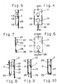
- the lock housing shown with the aid of a rod lock consists of a base part 1 with a U-shaped cross section, which is shown in FIGS. 4 and 5, and a cover part 2 according to FIGS. 6 and 7.
- the base part 1 comprises a web 11 and two legs 12, each of which is provided with a recess 13.
- a groove 14 is formed in the region of this recess 13, as shown in particular in FIG. 5.
- the web 11 is provided with a cylindrical bearing bore 15.
- the web is 11 a holding web 16 is formed with a hammer head-like end, which in the initial state lies in the same plane as the web 11.
- the cover part 2 is designed in the manner of a rectangular plate 21, which is provided with cuts 22 on two opposite edges. Between these cuts 22, a hook 23 is formed on the plate 21, which protrudes at right angles from the plate 21 and is provided with a projection 24 which corresponds to the groove 24 of the recesses 13. Finally, a receiving groove 26 is provided in an indentation 25 of the plate 21 for the retaining web 16 formed with a hammer head-like end.
- the lock housing consisting of base part 1 and cover part 2 is assembled by attaching cover part 2 with its hooks 23 to recesses 13 in legs 12 of base part 1. Since the axial extent of the hooks 23 provided with the projection 24 is smaller than the axial extent of the recesses 13, the cover part 2 can be applied in the direction perpendicular to the web 11 of the base part 1 until the plate 21 of the cover part 2 on the end faces of the legs 12 of the base part 1 rests. Such a situation is shown in FIG. 9. By a slight axial relative movement between base part 1 and cover part 2, the projections 24 formed on the hooks 23 engage in the grooves 14 of the recesses 13. The movements to be carried out for this are symbolized by the two arrows in FIG. 8.
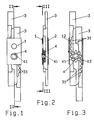
- the lock housing consisting and assembled in the manner described above, consisting of base part 1 and cover part 2, is shown as the housing of a rod lock in FIGS. 1 to 3. These figures show that such a rod lock has two drive rods 3 which can be moved in opposite directions includes. These drive rods 3 are guided in the longitudinal direction of the lock housing on guide surfaces of both the base part 1 and the cover part 2 and are supported with their mutually facing surfaces, as shown in particular in Figures 1 and 3.
- the drive rods 3 are driven by a toothed wheel 4 which engages with its teeth in rack-like tooth spaces 31 of the drive rods 3.
- the gear wheel is provided with a drive square 41 designed as a recess, in which a drive element, not shown in the drawing, engages.
- a rotation of the gear 4 causes an opposite movement of the drive rods 3, which are connected in a suitable manner with locking rods of the rod lock, not shown in the drawing.
Landscapes
- Engineering & Computer Science (AREA)
- Mechanical Engineering (AREA)
- Casings For Electric Apparatus (AREA)
- Insertion Pins And Rivets (AREA)
- Lock And Its Accessories (AREA)
- Valve-Gear Or Valve Arrangements (AREA)
- Valve Device For Special Equipments (AREA)
- High-Pressure Fuel Injection Pump Control (AREA)
- Switches With Compound Operations (AREA)
- Passenger Equipment (AREA)
- Snaps, Bayonet Connections, Set Pins, And Snap Rings (AREA)
- Pivots And Pivotal Connections (AREA)
- Toys (AREA)
Description
- Die Erfindung betrifft ein zweiteiliges Schloßgehäuse, insbesondere für Stangenschlösser mit zwei im Schloßgehäuse verschiebbar geführten Antriebsstangen, die von einem im Schloßgehäuse drehbar gelagerten, mit einem Antriebsmehrkant für ein Antriebselement versehenen Zahnrad gegenläufig antreibbar sind.
- Derartige Schloßgehäuse sind in vielen Ausführungen bekannt.
- Der Erfindung liegt die Aufgabe zugrunde, Schloßgehäuse der voranstehend beschriebenen Art derart weiterzubilden, daß sie preisgünstiger hergestellt und auf einfachere Weise montiert werden können.
- Das zur Lösung dieser Aufgabenstellung ausgebildete Schloßgehäuse ist erfindungsgemäß gekennzeichnet durch ein U-förmiges Basisteil und ein auf den Schenkeln des Basisteils aufliegendes Deckelteil, die gemeinsam Führungsflächen für die Antriebsstangen und mindestens eine zylindrische Lagerbohrung für das Zahnrad sowie mindestens eine Öffnung für das am Antriebsmehrkant angreifende Antriebselement aufweisen und die durch zwei am Deckelteil ausgebildete, jeweils in eine Aussparung in einem Schenkel des Basisteils eingreifende Haken miteinander verbindbar sind.
- Durch die erfindungsgemäße Ausbildung ergeben sich zwei auf einfache Weise, insbesondere durch Ausstanzen aus Blech herstellbare Gehäuseteile, die bereits bei ihrer Herstellung mit den Führungsflächen für die Antriebsstangen, mindestens einer Lagerbohrung für das Zahnrad und mindestens einer Öffnung für das am Antriebsmehrkant des Zahnrades angreifende Antriebselement ausgebildet sind und die auf einfache Weise durch Haken miteinander verbunden werden, die am Deckelteil ausgebildet sind und jeweils in eine Aussparung in einem Schenkel des Basisteils angreifen. Das erfindungsgemäße Schloßgehäuse besteht demgemäß aus zwei konstruktiv einfachen und preiswert herstellbaren Gehäuseteilen, die ohne zusätzliche Befestigungselemente nach dem Einlegen der Antriebsstangen und des Zahnrades mit Hilfe der erfindungsgemäßen Haken miteinander verbunden werden, so daß sich auch eine einfache und damit kostengünstige Montage ergibt.
- Gemäß einem weiteren Merkmal der Erfindung sind die Haken winkelförmig mit einem in Gehäuselängsrichtung hervorstehenden Vorsprung ausgebildet, der in eine entsprechende, in der Aussparung der Schenkel ausgebildete Nut eingreift. Diese konstruktive Gestaltung der am Deckelteil ausgebildeten Haken und der mit ihnen zusammenwirkenden Schenkel des Basisteils läßt sich kostengünstig herstellen sowie einfach montieren und ergibt eine funktionssichere Verbindung der beiden Gehäuseteile.
- Die Montage der beiden Gehäuseteile wird weiterhin dadurch vereinfacht, daß die axiale Erstreckung der Aussparungen größer als die axiale Erstreckung der mit dem Vorsprung versehenen Haken ist, so daß das mit den Haken versehene Deckelteil in senkrechter Richtung zum Steg des Basisteils auf dieses aufgesetzt werden kann, bevor die Haken in ihrer Eingriffstellung festgelegt werden. Diese in axialer Richtung erfolgende Festlegung erfolgt dadurch, daß das Deckelteil gegenüber dem Basisteil durch einen am Deckelteil oder Basisteil angeformten, mit dem jeweils anderen Teil zusammenwirkenden Haltesteg festgelegt wird. Nach dem Aufsetzen des Deckelteils auf das Basisteil und einer geringfügigen axialen Verschiebung der beiden Teile zueinander genügt somit eine Verformung des an einem der beiden Teile angebrachten Haltesteges, um die beiden Schloßgehäuseteile zuverlässig miteinander zu verbinden.
- Auf der Zeichnung ist ein Ausführungsbeispiel eines erfindungsgemäßen Schloßgehäuses dargestellt, und zwar zeigen:
- Fig. 1
- eine Draufsicht auf ein Stangenschloß,
- Fig. 2
- einen Längsschnitt durch das Stangenschloß gemäß der Schnittlinie II-II in Fig. 1,
- Fig. 3
- einen weiteren Schnitt gemäß der Schnittlinie III-III in Fig. 2,
- Fig. 4
- eine Ansicht des Basisteils,
- Fig. 5
- einen Längsschnitt durch das Basisteil gemäß der Schnittlinie V-V in Fig. 4,
- Fig. 6
- eine Ansicht des Deckelteils,
- Fig. 7
- einen Längsschnitt durch das Deckelteil gemäß der Schnittlinie VII-VII in Fig. 6,
- Fig. 8
- einen Längsschnitt durch das Basisteil und durch das Deckelteil bei Beginn der Montage,
- Fig. 9
- einen der Fig. 8 entsprechenden Längsschnitt nach dem Zusammenfügen von Basisteil und Deckelteil und
- Fig. 10
- einen weiteren Längsschnitt gemäß den Figuren 8 und 9 mit relativ zueinander festgelegten Teilen.
- Das anhand eines Stangenschlosses dargestellte Schloßgehäuse besteht aus einem im Querschnitt U-förmigen Basisteil 1, das in den Figuren 4 und 5 dargestellt ist, und einem Deckelteil 2 gemäß den Figuren 6 und 7.
- Das Basisteil 1 umfaßt einen Steg 11 und zwei Schenkel 12, die jeweils mit einer Ausnehmung 13 versehen sind. Im Bereich dieser Ausnehmung 13 ist eine Nut 14 ausgebildet, wie insbesondere Fig. 5 zeigt. Der Steg 11 ist mit einer zylindrischen Lagerbohrung 15 versehen. Schließlich ist an den Steg 11 ein Haltesteg 16 mit einem hammerkopfartigen Ende angeformt, der im Ausgangszustand in derselben Ebene wie der Steg 11 liegt.
- Das Deckelteil 2 ist in der Art einer rechteckigen Platte 21 ausgeführt, die an zwei gegenüberliegenden Rändern mit Einschnitten 22 versehen ist. Zwischen diesen Einschnitten 22 ist an die Platte 21 ein Haken 23 angeformt, der rechtwinklig von der Platte 21 absteht und mit einem Vorsprung 24 versehen ist, der der Nut 24 der Aussparungen 13 entspricht. Schließlich ist in einer Einprägung 25 der Platte 21 eine Aufnahmenut 26 für den mit einem hammerkopfartigen Ende ausgebildeten Haltesteg 16 vorgesehen.
- Wie am besten den Figuren 8 bis 10 zu entnehmen ist, erfolgt die Montage des aus Basisteil 1 und Deckelteil 2 bestehenden Schloßgehäuses dadurch, daß das Deckelteil 2 mit seinen Haken 23 an die Aussparungen 13 in den Schenkeln 12 des Basisteils 1 angesetzt wird. Da die axiale Erstreckung der mit dem Vorsprung 24 versehenen Haken 23 kleiner ist als die axiale Erstreckung der Aussparungen 13, kann das Deckelteil 2 in senkrechter Richtung zum Steg 11 des Basisteils 1 angesetzt werden, bis die Platte 21 des Deckelteils 2 auf den Stirnflächen der Schenkel 12 des Basisteils 1 aufliegt. Eine derartige Situation ist in Fig. 9 dargestellt. Durch eine geringfügige axiale Relativbewegung zwischen Basisteil 1 und Deckelteil 2 greifen die an den Haken 23 ausgebildeten Vorsprünge 24 in die Nuten 14 der Aussparungen 13 ein. Die hierfür auszuführenden Bewegungen sind durch die beiden Pfeile in Fig. 8 symbolisiert.
- Um die gemäß Fig. 9 zusammengefügten Schloßgehäuseteile in dieser Stellung festzuhalten, wird gemäß dem Pfeil in Fig. 9 der Haltesteg 16 des Basisteils um 90° abgebogen, so daß sein hammerkopfartiges Ende in die Aufnahmenut 26 der Einprägung 25 des Deckelteils 2 eingreift. Diese Montageendstellung des Schloßgehäuses ist in Fig. 10 gezeichnet.
- Das auf die voranstehend beschriebene Weise aus Basisteil 1 und Deckelteil 2 bestehende und montierte Schloßgehäuse ist als Gehäuse eines Stangenschlosses in den Figuren 1 bis 3 dargestellt. Diese Figuren zeigen, daß ein derartiges Stangenschloß zwei gegenläufig bewegbare Antriebsstangen 3 umfaßt. Diese Antriebsstangen 3 sind in Längsrichtung des Schloßgehäuses verschiebbar an Führungsflächen sowohl des Basisteils 1 als auch des Deckelteils 2 geführt und stützen sich mit ihren zueinanderweisenden Flächen gegeneinander ab, wie insbesondere die Figuren 1 und 3 zeigen.
- Der Antrieb der Antriebsstangen 3 erfolgt durch ein Zahnrad 4, das mit seinen Zähnen in zahnstangenartige Zahnlücken 31 der Antriebsstangen 3 eingreift. Das Zahnrad ist mit einem als Aussparung ausgebildeten Antriebsvierkant 41 versehen, in den ein auf der Zeichnung nicht dargestelltes Antriebselement eingreift. Wie insbesondere aus Fig. 3 hervorgeht, bewirkt eine Verdrehung des Zahnrades 4 eine gegenläufige Bewegung der Antriebsstangen 3, die in geeigneter Weise mit auf der Zeichnung nicht dargestellten Verriegelungsstangen des Stangenschlosses verbunden werden.
-
- 1
- Basisteil
- 11
- Steg
- 12
- Schenkel
- 13
- Aussparung
- 14
- Nut
- 15
- Lagerbohrung
- 16
- Haltesteg
- 2
- Deckelteil
- 21
- Platte
- 22
- Einschnitt
- 23
- Haken
- 24
- Vorsprung
- 25
- Einprägung
- 26
- Aufnahmenut
- 3
- Antriebsstange
- 31
- Zahnlücke
- 4
- Zahnrad
- 41
- Antriebsvierkant
Claims (4)
- Zweiteiliges Schloßgehäuse, insbesondere für Stangenschlösser mit zwei im Schloßgehäuse verschiebbar geführten Antriebsstangen, die von einem im Schloßgehäuse drehbar gelagerten, mit einem Antriebsmehrkant für ein Antriebselement versehenen Zahnrad gegenläufig antreibbar sind,
gekennzeichnet durch
ein U-förmiges Basisteil (1) und ein auf den Schenkeln (12) des Basisteils (1) aufliegendes Deckelteil (2), die gemeinsam Führungsflächen für die Antriebsstangen (3) und mindestens eine zylindrische Lagerbohrung (15) für das Zahnrad (4) sowie mindestens eine Öffnung für das am Antriebsmehrkant (41) angreifende Antriebselement aufweisen und die durch zwei am Deckelteil (2) ausgebildete, jeweils in eine Aussparung (13) in einem Schenkel (12) des Basisteils (1) eingreifende Haken (23) miteinander verbindbar sind. - Schloßgehäuse nach Anspruch 1, dadurch gekennzeichnet, daß die Haken (23) winkelförmig mit einem in Gehäuselängsrichtung hervorstehenden Vorsprung (24) ausgebildet sind, der in eine entsprechende, in der Aussparung (13) der Schenkel (12) ausgebildete Nut (14) eingreift.
- Schloßgehäuse nach Anspruch 1 und 2, dadurch gekennzeichnet, daß die axiale Erstreckung der Aussparungen (13) größer als die axiale Erstreckung der mit dem Vorsprung (24) versehenen Haken (23) ist und die Haken (23) in ihrer Eingriffstellung in axialer Richtung festlegbar sind.
- Schloßgehäuse nach Anspruch 3, dadurch gekennzeichnet, daß das Deckelteil (2) gegenüber dem Basisteil (1) durch einen am Deckelteil (2) oder Basisteil (1) angeformten, mit dem jeweils anderen Teil zusammenwirkenden Haltesteg (16) festlegbar ist.
Applications Claiming Priority (2)
| Application Number | Priority Date | Filing Date | Title |
|---|---|---|---|
| DE4403440 | 1994-02-04 | ||
| DE4403440A DE4403440C2 (de) | 1994-02-04 | 1994-02-04 | Verschlußgehäuse |
Publications (3)
| Publication Number | Publication Date |
|---|---|
| EP0666392A1 EP0666392A1 (de) | 1995-08-09 |
| EP0666392B1 true EP0666392B1 (de) | 1997-11-19 |
| EP0666392B2 EP0666392B2 (de) | 2001-03-21 |
Family
ID=6509456
Family Applications (1)
| Application Number | Title | Priority Date | Filing Date |
|---|---|---|---|
| EP95101042A Expired - Lifetime EP0666392B2 (de) | 1994-02-04 | 1995-01-26 | Schlossgehäuse |
Country Status (5)
| Country | Link |
|---|---|
| EP (1) | EP0666392B2 (de) |
| AT (1) | ATE160415T1 (de) |
| DE (2) | DE4403440C2 (de) |
| DK (1) | DK0666392T3 (de) |
| ES (1) | ES2111344T3 (de) |
Families Citing this family (4)
| Publication number | Priority date | Publication date | Assignee | Title |
|---|---|---|---|---|
| DE19911894A1 (de) * | 1999-03-17 | 2000-09-28 | Siegenia Frank Kg | Kantengetriebe |
| FR2798949B1 (fr) * | 1999-09-28 | 2001-10-26 | Ferco Int Usine Ferrures | Menuiserie de type porte ou fenetre |
| GB2582888B (en) * | 2018-11-29 | 2023-04-26 | Era Home Security Ltd | Espagnolette Lock |
| CN110924770A (zh) * | 2019-12-17 | 2020-03-27 | 上海硒米安防科技有限公司 | 大行程锁具 |
Family Cites Families (9)
| Publication number | Priority date | Publication date | Assignee | Title |
|---|---|---|---|---|
| GB626257A (en) * | 1947-08-19 | 1949-07-12 | Jabez Ash | Improvements in locks |
| FR1217232A (fr) * | 1958-12-05 | 1960-05-02 | Perfectionnement apporté aux serrures | |
| DE6923021U (de) * | 1969-06-09 | 1969-10-30 | Heinrich Strenger Fa | Kantengetriebe |
| DE2345496A1 (de) * | 1973-09-08 | 1975-03-20 | Siegenia Frank Kg | Treibstangenbeschlag, insbesondere einsteck-kantengetriebe, fuer die fluegel von fenstern, tueren od. dgl |
| AU518869B2 (en) * | 1977-07-19 | 1981-10-22 | Lowe & Fletcher Australia Pty Ltd | Improved lock structure |
| GB2148377B (en) * | 1983-10-22 | 1987-02-18 | Hardware & Systems Patents Ltd | Improvements in fasteners for doors, windows and the like |
| DE3407700C2 (de) * | 1984-03-02 | 1986-10-30 | Rittal-Werk Rudolf Loh Gmbh & Co Kg, 6348 Herborn | Abschließbare Handhabe für Schaltschranktüren und dgl. |
| DE3718173A1 (de) * | 1987-05-29 | 1988-12-22 | Siegenia Frank Kg | Treibstangengetriebe fuer fenster, tueren od. dgl. |
| DE9212950U1 (de) * | 1992-09-25 | 1992-12-03 | Siegenia-Frank Kg, 5900 Siegen | Treibstangenbeschlag für Fenster, Türen o.dgl. |
-
1994
- 1994-02-04 DE DE4403440A patent/DE4403440C2/de not_active Expired - Fee Related
-
1995
- 1995-01-26 DK DK95101042T patent/DK0666392T3/da active
- 1995-01-26 EP EP95101042A patent/EP0666392B2/de not_active Expired - Lifetime
- 1995-01-26 DE DE59500992T patent/DE59500992D1/de not_active Expired - Fee Related
- 1995-01-26 AT AT95101042T patent/ATE160415T1/de not_active IP Right Cessation
- 1995-01-26 ES ES95101042T patent/ES2111344T3/es not_active Expired - Lifetime
Also Published As
| Publication number | Publication date |
|---|---|
| ES2111344T3 (es) | 1998-03-01 |
| EP0666392A1 (de) | 1995-08-09 |
| DK0666392T3 (da) | 1998-07-27 |
| DE4403440C1 (de) | 1995-11-09 |
| DE4403440C2 (de) | 1999-09-23 |
| DE59500992D1 (de) | 1998-01-02 |
| ATE160415T1 (de) | 1997-12-15 |
| EP0666392B2 (de) | 2001-03-21 |
Similar Documents
| Publication | Publication Date | Title |
|---|---|---|
| EP1290303B1 (de) | Stangenschloss für ein verschlusssystem | |
| EP0412338B1 (de) | Gestell aus lösbar durch einen Verbinder miteinander kuppelbaren Profilstangen | |
| DE2738672A1 (de) | Fensterheber, insbesondere fuer kraftfahrzeuge | |
| EP0589170B1 (de) | Treibstangenbeschlag für Fenster, Türen od. dgl. | |
| EP0666392B1 (de) | Schlossgehäuse | |
| EP0674859A2 (de) | Verschluss für Schmuckteile | |
| DE69200617T2 (de) | Verriegelung mit entkuppelbarem Rotor. | |
| EP0665353A1 (de) | Stangenschloss | |
| EP0329064B1 (de) | Gefäss mit einem mit diesem verbindbaren Griffkörper | |
| EP0575570B1 (de) | Armbanduhr | |
| DE3009704A1 (de) | Vorrichtung zur gelenkigen halterung eines scheibenwischer-wischblattes an einem wischarm | |
| EP0178369A2 (de) | Verbindungselement | |
| EP0717204A1 (de) | Sicherheitsbolzen, der in Durchgangslöcher von Bauteilen bis zu einem Anschlag einschiebbar ist | |
| DE19702251C2 (de) | Zentralverriegelungsstellelement für Türen oder Klappen von Kraftfahrzeugen | |
| DE3435208A1 (de) | Verschluss zum verbinden der beiden enden eines guertels | |
| DE19756728A1 (de) | Spielfreies Hebelgelenk | |
| AT524575B1 (de) | Träger für einen Aktuator mit einem Halteelement | |
| EP0522337B1 (de) | Vorrichtung zum Verbinden und Verriegeln zweier Elemente | |
| DE1559771B2 (de) | Eckumlenker für die Betätigungsund Verriegelungsgetriebe bei Fenstern, Türen od.dgl | |
| DE3120545A1 (de) | Werkzeug zur montage von sicherungsklemmen und sicherungsklemme | |
| DE3602263A1 (de) | Scheinwerfer fuer fahrzeuge, insbesondere fuer kraftfahrzeuge | |
| DE3035800A1 (de) | Rastvorrichtung fuer fensterdrehgriff | |
| DE10133330B4 (de) | Endstück für Stäbe eines Rolltorpanzers | |
| DE2717293A1 (de) | Elektromagnetisches relais mit zwangsgefuehrten kontakten | |
| DE4230476A1 (de) | Fenster- oder Türbeschlag |
Legal Events
| Date | Code | Title | Description |
|---|---|---|---|
| PUAI | Public reference made under article 153(3) epc to a published international application that has entered the european phase |
Free format text: ORIGINAL CODE: 0009012 |
|
| AK | Designated contracting states |
Kind code of ref document: A1 Designated state(s): AT BE CH DE DK ES FR GB GR IE IT LI LU NL PT SE |
|
| RAX | Requested extension states of the european patent have changed |
Free format text: SI |
|
| 17P | Request for examination filed |
Effective date: 19950807 |
|
| RBV | Designated contracting states (corrected) |
Designated state(s): AT BE CH DE DK ES FR GB GR IE IT LI LU NL PT SE |
|
| GRAG | Despatch of communication of intention to grant |
Free format text: ORIGINAL CODE: EPIDOS AGRA |
|
| GRAH | Despatch of communication of intention to grant a patent |
Free format text: ORIGINAL CODE: EPIDOS IGRA |
|
| 17Q | First examination report despatched |
Effective date: 19970502 |
|
| GRAH | Despatch of communication of intention to grant a patent |
Free format text: ORIGINAL CODE: EPIDOS IGRA |
|
| GRAA | (expected) grant |
Free format text: ORIGINAL CODE: 0009210 |
|
| AK | Designated contracting states |
Kind code of ref document: B1 Designated state(s): AT BE CH DE DK ES FR GB GR IE IT LI LU NL PT SE |
|
| AX | Request for extension of the european patent |
Free format text: SI |
|
| PG25 | Lapsed in a contracting state [announced via postgrant information from national office to epo] |
Ref country code: GR Free format text: LAPSE BECAUSE OF FAILURE TO SUBMIT A TRANSLATION OF THE DESCRIPTION OR TO PAY THE FEE WITHIN THE PRESCRIBED TIME-LIMIT Effective date: 19971119 |
|
| REF | Corresponds to: |
Ref document number: 160415 Country of ref document: AT Date of ref document: 19971215 Kind code of ref document: T |
|
| REG | Reference to a national code |
Ref country code: CH Ref legal event code: NV Representative=s name: E. BLUM & CO. PATENTANWAELTE Ref country code: CH Ref legal event code: EP |
|
| GBT | Gb: translation of ep patent filed (gb section 77(6)(a)/1977) |
Effective date: 19971119 |
|
| ET | Fr: translation filed | ||
| REF | Corresponds to: |
Ref document number: 59500992 Country of ref document: DE Date of ref document: 19980102 |
|
| ITF | It: translation for a ep patent filed | ||
| REG | Reference to a national code |
Ref country code: ES Ref legal event code: FG2A Ref document number: 2111344 Country of ref document: ES Kind code of ref document: T3 |
|
| REG | Reference to a national code |
Ref country code: PT Ref legal event code: SC4A Free format text: AVAILABILITY OF NATIONAL TRANSLATION Effective date: 19980128 |
|
| REG | Reference to a national code |
Ref country code: DK Ref legal event code: T3 |
|
| PLBI | Opposition filed |
Free format text: ORIGINAL CODE: 0009260 |
|
| PLBF | Reply of patent proprietor to notice(s) of opposition |
Free format text: ORIGINAL CODE: EPIDOS OBSO |
|
| 26 | Opposition filed |
Opponent name: SIEGENIA-FRANK KG Effective date: 19980803 |
|
| NLR1 | Nl: opposition has been filed with the epo |
Opponent name: SIEGENIA-FRANK KG |
|
| PLBF | Reply of patent proprietor to notice(s) of opposition |
Free format text: ORIGINAL CODE: EPIDOS OBSO |
|
| PLBF | Reply of patent proprietor to notice(s) of opposition |
Free format text: ORIGINAL CODE: EPIDOS OBSO |
|
| PGFP | Annual fee paid to national office [announced via postgrant information from national office to epo] |
Ref country code: GB Payment date: 19991213 Year of fee payment: 6 |
|
| PGFP | Annual fee paid to national office [announced via postgrant information from national office to epo] |
Ref country code: IE Payment date: 19991214 Year of fee payment: 6 |
|
| PGFP | Annual fee paid to national office [announced via postgrant information from national office to epo] |
Ref country code: CH Payment date: 19991217 Year of fee payment: 6 |
|
| PGFP | Annual fee paid to national office [announced via postgrant information from national office to epo] |
Ref country code: DK Payment date: 19991221 Year of fee payment: 6 Ref country code: AT Payment date: 19991221 Year of fee payment: 6 |
|
| PGFP | Annual fee paid to national office [announced via postgrant information from national office to epo] |
Ref country code: PT Payment date: 19991222 Year of fee payment: 6 |
|
| PGFP | Annual fee paid to national office [announced via postgrant information from national office to epo] |
Ref country code: LU Payment date: 19991223 Year of fee payment: 6 |
|
| PGFP | Annual fee paid to national office [announced via postgrant information from national office to epo] |
Ref country code: ES Payment date: 20000126 Year of fee payment: 6 |
|
| PLAW | Interlocutory decision in opposition |
Free format text: ORIGINAL CODE: EPIDOS IDOP |
|
| PLAW | Interlocutory decision in opposition |
Free format text: ORIGINAL CODE: EPIDOS IDOP |
|
| PG25 | Lapsed in a contracting state [announced via postgrant information from national office to epo] |
Ref country code: LU Free format text: LAPSE BECAUSE OF NON-PAYMENT OF DUE FEES Effective date: 20010126 Ref country code: IE Free format text: LAPSE BECAUSE OF NON-PAYMENT OF DUE FEES Effective date: 20010126 Ref country code: GB Free format text: LAPSE BECAUSE OF NON-PAYMENT OF DUE FEES Effective date: 20010126 Ref country code: AT Free format text: LAPSE BECAUSE OF NON-PAYMENT OF DUE FEES Effective date: 20010126 |
|
| PG25 | Lapsed in a contracting state [announced via postgrant information from national office to epo] |
Ref country code: ES Free format text: LAPSE BECAUSE OF NON-PAYMENT OF DUE FEES Effective date: 20010127 |
|
| PG25 | Lapsed in a contracting state [announced via postgrant information from national office to epo] |
Ref country code: LI Free format text: LAPSE BECAUSE OF NON-PAYMENT OF DUE FEES Effective date: 20010131 Ref country code: CH Free format text: LAPSE BECAUSE OF NON-PAYMENT OF DUE FEES Effective date: 20010131 |
|
| PUAH | Patent maintained in amended form |
Free format text: ORIGINAL CODE: 0009272 |
|
| STAA | Information on the status of an ep patent application or granted ep patent |
Free format text: STATUS: PATENT MAINTAINED AS AMENDED |
|
| 27A | Patent maintained in amended form |
Effective date: 20010321 |
|
| AK | Designated contracting states |
Kind code of ref document: B2 Designated state(s): AT BE CH DE DK ES FR GB GR IE IT LI LU NL PT SE |
|
| REG | Reference to a national code |
Ref country code: CH Ref legal event code: AEN Free format text: AUFRECHTERHALTUNG DES PATENTES IN GEAENDERTER FORM |
|
| NLR2 | Nl: decision of opposition | ||
| ET3 | Fr: translation filed ** decision concerning opposition | ||
| PG25 | Lapsed in a contracting state [announced via postgrant information from national office to epo] |
Ref country code: DK Free format text: LAPSE BECAUSE OF FAILURE TO SUBMIT A TRANSLATION OF THE DESCRIPTION OR TO PAY THE FEE WITHIN THE PRESCRIBED TIME-LIMIT Effective date: 20010621 |
|
| NLR3 | Nl: receipt of modified translations in the netherlands language after an opposition procedure | ||
| GBPC | Gb: european patent ceased through non-payment of renewal fee |
Effective date: 20010126 |
|
| REG | Reference to a national code |
Ref country code: CH Ref legal event code: PL |
|
| PG25 | Lapsed in a contracting state [announced via postgrant information from national office to epo] |
Ref country code: PT Free format text: LAPSE BECAUSE OF FAILURE TO SUBMIT A TRANSLATION OF THE DESCRIPTION OR TO PAY THE FEE WITHIN THE PRESCRIBED TIME-LIMIT Effective date: 20010928 |
|
| REG | Reference to a national code |
Ref country code: PT Ref legal event code: MP4A Effective date: 20010621 |
|
| REG | Reference to a national code |
Ref country code: IE Ref legal event code: MM4A |
|
| PGFP | Annual fee paid to national office [announced via postgrant information from national office to epo] |
Ref country code: DE Payment date: 20011221 Year of fee payment: 8 |
|
| PGFP | Annual fee paid to national office [announced via postgrant information from national office to epo] |
Ref country code: FR Payment date: 20011226 Year of fee payment: 8 |
|
| PGFP | Annual fee paid to national office [announced via postgrant information from national office to epo] |
Ref country code: NL Payment date: 20011227 Year of fee payment: 8 |
|
| PGFP | Annual fee paid to national office [announced via postgrant information from national office to epo] |
Ref country code: SE Payment date: 20020102 Year of fee payment: 8 |
|
| PGFP | Annual fee paid to national office [announced via postgrant information from national office to epo] |
Ref country code: BE Payment date: 20020220 Year of fee payment: 8 |
|
| REG | Reference to a national code |
Ref country code: ES Ref legal event code: FD2A Effective date: 20021016 |
|
| PG25 | Lapsed in a contracting state [announced via postgrant information from national office to epo] |
Ref country code: SE Free format text: LAPSE BECAUSE OF NON-PAYMENT OF DUE FEES Effective date: 20030127 |
|
| PG25 | Lapsed in a contracting state [announced via postgrant information from national office to epo] |
Ref country code: BE Free format text: LAPSE BECAUSE OF NON-PAYMENT OF DUE FEES Effective date: 20030131 |
|
| PG25 | Lapsed in a contracting state [announced via postgrant information from national office to epo] |
Ref country code: NL Free format text: LAPSE BECAUSE OF NON-PAYMENT OF DUE FEES Effective date: 20030801 Ref country code: DE Free format text: LAPSE BECAUSE OF NON-PAYMENT OF DUE FEES Effective date: 20030801 |
|
| EUG | Se: european patent has lapsed | ||
| PG25 | Lapsed in a contracting state [announced via postgrant information from national office to epo] |
Ref country code: FR Free format text: LAPSE BECAUSE OF NON-PAYMENT OF DUE FEES Effective date: 20030930 |
|
| NLV4 | Nl: lapsed or anulled due to non-payment of the annual fee |
Effective date: 20030801 |
|
| REG | Reference to a national code |
Ref country code: FR Ref legal event code: ST |
|
| PG25 | Lapsed in a contracting state [announced via postgrant information from national office to epo] |
Ref country code: IT Free format text: LAPSE BECAUSE OF NON-PAYMENT OF DUE FEES;WARNING: LAPSES OF ITALIAN PATENTS WITH EFFECTIVE DATE BEFORE 2007 MAY HAVE OCCURRED AT ANY TIME BEFORE 2007. THE CORRECT EFFECTIVE DATE MAY BE DIFFERENT FROM THE ONE RECORDED. Effective date: 20050126 |
|
| PG25 | Lapsed in a contracting state [announced via postgrant information from national office to epo] |
Ref country code: PT Free format text: LAPSE BECAUSE OF FAILURE TO SUBMIT A TRANSLATION OF THE DESCRIPTION OR TO PAY THE FEE WITHIN THE PRESCRIBED TIME-LIMIT Effective date: 20010126 |