EP0660397B1 - Siliziumnitridteil mit hoher Wärmeleitfähigkeit, Halbleitergehäuse, Heizung und thermischer Kopf - Google Patents
Siliziumnitridteil mit hoher Wärmeleitfähigkeit, Halbleitergehäuse, Heizung und thermischer Kopf Download PDFInfo
- Publication number
- EP0660397B1 EP0660397B1 EP94120716A EP94120716A EP0660397B1 EP 0660397 B1 EP0660397 B1 EP 0660397B1 EP 94120716 A EP94120716 A EP 94120716A EP 94120716 A EP94120716 A EP 94120716A EP 0660397 B1 EP0660397 B1 EP 0660397B1
- Authority
- EP
- European Patent Office
- Prior art keywords
- silicon nitride
- grain boundary
- sintered body
- boundary phase
- less
- Prior art date
- Legal status (The legal status is an assumption and is not a legal conclusion. Google has not performed a legal analysis and makes no representation as to the accuracy of the status listed.)
- Expired - Lifetime
Links
Images


Classifications
-
- H10W76/17—
-
- H—ELECTRICITY
- H05—ELECTRIC TECHNIQUES NOT OTHERWISE PROVIDED FOR
- H05B—ELECTRIC HEATING; ELECTRIC LIGHT SOURCES NOT OTHERWISE PROVIDED FOR; CIRCUIT ARRANGEMENTS FOR ELECTRIC LIGHT SOURCES, IN GENERAL
- H05B3/00—Ohmic-resistance heating
- H05B3/10—Heating elements characterised by the composition or nature of the materials or by the arrangement of the conductor
- H05B3/12—Heating elements characterised by the composition or nature of the materials or by the arrangement of the conductor characterised by the composition or nature of the conductive material
- H05B3/14—Heating elements characterised by the composition or nature of the materials or by the arrangement of the conductor characterised by the composition or nature of the conductive material the material being non-metallic
- H05B3/148—Silicon, e.g. silicon carbide, magnesium silicide, heating transistors or diodes
-
- C—CHEMISTRY; METALLURGY
- C04—CEMENTS; CONCRETE; ARTIFICIAL STONE; CERAMICS; REFRACTORIES
- C04B—LIME, MAGNESIA; SLAG; CEMENTS; COMPOSITIONS THEREOF, e.g. MORTARS, CONCRETE OR LIKE BUILDING MATERIALS; ARTIFICIAL STONE; CERAMICS; REFRACTORIES; TREATMENT OF NATURAL STONE
- C04B35/00—Shaped ceramic products characterised by their composition; Ceramics compositions; Processing powders of inorganic compounds preparatory to the manufacturing of ceramic products
- C04B35/515—Shaped ceramic products characterised by their composition; Ceramics compositions; Processing powders of inorganic compounds preparatory to the manufacturing of ceramic products based on non-oxide ceramics
- C04B35/58—Shaped ceramic products characterised by their composition; Ceramics compositions; Processing powders of inorganic compounds preparatory to the manufacturing of ceramic products based on non-oxide ceramics based on borides, nitrides, i.e. nitrides, oxynitrides, carbonitrides or oxycarbonitrides or silicides
- C04B35/584—Shaped ceramic products characterised by their composition; Ceramics compositions; Processing powders of inorganic compounds preparatory to the manufacturing of ceramic products based on non-oxide ceramics based on borides, nitrides, i.e. nitrides, oxynitrides, carbonitrides or oxycarbonitrides or silicides based on silicon nitride
- C04B35/593—Shaped ceramic products characterised by their composition; Ceramics compositions; Processing powders of inorganic compounds preparatory to the manufacturing of ceramic products based on non-oxide ceramics based on borides, nitrides, i.e. nitrides, oxynitrides, carbonitrides or oxycarbonitrides or silicides based on silicon nitride obtained by pressure sintering
- C04B35/5935—Shaped ceramic products characterised by their composition; Ceramics compositions; Processing powders of inorganic compounds preparatory to the manufacturing of ceramic products based on non-oxide ceramics based on borides, nitrides, i.e. nitrides, oxynitrides, carbonitrides or oxycarbonitrides or silicides based on silicon nitride obtained by pressure sintering obtained by gas pressure sintering
-
- F—MECHANICAL ENGINEERING; LIGHTING; HEATING; WEAPONS; BLASTING
- F16—ENGINEERING ELEMENTS AND UNITS; GENERAL MEASURES FOR PRODUCING AND MAINTAINING EFFECTIVE FUNCTIONING OF MACHINES OR INSTALLATIONS; THERMAL INSULATION IN GENERAL
- F16C—SHAFTS; FLEXIBLE SHAFTS; ELEMENTS OR CRANKSHAFT MECHANISMS; ROTARY BODIES OTHER THAN GEARING ELEMENTS; BEARINGS
- F16C33/00—Parts of bearings; Special methods for making bearings or parts thereof
- F16C33/02—Parts of sliding-contact bearings
- F16C33/04—Brasses; Bushes; Linings
- F16C33/043—Sliding surface consisting mainly of ceramics, cermets or hard carbon, e.g. diamond like carbon [DLC]
-
- H—ELECTRICITY
- H05—ELECTRIC TECHNIQUES NOT OTHERWISE PROVIDED FOR
- H05B—ELECTRIC HEATING; ELECTRIC LIGHT SOURCES NOT OTHERWISE PROVIDED FOR; CIRCUIT ARRANGEMENTS FOR ELECTRIC LIGHT SOURCES, IN GENERAL
- H05B3/00—Ohmic-resistance heating
- H05B3/10—Heating elements characterised by the composition or nature of the materials or by the arrangement of the conductor
- H05B3/12—Heating elements characterised by the composition or nature of the materials or by the arrangement of the conductor characterised by the composition or nature of the conductive material
- H05B3/14—Heating elements characterised by the composition or nature of the materials or by the arrangement of the conductor characterised by the composition or nature of the conductive material the material being non-metallic
- H05B3/141—Conductive ceramics, e.g. metal oxides, metal carbides, barium titanate, ferrites, zirconia, vitrous compounds
- H05B3/143—Conductive ceramics, e.g. metal oxides, metal carbides, barium titanate, ferrites, zirconia, vitrous compounds applied to semiconductors, e.g. wafers heating
-
- H10W40/259—
-
- H10W70/692—
-
- H10W72/00—
-
- H10W74/117—
-
- F—MECHANICAL ENGINEERING; LIGHTING; HEATING; WEAPONS; BLASTING
- F16—ENGINEERING ELEMENTS AND UNITS; GENERAL MEASURES FOR PRODUCING AND MAINTAINING EFFECTIVE FUNCTIONING OF MACHINES OR INSTALLATIONS; THERMAL INSULATION IN GENERAL
- F16C—SHAFTS; FLEXIBLE SHAFTS; ELEMENTS OR CRANKSHAFT MECHANISMS; ROTARY BODIES OTHER THAN GEARING ELEMENTS; BEARINGS
- F16C2360/00—Engines or pumps
- F16C2360/23—Gas turbine engines
- F16C2360/24—Turbochargers
-
- H10W70/682—
-
- H10W70/685—
-
- H10W72/5363—
-
- H10W72/884—
-
- H10W74/00—
-
- H10W90/734—
-
- H10W90/754—
-
- H10W90/756—
Definitions
- the present invention relates to a high thermal conductive silicon nitride structural member, i.e. application parts using high thermal conductive silicon nitride, such as a semiconductor package, a heater and a thermal head. More particularly, the semiconductor package is superior in mechanical structural strength and heat releasing.
- the heater includes a heating resistor disposed on the surface of or within a sintered body of high thermal conductive silicon nitride, and is superior particularly in mechanical strength and thermal response for ON-OFF control of a voltage applied to the heating resistor.
- the thermal head is superior in high-speed printing with fine accuracy.
- EP-A-0 587 119 is a document in the sense of Art. 54 (3) EPC and discloses a high thermal conductive silicon nitride sintered body and a method of producing same.
- the high thermal conductive silicon nitride sintered body contains: 2,0 - 7,5 % by weight of a rare earth element in terms of the amount of an oxide thereof; at most 0,3 % by weight of Li, Na, K, Fe, Ca, Mg, Sr, Ba, Mn and B as impurity cationic elements in terms of total amount thereof; and, if necessary, at most 2,0 % by weight of alumina and/or at most 2,0 % by weight of aluminum nitride, and comprises a beta-phase type silicon nitride crystal and a grain boundary phase.
- the silicon nitride sintered body has a thermal conductivity of at least 60 W/m ⁇ K.
- the sintered body further contains 0,2 - 3,0 % by weight of at least one compound selected from the group consisting of the oxides, carbides, nitrides, silicides and borides of Ti, Zr, Hf, V, Nb, Ta, Cr, Mo and W.
- the sintered body has a porosity of at most 1,5 % by volume, a thermal conductivity of at least 60 W/m ⁇ K, and a three-point bending strength of at least 80 kg/mm 2 at a room temperature.
- the sintered body achieves high thermal conductivity and good heat-radiating characteristics, as well as the high-strength characteristics generally inherent in silicon nitride sintered bodies.
- EP-A-0 438 897 discloses a silicon nitride body having grain boundaries of Si 3 N 4 of not more than a specific value.
- the silicon nitride body may contain Al of not more than 0,3 wt % when calculated as oxide.
- the thermal conductivity of the sintered body is not less than 0,15 cal/cm x sec. °C.
- a ceramic sintered body containing silicon nitride as a primary component is generally highly resistant against heat even under environment at high temperature over 1000 °C and also highly resistant against thermal shocks, its application as a high-temperature structural part material instead of a conventional heat-resistant super alloy to various high-strength and heat-resistant parts, such as gas turbine parts, engine parts and mechanical parts for steel manufacture, has been attempted. Also, such a ceramic sintered body has good corrosion resistance against metals and, therefore, its application as a melt-resistant material for molten metals has been tried. Further, such a ceramic sintered body has good wear resistance and, therefore, its application to sliding members, such as bearings, and cutting tools has been practiced.
- composition of the ceramic sintered body of silicon nitride it is conventionally known to add, as a sintering assistant agent, at least one oxide of rare-earth elements or alkaline rare-earth elements, such as yttrium oxide (Y 2 O 3 ), cerium oxide (CeO) and calcium oxide (CaO), to silicon nitride.
- a sintering assistant agent serves to enhance a sintering process so as to increase a degree of compactness (density) and strength.
- the conventional sintered body of silicon nitride is manufactured by adding the above sintering assistant agent to silicon nitride powder to prepare a material mixture, pressing the mixture into a compact, baking the pressed compact in a baking furnace for a predetermined period of time at temperature in the range of 1600 to 1850 °C, cooling the baked compact by stopping power supplied to the furnace, and machining the resultant sintered body into a product by cutting and grinding.
- the sintered body of silicon nitride manufactured by the above conventional method is superior in mechanical strength represented by deflective strength, rupture toughness, etc., and also has the small coefficient of thermal expansion.
- its thermal conductivity is as low as 20 to 30 W/(m ⁇ K) and its heat releasing is remarkably inferior to other sintered bodies of aluminum nitride (AlN), beryllium oxide (BeO), silicon carbide (SiC), etc. It has therefore been difficult to employ the conventional sintered body of silicon nitride as electronic materials of, e.g., substrates for semiconductor packages, and as substrates for heaters, which particularly require a high ability of heat releasing.
- the sintered body of aluminum nitride has the higher thermal conductivity and the lower coefficient of thermal expansion than other kinds of sintered bodies, its use has become more prevalent as a material for circuit board parts, substrates and enclosures of semiconductor packages, etc. which are more and more increasing in speed, output power, function, as well as size.
- the sintered body of aluminum nitride which is sufficiently satisfactory in mechanical strength has not been obtained so far. Its stability (e.g., oxidation resistance) at high temperature is also not sufficient.
- a semiconductor package using a substrate formed of the sintered body of aluminum nitride is apt to break due to the thermal stress caused upon heating under energization or deficiency in the substrate strength when it is fixed to a mount board. Accordingly, semiconductor packages are also required to have not only a satisfactory characteristic of mechanical strength enough to endure thermal stresses, shocks, etc., but also a superior characteristic of heat releasing enough to be adaptable for higher output power and an increased amount of heat generated.
- a thermal heater is fabricated by forming a linear heating resistor, which has any desired width and length, on a ceramic substrate by pattern printing, or installing the resistor within the substrate, and it is widely utilized as parts of glow plugs for diesel engines, thermal heads and so forth.
- a thermal head comprising a heater formed of a heating resistor, electric leads and a wear-resistant layer, these members being all formed on a ceramic substrate, is employed in a variety of printing equipment.
- various thermal heads are used to convert information sent to those devices in the form of electric signals into an image of letters, symbols or figures on heat-sensitive recording paper.
- the thermal head has a heating resistor to heat chemical materials which are coated on the heat-sensitive recording paper and develop a color upon heating, enabling characters and/or images to be thermally formed on the paper.
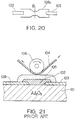
- a thermal head for use as a recording unit of conventional thick-film type thermal printers generally has a basic construction as shown in Fig. 21.
- the thermal head comprises a ceramic substrate 101 made of alumina (Al 2 O 3 ), a heating resistor 102 formed on the substrate 101 for generating heat upon application of a voltage, electric leads 103 connected to respective ends of the heating resistor 102 in opposite relation, and a wear-resistant layer 105 for protecting the heating resistor 102 and the electric leads 103 against their wears caused by contact with heat-sensitive recording paper 104.
- the heat-sensitive recording paper 104 is brought into pressure contact with the above thick-film type thermal head through a feed roller 106.
- a pulse voltage is applied to the heating resistor 102 in that condition, a color former coated on the heat-sensitive recording paper 104 causes the chemical reaction so that a color developing layer of the recording paper in contact with the heating resistor 102 develops a color in the form of dots.
- a number of dots develop a color correspondingly to record an image of letters, symbols or figures depending on an array of the color-developed dots.
- the ceramic substrate for use in the conventional heater is made of alumina (Al 2 O 3 ), as a primary constituent material, which has the small thermal conductivity, and hence accompanies a problem of poor thermal response.
- the heater takes a long delay time for its surface temperature to reach a predetermined value upon ON-OFF switching of power supply to the heating resistor, and has a difficulty in achieving quick response.
- the ceramic substrate for use in the conventional thermal head is also made of alumina (Al 2 O 3 ), as a primary constituent material, which has the small thermal conductivity, its thermal response is poor and a long heat releasing time is required for the head to be cooled down, after once heated, to a temperature less than the color developing temperature of the heat-sensitive paper. As a result, a background smear of the recording paper and trailing of printed dots become more likely to occur. This means that such a ceramic substrate is mostly unsuitable for heads of high-speed recording printers. To satisfy a recent demand on speeding up the printing, there is desired a thermal head which is sufficiently adaptable for speed-up of the printing and can provide quick thermal response and high reliability.
- alumina Al 2 O 3
- the substrate of aluminum nitride has become more prevalent in its use with circuit parts and packages for semiconductor chips which are more and more increasing in speed, output power, function, as well as size.
- the substrate of aluminum nitride which sufficiently satisfies the mechanical strength represented by deflective strength, rupture toughness, etc. required for heaters and thermal heads, has not been obtained so far.
- such a substrate has a problem of possibly breaking due to the thermal stress caused upon heating. Additionally, its characteristics are not so stable in point of tending to react with oxygen and moisture at high temperature.
- heaters and thermal heads using the above ceramic substrates are fixed to mount members by, e.g., fastening screws
- those heaters and thermal heads may be broken due to a slight deformation caused by pressing forces applied to fasten the screws, or impact forces produced during the printing operation, resulting in a remarkable reduction in yield of the applied products. Therefore, the heaters and the thermal heads which have not only a satisfactory characteristic of mechanical strength enough to endure external forces, but also a superior characteristic of thermal response enough to be adaptable for increased output power and speed-up.
- Such a higher degree of function is required particularly in thermal heads for use with heat-sensitive recording devices to achieve printing at a higher speed and a finer accuracy.
- the present invention has been made to deal with the above-described demand in the art, and its first object is to provide a silicon nitride structural member, i.e. an application part using high thermal conductive silicon nitride, such as a semiconductor package, which has the high thermal conductivity and is superior in heat releasing, in addition to a characteristic of high mechanical strength which is intrinsically given to a sintered body of silicon nitride.
- a silicon nitride structural member i.e. an application part using high thermal conductive silicon nitride, such as a semiconductor package, which has the high thermal conductivity and is superior in heat releasing, in addition to a characteristic of high mechanical strength which is intrinsically given to a sintered body of silicon nitride.
- a second object of the present invention is to provide a heater which has the high thermal conductivity and is superior in thermal response, in addition to a characteristic of high mechanical strength, and a thermal head which also has characteristics of high mechanical strength and superior thermal response so that recording by printing is enabled at a higher speed.
- the inventors have succeeded in developing a sintered body of silicon nitride having the thermal conductivity twice or more as high as that of the conventional one, i.e., not less than 60 W/(m ⁇ K ), preferably not less than 80 W/(m ⁇ K), and have confirmed that the novel sintered body of silicon nitride is highly effective in application to not only final products such as high-temperature structural parts, but also substrates for semiconductor packages, heaters and thermal heads.
- a sintered body of silicon nitride which had the thermal conductivity twice or more as high as that of the conventional one, i.e., not less than 60 W/(m ⁇ K), preferably not less than 80 W/(m ⁇ K) and also had the high mechanical strength could be obtained by adding predetermined amounts of a rare earth element and an aluminum component such as alumina to fine and high-purity silicon nitride powder to prepare a material mixture, pressing and degreasing the mixture into a compact, heating and holding the pressed compact at predetermined temperature for a certain time to thereby sinter it into a more compacted state, cooling the sintered compact gradually at a rate not greater than a predetermined value, and machining the resultant sintered body into a product by cutting and grinding, and developed a novel sintered body of silicon nitride which was sufficiently satisfactory in both characteristics of heat releasing and mechanical strength.
- novel sintered body of silicon nitride could achieve superior characteristics of heat releasing, thermal response and durability when applied to structural members such as sliding members of compressors and high-temperature corrosion-resistant members of gas turbines, substrates and enclosures of semiconductor packages, as well as other parts such as heaters and thermal heads.
- the cooling rate was as quick as 400 to 800 °C per hour.
- the grain boundary phase in the sintered body structure of silicon nitride was promoted to change from the amorphous state into the state containing a crystal phase, enabling both characteristics of high mechanical strength and high thermal conductivity to be achieved at the same time.
- the novel sintered body of silicon nitride could provide superior characteristics of durability and thermal response when used as substrates of heaters and thermal heads.
- a high thermal conductive silicon nitride structural member according to the present invention contains a rare earth element in the range of 1.0 to 7.5 wt. % calculated as oxide thereof and Li, Na, K, Fe, Ca, Mg, Sr, Ba, Mn and B as impurity cationic elements in a total amount of not greater than 0.3 wt. %, and has the thermal conductivity not less than 60 W/(m ⁇ K), preferably not less than 80 W/(m ⁇ K).
- the high thermal conductive silicon nitride structural member consists of silicon nitride particles and a grain boundary phase, a crystal compound phase in the grain boundary phase being not less than 20 vol. %, preferably not less than 50 vol. %, with respect to the entire grain boundary phase, and has the thermal conductivity not less than 60 W/(m ⁇ K), preferably not less than 80 W/(m ⁇ K).
- a semiconductor package comprises a ceramic substrate on which a semiconductor chip is mounted, lead frames joined to the same surface of the ceramic substrate as on which the semiconductor chip is mounted, and bonding wires for electrically connecting the semiconductor chip and the lead frames, wherein the ceramic substrate is formed of a high thermal conductive silicon nitride sintered body which contains a rare earth element in the range of 1.0 to 7.5 wt. % calculated as oxide thereof and Li, Na, K, Fe, Ca, Mg, Sr, Ba, Mn and B as impurity cationic elements in a total amount of not greater than 0.3 wt. %, and has the thermal conductivity not less than 60 W/(m ⁇ K), preferably not less than 80 W/(m ⁇ K).
- a semiconductor package as another form comprises a ceramic substrate on which a semiconductor chip is mounted, lead frames joined to the same surface of the ceramic substrate as on which the semiconductor chip is mounted, and bonding wires for electrically connecting the semiconductor chip and the lead frames, wherein the ceramic substrate is formed of a high thermal conductive silicon nitride sintered body which consists of silicon nitride particles and a grain boundary phase, a crystal compound phase in the grain boundary phase being not less than 20 vol. %, preferably not less than 50 vol. %, with respect to the entire grain boundary phase, and has the thermal conductivity not less than 60 W/(m ⁇ K), preferably not less than 80 W/(m ⁇ K).
- the high thermal conductive silicon nitride sintered body is manufactured, by way of example, as follows.
- a material mixture is prepared by adding a rare earth element of 1.0 to 7.5 wt. % calculated as oxide thereof to silicon nitride powder which contains oxygen not greater than 1.7 wt. %, Li, Na, K, Fe, Ca, Mg, Sr, Ba, Mn and B, as impurity cationic elements, not greater than 0.3 wt. % in total and ⁇ -phase silicon nitride not less than 90 wt. %, and which has a mean powder size (an average diameter) not greater than 0.8 ⁇ m.
- the material mixture is pressed into a compact by, e.g., the doctor blade method.
- the resultant pressed compact is sintered, after degreasing, in an atmosphere under pressure at temperature of 1800 to 2000 °C.
- the sintered body is then cooled at a cooling rate not greater than 100 °C per hour from the above sintering temperature to the temperature at which the liquid phase formed by the rare earth element during the sintering is solidified.
- the cooled sintered body is machined into a product by cutting and grinding.
- the material mixture may be added with at least one selected from the group consisting of oxides, carbides, nitrides, silicides and borides of Ti, Zr, Hf, V, Nb, Ta, Cr, Mo and W in the range of 0.2 to 3.0 wt. % and, as needed, at least one of alumina and aluminum nitride in the range of 0.1 to 2.0 wt. %.
- a grain boundary phase containing the rare earth element, etc. is formed in the crystal structure of silicate nitride, and a sintered body of silicon nitride having superior characteristics of mechanical strength and thermal conductivity, i.e., porosity not greater than 1.5 %, thermal conductivity not less than 60 W/(m ⁇ K), preferably not less than 80 W/(m ⁇ K), and three-point bending strength not less than 80 kg/mm 2 at room temperature.
- silicon nitride powder being a primary material of the sintered body of silicon nitride according to the present invention
- fine powder of silicon nitride which contains oxygen not greater than 1.7 wt. %, preferably in the range of 0.5 to 1.5 wt. %, Li, Na, K, Fe, Ca, Mg, Sr, Ba, Mn and B, as impurity cationic elements, not greater than 0.3 wt. % in total, preferably not greater than 0.2 wt. %, and ⁇ -phase silicon nitride being superior in sintering characteristic not less than 90 wt. %, preferably not less than 93 wt. %, and which has a mean powder size not greater than 0.8 ⁇ m, preferably in the range of 0.4 to 0.6 ⁇ m, taking into account desired characteristics of sintering, mechanical strength and thermal conductivity.
- a compact sintered body having the porosity not greater than 1.5 % can be formed even with the small amount of a sintering assistant agent. Also, reducing a risk that the sintering assistant agent may impair a desired characteristic of thermal conductivity.
- the total content of the impurity cationic elements is set to be not greater than 0.3 wt. % in total for ensuring the thermal conductivity not less than 60 W/(m ⁇ K).
- the material powder of silicon nitride containing ⁇ -phase silicon nitride not less than 90 wt. % which is superior in sintering to ⁇ -phase silicon nitride a high-density structural member can be manufactured.
- the material powder of silicon nitride may contain a rare earth element to be added as a sintering assistant agent, which is one or a combination of two or more selected from oxides of Y, La, Sc, Pr, Ce, Nd, Dy, Ho, Gd, etc. or substances turning to those oxides through a sintering process. Among them, yttrium oxide (Y 2 O 3 ) is particularly preferable.
- the sintering assistant agent functions as a sintering accelerator which reacts with the material powder of silicon nitride to produce a liquid phase.
- the amount of the sintering assistant agent added is set to be in the range of 1.0 to 7.5 wt. % calculated as oxide thereof with respect to the material powder. If the amount of the sintering assistant agent is too small, i.e., less than 1.0 wt. %, the sintered body would not be sufficiently compacted. On the other hand, if it is too large, i.e., greater than 7.5 wt. %, the grain boundary phase would be produced in an excessive amount, causing a reduction in the thermal conductivity and the mechanical strength. Optimally, the amount of the sintering assistant agent is set to be in the range of 3.0 to 6.0 wt. %.
- alumina (Al 2 O 3 ) as optional additive component serves to promote the function of the rare earth element as a sintering assistant agent, and is notably effective particularly during the sintering process under pressure. If the amount of Al 2 O 3 added is less than 0.1 wt. %, the sintered body would not be sufficiently compacted. On the other hand, if it is too large, i.e., greater than 2.0 wt. %, the grain boundary phase would be produced in an excessive amount, or alumina would start turning to a solid solution in the silicon nitride, causing a reduction in the thermal conductivity. Therefore, the amount of Al 2 O 3 added is set to be not greater than 2.0 wt.
- the amount of Al 2 O 3 added is desirable to be in the range of 0.2 to 1.5 wt. %.
- the total amount of alumina and AlN is desirably set to be not greater than 2.0 wt. %.
- Aluminum nitride (AlN) as another optional additive component serves to not only suppress evaporation of silicon nitride in the sintering process, but also further promote the function of the rare earth element as a sintering assistant agent.
- Oxides, carbides, nitrides, silicides and borides of Ti, Zr, Hf, V, Nb, Ta, Cr, Mo and W which are used as other optional additive components serve to promote the function of the rare earth element as a sintering assistant agent, and also to enhance dispersion and strength in the crystal structure, thereby increasing the mechanical strength of the sintered body of Si 3 N 4 . If the amount of those compounds added is less than 0.2 wt. %, the above effects would be not sufficient, but if it is too large, i.e., greater than 3.0 wt. %, the thermal conductivity, the mechanical strength and the dielectric breakdown strength would be reduced. Therefore, the amount of those compounds added is preferably set to be in the range of 0.2 to 3.0 wt. %, more preferably in the range of 0.3 to 2.0 wt. %.
- the above compounds of Ti, Zr, Hf, etc. further function as a light-shield agent for making the sintered body of silicon nitride colored and opaque. Therefore, particularly when the sintered body of silicon nitride is used to manufacture substrates and enclosures for circuit boards and semiconductor packages mounting thereon integrated circuits, etc. which are easily susceptible to malfunction with light, it is desirable to add a proper amount of the above compounds so that the sintered body of silicon nitride can sufficiently shield the light.
- Aluminum nitride serves to suppress evaporation of silicon nitride in the sintering process, to promote the function of the sintering assistant agent, and to relatively reduce the amount of oxides, etc. of Ti, Zr, Hf, V, Nb, Ta, Cr, Mo and W to be added, as with alumina.
- the amount of the aluminum compounds, such as alumina and aluminum nitride, added is closely related to the amount of oxides, etc. of Ti, Zr, Hf, V, Nb, Ta, Cr, Mo and W added. More specifically, if the amount of the Ti compound, etc. added is less than 0.2 wt.
- the amount of the aluminum compounds added is preferably set to be in the range of 0.1 to 2.0 wt. %. In order to ensure satisfactory characteristics of both the mechanical strength and the thermal conductivity, it is desirable to set the amount of the aluminum compounds added to be in the range of 0.2 to 1.5 wt. %.
- the porosity of the sintered body remarkably affects the thermal conductivity and the mechanical strength, and it is set to be not greater than 1.5 %, preferably not greater than 0.5 %. If the porosity exceeds 1.5 %, the presence of pores would impair thermal conduction to reduce the thermal conductivity of the sintered body, and also would cause a reduction in the mechanical strength of the sintered body.
- a crystal phase amounts to not less than 20 vol. %, preferably not less than 50 vol. %, in the grain boundary phase. If the crystal phase is less than 20 vol. %, there would not be obtained a sintered body which is superior not only in heat releasing with the thermal conductivity not less than 60 W/(m ⁇ K), but also in mechanical strength. Preferably, the crystal phase is to be not less than 50 vol. %.
- the above sintered body of silicon nitride in which the porosity is not greater than 1.5 % and the crystal phase amounts to not less than 20 vol. %, preferably not less than 50 vol. %, in the grain boundary phase formed in the crystal structure of silicon nitride, can be manufactured by sintering a pressed compact of silicon nitride under pressure at temperature of 1800 to 2000°C for about 5 to 10 hours, and controlling a cooling rate of the sintered body to be not greater than 100°C per hour immediately after the sintering process.
- the sintering temperature is set to be less than 1800 °C, the structural member would be not sufficiently compacted and the porosity would be not less than 1.5 %, whereby the mechanical strength and the thermal conductivity would be both reduced.
- the sintering temperature exceeds 2000°C, the silicon nitride component would be in itself more apt to decompose and evaporate. If the compact is sintered at normal pressure rather than under pressure, silicon nitride would start to decompose and evaporate at temperature of about 1800°C. For this reason, the compact is desirably sintered under pressure.
- the cooling rate of the sintered body of silicon nitride immediately after the sintering process is an important control factor for crystallizing the grain boundary phase. If the sintered body is cooled too quickly at the cooling rate in excess of 100 °C per hour, the grain boundary phase in the sintered body structure would turn to an amorphous (glass) phase, and the volume ratio at which the liquid phase produced in the sintered body is present as a crystal phase in the grain boundary phase would become less than 20 %, resulting in a reduction in both the mechanical strength and the thermal conductivity.
- the temperature range in which the cooling rate is to be strictly adjusted can be defined with an allowance as a range from the predetermined sintering temperature of 1800 to 2000°C to the temperature at which the liquid phase produced by the reaction of the sintering assistant agent is solidified.
- the solidifying point of the liquid phase is approximately from 1600 to 1800 °C when the above-mentioned sintering assistant agent is employed.
- the sintered body of silicon nitride according to the present invention is manufactured, by way of example, through the following process.
- a material mixture is prepared by adding predetermined amounts of additives such as a sintering assistant agent and an organic binder, and other compounds such as Al 2 O 3 , AlN or Ti, Zr, Hf, etc., if necessary, to fine silicon nitride powder which has the predetermined powder size described above and contains impurities in a small amount.
- the material mixture is then pressed into a compact having a desired shape.
- the material mixture can be compacted by the widely-used mold pressing method or the sheet compacting method, e.g., the doctor blade method.
- the resultant pressed compact is preliminarily heated in a non-oxidizing atmosphere at temperature of 600 to 800 °C for 1 to 2 hours to sufficiently remove the added organic binder component for degreasing.
- the degreased compact is then sintered in an atmosphere of inert gas, such as nitrogen gas, hydrogen gas or argon gas, under pressure at temperature of 1800 to 2000 °C for a predetermined period of time.
- the sintered body is machined by cutting and grinding to obtain the sintered body of silicon nitride having a desired shape.
- the sintered body of silicon nitride manufactured according to the above method has the porosity not greater than 1.5 %, the thermal conductivity not less than 60 W/(m ⁇ K) (at 25 °C ), and superior mechanical characteristics with the three-point bending strength not less than 80 kg/mm 2 at room temperature.
- the heater according to the present invention is featured in that a heating resistor and an insulator layer, as needed, are formed in a unitary structure over a high thermal conductive silicon nitride substrate manufactured as described above which has the thermal conductivity not less than 60 W/(m ⁇ K), preferably not less than 80 W/(m ⁇ K).
- the heating resistor is preferably made of at least one element or compound selected from the group consisting of Ti, Zr, Hf, V, Cr, Mo, W, NiCr, Nesa film, Ta - Si, Ta 2 N, Ta - SiO 2 and Nb - SiO 2 .
- the heating resistor containing an alloy of high melting metal (tungsten or molybdenum), as a main ingredient, is superior in adhesion to the silicon nitride substrate, and hence can provide a highly durable heater.
- the heating resistor made of a tungsten - platinum alloy is superior in oxidation resistant, and hence can provide a long-lived heater.
- the heating resistor may be formed by a metallizing process.
- the heater may be constructed by forming an insulator layer on the silicon nitride substrate (structural member) so as to cover the heating resistor.
- the presence of the insulator layer makes it possible to effectively prevent the conductive heating resistor from coming into electrical contact (short-circuit) with any of component parts in the surroundings and from malfunctioning.
- Widely-used alumina, mullite, Si 3 N 4 , etc. can be employed as materials of the insulator layer.
- the insulator layer and the silicon nitride substrate have the same coefficient of thermal expansion, to prevent both the members from peeling off due to the difference in thermal expansion, and hence to fabricate a highly durable heater.
- the silicon nitride substrate, the heating resistor and the insulator layer of the heater can be formed in a unitary structure by simultaneous baking (co-fire process).
- a homogeneous material mixture is prepared by adding a sintering assistant agent, an organic binder, a solvent, etc. to fine silicon nitride powder which contains oxygen and impurities in small amounts not greater than the predetermined values.
- the resultant mixture is injected into a sheet-like shape by the doctor blade method, for example, to form a green sheet.
- a wiring pattern is printed on the resultant green sheet by screen printing, for example, using a conductor (heating resistor) paste which contains tungsten or molybdenum powder, as a primary ingredient, to thereby form a heating resistor.
- an insulating paste containing an insulator e.g., alumina, mullite or Si 3 N 4 , as a primary ingredient, is printed by screen printing all over the substrate surface in such a manner as to overlie the heating resistor, thereby forming an insulator layer.
- an insulator e.g., alumina, mullite or Si 3 N 4
- Through holes for leading both ends of the heating resistor to the outside of the insulator layer are formed in the insulator layer and filled with the conductor paste to form lead pads.
- the resultant heater laminate is degreased and baked (co-fired) together in an inert atmosphere such as N 2 gas, thereby obtaining a heater having a desired shape.
- the thermal head according to the present invention is featured in that a heating resistor and a wear-resistant layer are formed in a unitary structure over the surface of a high thermal conductive silicon nitride sintered body which contains a rare earth element in the range of 1.0 to 7.5 wt. % calculated as oxide thereof and Li, Na, K, Fe, Ca, Mg, Sr, Ba, Mn and B as impurity cationic elements in a total amount not greater than 0.3 wt. %, and has the thermal conductivity not less than 60 W/(m ⁇ K), preferably not less than 80 W/(m ⁇ K).
- a heating resistor and a wear-resistant layer may be formed in a unitary structure over the surface of a high thermal conductive silicon nitride sintered body which consists of silicon nitride particles and a grain boundary phase, a crystal compound phase in the grain boundary phase being not less than 20 vol. %, preferably not less than 50 vol. %, with respect to the entire grain boundary phase, and has the thermal conductivity not less than 60 W/(m ⁇ K), preferably not less than 80 W/(m ⁇ K).
- the thermal head of the present invention is manufactured by forming a heating resistor and a wear-resistant layer in a unitary structure on the high thermal conductive silicon nitride sintered body obtained as described above.
- the heating resistor generates heat upon application of a pulse voltage, causing heat-sensitive recording paper to develop a color in the form of dots.
- the heating resistor can be formed by preparing a material, e.g., Ta 2 N, NiCr alloy, Nesa film, Ta - SiO 2 or Ta - Si, into a paste and then coating the paste by the film forming technique such as screen printing.
- the heater and the thermal head constructed as described above can provide not only superior thermal response for ON-OFF operation of the voltage applied to the heating resistor, but also superior durability, because the ceramic substrate, which determines characteristics of mechanical strength and thermal response of the products, is formed of the novel high thermal conductive silicon nitride sintered body which has the thermal conductivity not less than 60 W/(m ⁇ K), preferably not less than 80 W/(m ⁇ K), in addition to the high mechanical strength inherently given to a sintered body of silicon nitride.
- the thermal head since the high thermal conductive silicon nitride sintered body is employed which has the thermal conductivity at least 2 to 5 times that of alumina conventionally used, the falling time required for the heating resistor, once heated up to the printing temperature, to cool down to predetermined temperature is reduced remarkably. Therefore, the repetition period (pulse cycle) of printing given by the sum of the rising time (heating-up time) and the falling time (heat releasing time) of the heating resistor temperature is shortened to a large extent. As a result, the thermal response of the thermal head can be greatly improved and the recording speed can be greatly increased.
- a material powder mixture was prepared by adding 5 wt. % Y 2 O 3 (yttrium oxide) powder with a mean powder size of 0.7 ⁇ m and 1.5 wt. % Al 2 O 3 (alumina) powder with a mean powder size of 0.5 ⁇ m, as a sintering assistant agent, to silicon nitride material powder which contained oxygen of 1.7 wt. %, impurity cationic elements of 0.15 wt. % and ⁇ -phase silicon nitride of 97 wt. %, and had a mean powder size of 0.55 ⁇ m, wet-mixing the materials in ethyl alcohol for 24 hours, and drying the mixture.
- the mixture was pressed under a compacting pressure of 1000 kg/cm 2 into a number of compacts each being 50 mm long x 50 mm wide x 5 mm thick. After degreasing the resultant pressed compacts at 700°C for two hours, the degreased compacts were further compacted and sintered by holding them in a nitrogen gas atmosphere under 7.5 atm. at 1900 °C for 6 hours.
- the sintered bodies were cooled at different cooling rates of 100 °C/hr (Example 1), 50 °C/hr (Example 2) and 25 °C/hr (Example 3) until the temperature in a sintering furnace was reduced down to 1500°C, by controlling an amount of power supplied to a heating unit associated with the sintering furnace.
- the cooled sintered bodies were then ground to fabricate respective silicon nitride sintered bodies of Examples 1 to 3.
- a silicon nitride sintered body of Comparative Example 1 was prepared under the same conditions as in Example 1 except that the sintered body was cooled at a cooling rate (about 500 °C/hr) as conventionally by turning off a power supply of the heating unit immediately after the completion of compacting and sintering.
- a silicon nitride sintered body of Comparative Example 2 was prepared under the same conditions as in Example 1 except for using a silicon nitride material powder which contained oxygen of 1.5 wt. %, impurity cationic elements of 0.6 wt. % and ⁇ -phase silicon nitride of 93 wt. %, and had a mean powder size of 0.60 ⁇ m.
- a silicon nitride sintered body of Comparative Example 3 was prepared under the same conditions as in Example 1 except for using a silicon nitride material powder which contained oxygen of 1.7 wt. %, impurity cationic elements of 0.7 wt. % and ⁇ -phase silicon nitride of 91 wt. %, and had a mean powder size of 1.1 ⁇ m.
- Example. 1 100 0.2 30 70 102
- Example. 2 50 0.2 50 92 101
- Example. 3 25 0.2 80 115 98
- Comparative Example. 1 500 0.2 0 40 100
- Comparative Example. 2 100 0.3 0 27 90 Comparative Example. 3 100 2.5 0 20 78
- Example 4 to 12 material mixtures were prepared by selecting composition ratios of the silicon nitride powder used in Example 1, Y 2 O 3 powder and Al 2 O 3 powder as shown in Table 2 below.
- Example 2 The resultant material mixtures were pressed and degreased under the same conditions as in Example 1. Then, the compacts were sintered under conditions shown in Table 2 and were ground to fabricate respective silicon nitride sintered bodies of Examples 4 to 12.
- Comparative Examples 4 to 7 material mixtures which contained, as shown in Table 2, an excessively small amount of Al 2 O 3 (Comparative Example 4), an excessively small amount of Y 2 O 3 (Comparative Example 5), an excessively large amount of Al 2 O 3 (Comparative Example 6) and an excessively large amount of Y 2 O 3 (Comparative Example 7), respectively, were prepared.
- the process from mixing of the materials to sintering was carried out under the same conditions as in Example 1 to fabricate respective silicon nitride sintered bodies of Comparative Examples 4 to 7.
- silicon nitride sintered bodies of Examples 13 to 16 were manufactured under the same conditions as in Example 1 except that rare earth oxides shown in Table 3 below were employed instead of Y 2 O 3 powder used in Example 1.
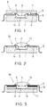
- Fig. 1 is a sectional view showing the construction of one embodiment of a semiconductor package according to the present invention, the view particularly illustrating a QFP (Quad Flat Package) to which Fe-Ni-base lead frames 5 are joined.
- a ceramic substrate 1 has a cavity 1a formed therein to house a semiconductor chip 2.
- a chip mount 3 to which the semiconductor chip 2 is joined and mounted.
- the lead frames 5 are joined by fixing glass 4 or the like to the same side as where the semiconductor chip 2 is mounted, i.e., to opposite projected upper surfaces of the ceramic substrate 1 at its outer end portions.
- the lead frames 5 are electrically connected to corresponding electrodes of the semiconductor chip 2 by bonding wires 6.
- a ceramic sealing member (cap or lid) 7 is joined through the lead frames 5 to the upper side of the ceramic substrate 1, to which the semiconductor chip 2 has been joined and mounted, by sealing glass 8, e.g., low melting point glass.
- the semiconductor chip 2 is hermetically sealed off by the sealing member 7.
- the ceramic substrate 1 and the ceramic sealing member 7 are each formed of the high thermal conductive silicon nitride sintered body of any of above Examples 1 to 16.
- a semiconductor package 9 of this Example 17 is thus constructed.
- the semiconductor package Since the ceramic substrate 1 and the ceramic sealing member 7 are each formed of the silicon nitride sintered body which is superior in both thermal conductivity and mechanical strength, the semiconductor package has a good characteristic of heat releasing and is sufficiently adaptable for an increase in output power and heat generation of the semiconductor chip 2. In addition, the semiconductor package is less susceptible to cracks due to the external force imposed when mounted or cracks due to the thermal stress caused by the difference in thermal expansion, and hence can ensure stable reliability of the operation for a long term.
- Example 17 is the case where both ceramic substrate 1 and the ceramic sealing member 7 are constituted by using the high thermal conductive silicon nitride sintered body of this invention.
- improvements for the semiconductor package can be effectively obtained, and such modifications or configurations are, of course, included within the scope of the present invention.
- FIG. 2 is a sectional view showing the construction of another embodiment of the semiconductor package according to the present invention.
- a semiconductor package 9a shown in Fig. 2 is of the same construction as in Example 17 except that sealing glass 10 is poured into the cavity 1a to thereby hermetically seal off the semiconductor chip 2, instead of using the ceramic sealing member 7 in the semiconductor package 9 of Fig. 1.
- the semiconductor package 9a is also improved in both heat releasing and durability as with Example 17.
- Fig. 3 is a sectional view showing the construction of still another embodiment of the semiconductor package according to the present invention.
- a flat ceramic substrate 1b is used, a rectangular frame-shaped metal ring 11 is fixed unitarily to an upper surface of the ceramic substrate 1b, and the lead frames 5 are joined unitarily to an upper surface of the metal ring 11 through a solder layer 12. Further, sealing glass 10 is poured into the cavity 1a formed at the center of the metal ring 11 to thereby hermetically seal off the semiconductor chip 2.
- the semiconductor package 9b of this Example 19 is further improved in heat releasing, because the ceramic substrate 1b is formed of the high thermal conductive silicon nitride sintered body and the metal ring 11 having the high thermal conductivity is employed.
- Examples 17 to 19 are illustrated as using QFPs (Quad Flat Packages) as the semiconductor packages, the present invention is not limited thereto, but is equally applicable to other semiconductor packages such as DIP (Dual In-line Package) type using lead frames, BGA (Ball Grid Array) type using solder balls, PGA (Pin Grid Array) type using lead pins, and LGA (Land Grid Array) type using input/output lands.
- DIP Direct In-line Package
- BGA Ball Grid Array
- PGA Pein Grid Array
- LGA Land Grid Array
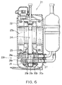
- Figs. 6 and 7 are a vertical and horizontal sectional view, respectively, showing the exemplified structure of an enclosed rotary compressor in which the high thermal conductive silicon nitride sintered body according to the present invention is used as a structural member, particularly, a sliding member.
- a motor 23a and a compressing element 23b are installed within a casing 22.
- the compressing element 23b is arranged such that a rotary shaft 24 extending from the motor 23a is inserted through a main bearing 25 and a sub-bearing 26 with two cylinders 28a, 28b disposed through a partition plate 27 between the main bearing 25 and the sub-bearing 26.
- cylindrical rollers 30a, 30b are fitted over eccentric portions 29a, 29b formed on the rotary shaft 24 and vanes 31a, 31b are disposed to be normally pressed into contact with the rollers 30a, 30b rotating in an eccentric manner, respectively, as shown in Fig. 7.
- the vanes 31a, 31b are reciprocally moved upon rotation of the eccentric portions 29a, 29b and the rollers 30a, 30b while keeping slide contact with outer peripheral surfaces of the corresponding rollers, to thereby partition the interiors of the cylinders 28a, 28b in terms of pressure.
- rollers 30a, 30b with the high thermal conductive silicon nitride sintered body of any of above Examples 1 to 16, conducting an endurance test in a similar manner, and measuring a wear of each roller 30a, 30b, the wear was reduced to about 1/15 of that in the prior art roller made of Monichro (Mo - Ni - Cr) cast iron.
- vanes 31a, 31b With the high thermal conductive silicon nitride sintered body of any of above Examples 1 to 16, and measuring a wear of each vane after an endurance test, it was confirmed that the wear was likewise reduced to about 1/15 of that in the prior art vane made of SKH-51.
- Fig. 8 is a sectional view showing the construction of a diesel engine in which the high thermal conductive silicon nitride sintered body according to the present invention is used as a high-temperature corrosion-resistant member and a sliding member.
- the high thermal conductive silicon nitride sintered bodies of above Examples 1 to 16 which are also superior in high-temperature strength, as component parts of a thermal engine, e.g., a diesel engine as shown in Fig. 8, the operating temperature can be set to a higher value than in the parts made of conventional metallic materials, and hence thermal efficiency can be improved remarkably.
- the silicon nitride sintered bodies of above Examples 1 to 16 can be practically applied to various structural parts.
- These structural parts include high-temperature corrosion-resistant members such as a cylinder head 40 which is repeatedly brought into contact with a valve 40 in a combustion gas atmosphere at high temperature, a body of the valve 40, as well as a hot plug 42 and a glow plug 43 for a preliminary combustion chamber.
- Other applicable structural members are a cylinder liner 44, a piston crown 45 and so on which are moved at a high speed while sliding mutually, are kept in contact with the combustion gas at high temperature, and hence require both high wear resistance and high corrosion resistance.
- the silicon nitride sintered bodies of above Examples can also be applied to parts around the engine cylinder, i.e., sliding members such as a rocker arm tip 46 and a top seat 47; a tappet 48 and a cam 49; etc. which are moved reciprocally to move the valve 40 back and forth while sliding mutually.
- sliding members such as a rocker arm tip 46 and a top seat 47; a tappet 48 and a cam 49; etc. which are moved reciprocally to move the valve 40 back and forth while sliding mutually.
- turbocharger rotating blade
- turbocharger supercharger
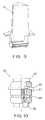
- Fig. 9 is a perspective view showing still another embodiment in which a moving blade (rotor) 55 for use with an aircraft or a gas turbine for power generation is formed of the silicon nitride sintered body of any of above Examples 1 to 16.
- the moving blade 55 of the gas turbine is brought into contact with combustion gas at high temperature during the operation, and is subject to extremely large tensile stress acting in the longitudinal direction of the moving blade due to centrifugal forces produced upon rotation.
- the moving blade 55 of the gas turbine with the silicon nitride sintered body of any of above Examples 1 to 16 which is superior in both strength and corrosion resistance at high temperature, durability of the moving blade can be improved remarkable in comparison with the conventional moving blade made of a super alloy.
- the blade weight becomes smaller than that of the metallic one, the magnitude of centrifugal forces to be generated can be reduced, and since any expensive super alloy material is not used, the blade can be manufactured at a lower cost. Additionally, the operating temperature can be increased in comparison with the case of using the metallic moving blade. This makes it possible to improve thermal efficiency in the operation of the gas turbine as a thermal engine, and hence to reduce fuel consumption.
- silicon nitride sintered body is applied to the moving blade 55 of the gas turbine in this Example, it is also applicable to other structural members such as stationary blades (stators), combustion tubes, heat exchangers and so on of gas turbines.
- Fig. 10 is a sectional view showing the structure of a high-frequency receiving tube 60 provided with a ceramic enclosure as a structural member which is formed of the high thermal conductive silicon nitride sintered body of Example 3 which has the thermal conductivity of 115 W/(m ⁇ K) and the three-point bending strength of 98 kg/mm 2 .
- the silicon nitride sintered body prepared with the similar process as in Example 3 is cut and ground into a ceramic enclosure 61 having a predetermined shape, and an anode 62, a grid 63, a cathode 64 and a heater 65 are built in the ceramic enclosure 61.
- the high-frequency receiving tube 60 has a good characteristic of heat releasing, is sufficiently adaptable for power-up of reception characteristics, and exhibits superior durability.
- silicon nitride structural member is applied to the ceramic enclosure of the high-frequency receiving tube 60 in this Example, its application is not limited to the receiving tube 60.
- the silicon nitride structural member can also be employed as a material for enclosures of electronic tubes such as X-ray tubes, magnetrons and arresters, or enclosures of various transmitting tubes, which particularly require a high degree of electric insulation, heat resistance and structural strength.
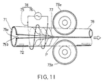
- Fig. 11 is a side view showing an embodiment in which the silicon nitride sintered body according to the present invention is applied to shaping rolls of a welded pipe manufacture machine.
- the welded pipe manufacture machine comprises a plurality of shaping rolls 73a, 73b... for pressing a strip steel 71 of desired dimensions in predetermined directions so as to form a cylindrical open pipe 72, and a high-frequency welder 74.
- the high-frequency welder 74 comprises a work coil 75 disposed just upstream of a welding point P of the open pipe 72 to surround the pipe's outer circumference, and a power supply 76 for supplying a high-frequency current to the work coil 75.
- the shaping rolls 73a, 73b are each formed by cutting and grinding the silicon nitride sintered body prepared with the similar process as in Example 3.
- the strip steel 71 fed as a raw material is pressed by a plurality of shaping rolls (not shown) so that it is gradually formed into the circular open pipe 72.
- a heating current is induced in the open pipe 72 to flow along current paths 77 shown in Fig. 11. Because the currents flow in abutting edges 79a, 79b of the open pipe 72, the edges jointly defining a V-shape, substantially parallel to each other in opposite directions, those currents are concentrated in the abutting edges 79a, 79b due to the so-called proximity effect of high-frequency currents.
- the abutting edges 79a, 79b are heated up to high temperature by the Joule's heat generated by the currents. Then, the open pipe 72 is pressed sideways by the shaping rolls (squeezing roll and guide roll) 73a, 73b disposed just downstream of the high-frequency welder 74, so that the abutting edges 79a, 79b of the open pipe 72 are welded together to form a welded pipe 78.
- the conventional shaping rolls made of the hard metal have accompanied various problems below. Roll bearings are damaged in a short period of time to cause abnormal vibration, resulting in failed products; or the shaping rolls are cracked, deformed and/or damaged due to impact forces acting upon them, thereby deteriorating surface properties of the product; or the shaping rolls are broken due to thermal shocks caused by cooling water sprayed to prevent the rolls from overly increasing in temperature.
- the shaping rolls 73a, 73b are each formed of the silicon nitride sintered body which is superior in high-temperature strength, thermal shock resistance, electric insulation and wear resistance, the stray current, etc. can be effectively prevented from leaking out of the high-frequency welder 74, and hence the bearings can be effectively prevented from being damaged due to electrolytic erosion induced by the leaked current. Also since the silicon nitride sintered body has smaller weight and higher wear resistance than the conventional materials, maintenance and handling of the rolls are facilitated, the rolls are less susceptible to damage and deformation, and quality of the welded pipe as a product can be improved remarkably.
- the silicon nitride sintered body according to the present invention is applied to the ceramic substrate of the semiconductor package, the sliding members of the compressor, the sliding members of the engine and the gas turbine, and the enclosure.
- the silicon nitride sintered body according to the present invention is not limited to the above members in its application, but is applicable to a variety of fields owing to superior characteristics of dielectric strength, wear resistance, thermal shock resistance, light weight, resistance to molten metal, and corrosion resistance, in addition to the high thermal conductivity along with the inherent high mechanical strength.
- the silicon nitride sintered body according to the present invention is less subject to wetting by various molten metals and is highly resistant to corrosion, it can be applied to cylinder members and plunger members of dicasting apparatus for Zn and so on.
- the silicon nitride sintered body is suitable as a melt-resistant material of crucibles and jig members for raising single crystals of metals and metal compounds.
- superior characteristics of dielectric strength, weather resistance and toughness it is also applicable to insulators for holding high-voltage lines.
- by utilizing superior characteristics of mechanical strength, rigidity, wear resistance and burning resistance it can be used as a material for forming balls and inner and outer races of various bearings.
- the silicon nitride sintered body can also be used as a structural member of a nozzle for ejecting highly hard particles therethrough in a blasting apparatus.
- the high thermal conductive silicon nitride sintered body according to the present invention may be manufactured by adding the predetermined amount of a rare earth element to fine silicon nitride powder having predetermined values of purity and grain size, pressing and sintering the mixture, and setting a cooling rate of the sintered body immediately after the sintering process to be slow not higher than 100°C per hour, the grain boundary phase in the sintered body structure is changed from the amorphous state into the state containing a crystal phase as opposed to the case of quickly cooling the sintered body by turning off power supply to the furnace as with the prior art, whereby the compact sintered body having the high mechanical strength and the high thermal conductivity can be obtained.
- the high thermal conductive silicon nitride sintered body of the present invention to structural members such as various sliding members, high-temperature corrosion-resistant members of gas turbines and automobile engines, ceramic enclosures of electronic tubes and receiving/transmitting tubes, and shaping rolls, as well as semiconductor packages, heaters, etc., durability, heat releasing and service life of the applied products can be improved remarkably, making the products adaptable for demand to increase output power and prolong service life.
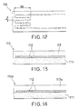
- Figs. 12 and 13 are a plan and sectional view, respectively, showing the construction of one embodiment of a heater according to the present invention.
- a ceramic substrate 111 is formed of the high thermal conductive silicon nitride sintered body which is prepared as with Example 3 and has the thermal conductivity of 115 W/(m ⁇ K) and the three-point bending strength of 98 kg/mm 2
- a heating resistor 112 made of tantalum nitride (Ta 2 N) is formed over the surface of the ceramic substrate 111
- an insulating layer 113 is formed unitarily onto the surface of the ceramic substrate 111 so as to cover the heating resistor 112.
- the ceramic substrate 111 made of the above high thermal conductive silicon nitride sintered body has dimensions of 20 x 10 x 1.0 mm, and the heating resistor 112 is formed in a zigzag pattern with a width W of 3 mm and a pitch L of 0.2 mm.
- the insulating layer 113 and the ceramic substrate 111 are each formed of the high thermal conductive silicon nitride sintered body prepared as with Example 3.
- the heater of this Example 25 since the ceramic substrate 111 and the insulating layer 113 jointly supporting the heating resistor 112 are each formed of the silicon nitride sintered body having the high mechanical strength and the high thermal conductivity, the heater can simultaneously exhibit both superior thermal response for ON-OFF operation of the voltage applied to the heating resistor 112 and superior durability.
- the ceramic substrate 111 and the insulating layer 113 are made of the same material, it is possible to effectively prevent the occurrence of peeling-off or cracks due to the difference in thermal expansion between the two members, and hence to further improve durability.
- Fig. 14 is a sectional view showing another embodiment of the heater according to the present invention.
- a heater 110a of this Example 26 shown in Fig. 14 is the same as the heater 110 of Example 25 except that an insulating layer 113a is formed of an insulating material such as a conventional Si 3 N 4 sintered body, Al 2 O 3 or mullite, instead of the insulating layer 113 formed of the high thermal conductive silicon nitride sintered body shown in Fig. 13.
- an insulating layer 113a is formed of an insulating material such as a conventional Si 3 N 4 sintered body, Al 2 O 3 or mullite, instead of the insulating layer 113 formed of the high thermal conductive silicon nitride sintered body shown in Fig. 13.
- the heater 110a of this Example 26 has the high thermal conductivity in the direction downward in Fig. 14 and exhibits high thermal response likewise.
- Fig. 15 is a sectional view showing still another embodiment of the heater according to the present invention. Specifically, a heater 110b of this Example 27 shown in Fig. 15 is the same as the heaters 110a, 110b of Examples 25 and 26 except that the insulating layers are eliminated from the heaters 110a, 110b shown in Figs. 13 and 14.
- the heater 110b of this Example 27 has a simpler structure that no insulating layer is coated and the heating resistor 112 is exposed to the surface. Accordingly, the heater 110b of this Example 27 having the simpler structure can be sufficiently employed in the case where other conductors and so on which may short-circuit upon contact with the heating resistor 112 are not present around the heater 110b.
- Fig. 16 is a sectional view showing still another embodiment of the heater according to the present invention.
- a heater 110c of this Example 28 shown in Fig. 16 is the same as the heater 110 of Example 25 except that a ceramic substrate 111a is formed of an insulating material such as a conventional Si 3 N 4 sintered body, Al 2 O 3 or mullite, instead of the ceramic substrate 111 formed of the high thermal conductive silicon nitride sintered body shown in Fig. 13.
- a ceramic substrate 111a is formed of an insulating material such as a conventional Si 3 N 4 sintered body, Al 2 O 3 or mullite, instead of the ceramic substrate 111 formed of the high thermal conductive silicon nitride sintered body shown in Fig. 13.
- the heater 110c of this Example 28 has the high thermal conductivity in the direction upward in Fig. 16 and exhibits high thermal response likewise.
- an Al 2 O 3 heater of this Comparative Example 8 was fabricated through the same process as in Example 25 except that a ceramic substrate and an insulating layer were each formed of an Al 2 O 3 sintered body which had the thermal conductivity of 25 W/(m ⁇ K) and the three-point bending strength of 31 kg/mm 2 , instead of the ceramic substrate 111 and the insulating layer 113 used in the heater 110 of Example 25 shown in Fig. 13.
- an AlN heater of this Comparative Example 9 was fabricated through the same process as in Example 25 except that a ceramic substrate and an insulating layer were each formed of an AlN sintered body which had the thermal conductivity of 140 W/(m ⁇ K) and the three-point bending strength of 32 kg/mm 2 , instead of the ceramic substrate 111 and the insulating layer 113 used in the heater 110 of Example 25 shown in Fig. 13.
- the results shown in Fig. 17 were obtained by setting the amount of power supplied to the heating resistor 112 of each heater to 15 W and measuring time-dependent changes in the surface temperature of the heater to evaluate heating-up characteristics (thermal response) of the heaters. Also, the results shown in Table 4 below were obtained by measuring the heating-up rate and the power density as indices for heating abilities of the heaters.
- the heater of Example 25 in which the ceramic substrate and the insulating layer were formed of the silicon nitride sintered body having the high mechanical strength and the high thermal conductivity, provided a quicker rise in the surface temperature immediately after the start of power supply and better thermal response than the heater of Comparative Example 8 in which they were formed of the Al 2 O 3 sintered body.
- the heater of Example 25 and the heater of Comparative Example 9 being formed of the AlN sintered body exhibit comparable heating-up characteristics because both have the high thermal conductivity.
- the heater of Comparative Example 9 has the three-point bending strength about 1/3 time that of the heater of Example 25, and hence the former's durability is extremely inferior to the latter's.
- the heaters are not limited to the flat form, but may be manufactured into any desired shape such as a tubular or annular shape depending on, e.g., the configuration of the object to be heated.
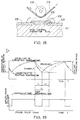
- Fig. 18 is a sectional view showing one embodiment of a thick-film type thermal head according to the present invention. Note that the same components as those in the prior art shown in Fig. 21 are denoted by the same reference numerals and the description of those components will not repeated here.
- a heating resistor 102 and a wear-resistant layer 105 are laminated on the surface of a high thermal conductive silicon nitride sintered body 107 which is prepared as with Example 3 and has the surface roughness Ra not greater than 1 ⁇ m, the thermal conductivity of 115 W/(m ⁇ K) and the three-point bending strength of 98 kg/mm 2 .
- Electric leads (electrodes) 103 are formed to be joined to both end portions of the heating resistor 102 by transferring and baking a conductor paste such as Ag, Pd - Ag or Pt - Au.
- a main feature of the thermal head of this Example is that its ceramic substrate is formed of the high thermal conductive silicon nitride sintered body 107 which has the thermal conductivity 4 to 5 times that of the conventional alumina substrate.
- the surface roughness Ra (mean roughness along the center line specified in JIS 0601) greatly affects the adhesion and the chemical bonding strength between the sintered body 107 and the heating resistor 102 disposed thereon. Therefore, the surface roughness Ra is preferably set to be not greater than 1 ⁇ m. If the surface roughness Ra exceeds 1 ⁇ m, the adhesion and the bonding strength of the sintered body 107 with respect to the heating resistor 102 and the electric leads 103 would be reduced, resulting in deterioration of reliability and durability of the thermal head.
- the high thermal conductive silicon nitride sintered body 107 with the surface roughness Ra being not greater than 1 ⁇ m can be prepared by, e.g., grinding the surface of the sintered body into a mirror surface in a usual manner.
- the heating resistor 102 generates heat upon application of a pulse voltage between the electric leads (electrodes) 103 and 103, causing a color former in heat-sensitive recording paper to develop a color in the form of dots.
- the heating resistor is formed by preparing a material, e.g., Ta 2 N, NiCr alloy, Nesa film, Ta - SiO 2 or Ta - Si, into a paste and then coating the paste by the film forming technique such as screen printing.
- the wear resistant layer 105 serves to protect the heating resistor 102 against wear caused by contact with the heat-sensitive recording paper, and is formed of materials such as SiO 2 - Ta 2 O 3 , SiC, Al 2 O 3 and SiO 2 .
- the heating resistor 102 of the thermal head When a pulse voltage is applied to the heating resistor 102 through the electrodes 103, 103, the heating resistor 102 of the thermal head generates heat, whereupon the color former coated on heat-sensitive recording paper 104, which is pressed by a feed roller 106 against the heating resistor 102 through the wear-resistant layer 105, develops a color in the form of dots.
- the time during which the pulse voltage is applied is usually on the order of 1 to 10 ms (milli-second).
- the heat generated by the heating resistor 102 is released to the outside through the high thermal conductive silicon nitride sintered body 107, and the heating resistor 102 is cooled down to a predetermined lower limit of the printing temperature. Then, upon application of the next pulse voltage, the heating and cooling cycles are similarly repeated so that a number of dots develop a color on the moving heat-sensitive recording paper to thereby record an image of letters, symbols or figures depending on an array of the color-developed dots.
- Fig. 19 is a graph showing time-dependent changes in heating resistor temperature resulted from a printing test in which the thick-film type thermal head of Example 29 using the high thermal conductive silicon nitride sintered body 107 shown in Fig. 18 and the conventional thick-film type thermal head using the Al 2 O 3 ceramic substrate shown in Fig. 21 were each actually fitted to a printer.
- the thermal head of this Example employs the high thermal conductive silicon nitride sintered body 107 as a ceramic substrate, it has a superior characteristic of heat releasing after disappearance of the pulse voltage, and hence the heat releasing time t 1 required for the heating resistor to cool down to the predetermined lower limit of the printing temperature is much shorter than the heat releasing time t 0 required for the prior art using the ceramic substrate 101 made of Al 2 O 3 .
- a heating resistor disposed between a pair of electric leads has been formed into a band-like shape such that it has a uniform section at any axial position.
- a heating resistor 102a of the thermal head can also be formed such that its end portions connected to the electrodes 103, 103 are formed into a band-like shape as conventionally, whereas the width W of its central portion is set to be smaller than that of the end portions, thus providing a centrally narrowed configuration as a whole.
- the central portion of the heating resistor 102a has a maximum resistance value.
- the region where the temperature reaches the ink dissolving point is gradually enlarged.
- the heater and the thermal head of the present invention since ceramic substrates, which determine their characteristics of mechanical strength and thermal response, are each formed of the novel high thermal conductive silicon nitride sintered body which has the thermal conductivity not less than 60 W/(m ⁇ K), in addition to the high mechanical strength inherently given to a sintered body of silicon nitride, the heater and the thermal head can provide not only superior thermal response for ON-OFF operation of the voltage applied to the heating resistor, but also superior durability.
- the thermal head since the high thermal conductive silicon nitride sintered body is employed which has the thermal conductivity at least 2 to 5 times that of alumina conventionally used, the falling time required for the heating resistor, once heated up to the printing temperature, to cool down to predetermined temperature is reduced remarkably. Therefore, the repetition period of printing given by the sum of the rising time and the falling time of the heating resistor temperature is shortened to a large extent. As a result, the thermal response of the thermal head can be greatly improved and the recording speed can be greatly increased.
Landscapes
- Engineering & Computer Science (AREA)
- Chemical & Material Sciences (AREA)
- Ceramic Engineering (AREA)
- General Engineering & Computer Science (AREA)
- Manufacturing & Machinery (AREA)
- Materials Engineering (AREA)
- Structural Engineering (AREA)
- Organic Chemistry (AREA)
- Mechanical Engineering (AREA)
- Ceramic Products (AREA)
Claims (8)
- Gleitteil, das aus einem hochgradig wärmeleitenden Siliziumnitrid-Strukturteil ausgebildet ist, das aus Siliziumnitridpartikeln und einer Korngrenzenphase, wobei eine Kristallverbindungsphase in der Korngrenzenphase nicht weniger als 20 Vol. % bezüglich der gesamten Korngrenzenphase beträgt, besteht und die Wärmeleitfähigkeit von nicht weniger als 60 W/(m · K) aufweist.
- Eine Hülle, die aus einem hochgradig wärmeleitenden Siliziumnitrid-Strukturteil ausgebildet ist, das aus Siliziumnitridpartikeln und einer Korngrenzenphase, wobei eine Kristallverbindungsphase in der Korngrenzenphase nicht weniger als 20 Vol. % bezüglich der gesamten Korngrenzenphase beträgt, besteht und die Wärmeleitfähigkeit von nicht weniger als 60 W/(m · K) aufweist.
- Eine Halbleiterverpackung, die ein Keramiksubstrat, auf dem ein Halbleiterchip montiert ist, Zuleitungsrahmen, die mit derselben Oberfläche des Keramiksubstrates, auf der der Halbleiterchip montiert ist, verbunden sind, und Bonddrähte zum elektrischen Verbinden des Halbleiterchips und der Zuleitungsrahmen aufweist, bei dem das Keramiksubstrat aus einem hochgradig wärmeleitenden Silitiumnitrid-Strukturteil ausgebildet ist, das aus Siliziumnitridpartikeln und einer Korngrenzenphase, wobei eine Kristallverbindungsphase in der Korngrenzenphase nicht weniger als 20 Vol. % bezüglich der gesamten Korngrenzenphase beträgt, besteht und die Wärmeleitfähigkeit von nicht weniger als 60 W/(m · K) aufweist.
- Ein Heizelement, bei dem ein Heizwiderstand in einer Einheitsstruktur mit einem hochgradig wärmeleitenden Silitiumnitrid-Strukturteil angeordnet ist, das aus Siliziumnitridpartikeln und einer Korngrenzenphase, wobei eine Kristallverbindungsphase in der Korngrenzenphase nicht weniger als 20 Vol. % bezüglich der gesamten Korngrenzenphase beträgt, besteht und die Wärmeleitfähigkeit von nicht weniger als 60 W/(m · K) aufweist.
- Ein Heizelement, das ein Keramiksubstrat, einen Heizwiderstand, der auf dem Keramiksubstrat angeordnet ist, und eine Isolierschicht, die auf das Keramiksubstrat zum Bedecken des Heizwiderstandes beschichtet ist, aufweist, bei dem die Isolierschicht aus einem hochgradig wärmeleitenden Siliziumnitrid-Strukturteil ausgebildet ist, das aus Siliziumnitridpartikeln und einer Korngrenzenphase, wobei eine Kristallverbindungsphase in der Korngrenzenphase nicht weniger als 20 Vol. % bezüglich der gesamten Korngrenzenphase beträgt, besteht und die Wärmeleitfähigkeit von nicht weniger als 60 W/(m · K) aufweist.
- Ein Thermokopf, bei dem ein Heizwiderstard und eine abnutzungswiderstandsfähige Schicht in einer Einheitsstruktur auf der Oberfläche eines hochgradig wärmeleitenden Siliziumnitrid-Strukturteils laminiert sind, das aus Siliziumnitridpartikeln und einer Korngrenzenphase, wobei eine Kristallverbindungsphase in der Korngrenzenphase nicht weniger als 20 Vol. % bezüglich der gesamten Korngrenzenphase beträgt, besteht und die Wärmeleitfähigkeit von nicht weniger als 60 W/(m · K) aufweist.
- Thermokopf nach Anspruch 6, bei dem
der Heizwiderstand aus mindestens einem Element oder einer Verbindung gemacht ist, das/die ausgewählt ist aus der Gruppe, die besteht aus Ti, Zr, Hf, V, Cr, Mo, W, NiCr, Nesa-Film, Ta-Si, Ta2N, Ta-SiO2 und Nb-SiO2. - Thermokopf nach Anspruch 6, bei dem
der Heizwiderstand an beiden Enden mit entsprechenden Elektroden verbunden ist, wobei die Endabschnitte des Heizwiderstandes, die mit den Elektroden verbunden sind jeweils in einer Streifenform ausgebildet sind und die Breite eines Zentralabschnittes des Heizwiderstandes so eingestellt ist, daß sie kleiner als die Breite der beiden Endabschnitte ist.
Applications Claiming Priority (6)
| Application Number | Priority Date | Filing Date | Title |
|---|---|---|---|
| JP333595/93 | 1993-12-27 | ||
| JP33359593A JP3445342B2 (ja) | 1993-12-27 | 1993-12-27 | 高熱伝導性窒化けい素構造部材および半導体パッケージ |
| JP333596/93 | 1993-12-27 | ||
| JP33359693 | 1993-12-27 | ||
| JP05333596A JP3089926B2 (ja) | 1993-12-27 | 1993-12-27 | ヒーターおよびサーマルヘッド |
| JP33359593 | 1993-12-27 |
Publications (3)
| Publication Number | Publication Date |
|---|---|
| EP0660397A2 EP0660397A2 (de) | 1995-06-28 |
| EP0660397A3 EP0660397A3 (de) | 1996-03-27 |
| EP0660397B1 true EP0660397B1 (de) | 2000-03-15 |
Family
ID=26574564
Family Applications (1)
| Application Number | Title | Priority Date | Filing Date |
|---|---|---|---|
| EP94120716A Expired - Lifetime EP0660397B1 (de) | 1993-12-27 | 1994-12-27 | Siliziumnitridteil mit hoher Wärmeleitfähigkeit, Halbleitergehäuse, Heizung und thermischer Kopf |
Country Status (4)
| Country | Link |
|---|---|
| US (1) | US5698896A (de) |
| EP (1) | EP0660397B1 (de) |
| KR (1) | KR0143870B1 (de) |
| DE (1) | DE69423447T2 (de) |
Cited By (1)
| Publication number | Priority date | Publication date | Assignee | Title |
|---|---|---|---|---|
| WO2024197211A1 (en) * | 2023-03-22 | 2024-09-26 | Materion Corporation | Integral resistance heaters including niobium and processes for making same |
Families Citing this family (24)
| Publication number | Priority date | Publication date | Assignee | Title |
|---|---|---|---|---|
| JP2853599B2 (ja) * | 1995-03-10 | 1999-02-03 | 日本電気株式会社 | 半導体装置の製造方法 |
| US6046499A (en) * | 1996-03-27 | 2000-04-04 | Kabushiki Kaisha Toshiba | Heat transfer configuration for a semiconductor device |
| US6232657B1 (en) * | 1996-08-20 | 2001-05-15 | Kabushiki Kaisha Toshiba | Silicon nitride circuit board and semiconductor module |
| US5909058A (en) * | 1996-09-25 | 1999-06-01 | Kabushiki Kaisha Toshiba | Semiconductor package and semiconductor mounting part |
| JPH11335158A (ja) | 1998-03-24 | 1999-12-07 | Sumitomo Electric Ind Ltd | セラミックス基板及びその研磨方法 |
| JP4346151B2 (ja) * | 1998-05-12 | 2009-10-21 | 株式会社東芝 | 高熱伝導性窒化けい素焼結体およびそれを用いた回路基板並びに集積回路 |
| BR9900253A (pt) | 1999-02-02 | 2000-08-29 | Companhia Brasileira Carbureto | Recipiente de alumìnio e aço inoxidável a formação de eletrodos de autocozimento para a utilização em baixos-fornos elétricos de redução |
| BR9900252A (pt) | 1999-02-02 | 2000-08-29 | Companhia Brasileira Carbureto | Recipiente de aço inoxidável para a formação de eletrodos de autocozimento para a utilização em baixos-fornos elétricos de redução |
| US6391812B1 (en) * | 1999-06-23 | 2002-05-21 | Ngk Insulators, Ltd. | Silicon nitride sintered body and method of producing the same |
| DE10010461A1 (de) * | 2000-03-03 | 2001-09-13 | Infineon Technologies Ag | Vorrichtung zum Verpacken elektronischer Bauteile mittels Spritzgußtechnik |
| EP1201623B1 (de) * | 2000-10-27 | 2016-08-31 | Kabushiki Kaisha Toshiba | Keramiksubstrat aus Siliziumnitrid und das Substrat verwendende keramische Schaltkreisplatte |
| CN1856454A (zh) * | 2003-09-25 | 2006-11-01 | 株式会社东芝 | 氮化硅耐磨部件及其制造方法 |
| KR100510556B1 (ko) * | 2003-11-11 | 2005-08-26 | 삼성전자주식회사 | 초박형 반도체 패키지 및 그 제조방법 |
| DE102004003119A1 (de) * | 2004-01-21 | 2005-08-11 | BSH Bosch und Siemens Hausgeräte GmbH | Vorrichtung zum Erwärmen von Speisen mittels induktiver Kopplung und Vorrichtung zur Übertragung von Energie |
| US7019390B2 (en) * | 2004-02-03 | 2006-03-28 | Visteon Global Technologies, Inc. | Silicon nitride insulating substrate for power semiconductor module |
| WO2008032427A1 (en) | 2006-09-13 | 2008-03-20 | Kabushiki Kaisha Toshiba | Slide member and bearing utilizing the same |
| TWM328763U (en) * | 2007-05-21 | 2008-03-11 | Univ Nat Taiwan | Structure of heat dissipation substrate |
| US8304660B2 (en) * | 2008-02-07 | 2012-11-06 | National Taiwan University | Fully reflective and highly thermoconductive electronic module and method of manufacturing the same |
| RU2495060C1 (ru) * | 2012-07-04 | 2013-10-10 | Федеральное государственное унитарное предприятие Особое конструкторско-технологическое бюро "ОРИОН" | Антифрикционный композиционный материал |
| CN105129720A (zh) * | 2015-07-25 | 2015-12-09 | 中国科学院地质与地球物理研究所 | Mems传感器的封装结构及封装方法 |
| US10062636B2 (en) * | 2016-06-27 | 2018-08-28 | Newport Fab, Llc | Integration of thermally conductive but electrically isolating layers with semiconductor devices |
| CN111108818B (zh) | 2017-09-21 | 2022-06-28 | 京瓷Avx元器件公司 | 具有低热阻的电绝缘热连接器 |
| CN116964021A (zh) * | 2021-03-30 | 2023-10-27 | 株式会社东芝 | 氮化硅烧结体、耐磨性构件及氮化硅烧结体的制造方法 |
| CN117069050A (zh) * | 2023-08-21 | 2023-11-17 | 无锡中微晶园电子有限公司 | 一种高热稳定mems压力传感器及其制备方法 |
Family Cites Families (12)
| Publication number | Priority date | Publication date | Assignee | Title |
|---|---|---|---|---|
| US3874915A (en) * | 1967-02-03 | 1975-04-01 | Hitachi Ltd | Silicon nitride on silicon oxide coatings for semiconductor devices |
| JPS60208626A (ja) * | 1984-03-30 | 1985-10-21 | Koyo Seiko Co Ltd | 腐食環境下で使用する回転部材支持装置 |
| JPS6135973A (ja) * | 1984-07-30 | 1986-02-20 | Hitachi Ltd | 感熱ヘツド |
| JPS62151359A (ja) * | 1985-12-25 | 1987-07-06 | Alps Electric Co Ltd | サ−マルヘツド |
| JPS62256768A (ja) * | 1986-04-30 | 1987-11-09 | 株式会社日立製作所 | 窒化けい素焼結体 |
| US4849605A (en) * | 1988-03-11 | 1989-07-18 | Oki Electric Industry Co., Ltd. | Heating resistor and method for making same |
| JPH089506B2 (ja) * | 1990-01-23 | 1996-01-31 | 日本碍子株式会社 | 窒化珪素体 |
| US5294750A (en) * | 1990-09-18 | 1994-03-15 | Ngk Insulators, Ltd. | Ceramic packages and ceramic wiring board |
| JP2876776B2 (ja) * | 1990-11-07 | 1999-03-31 | 住友電気工業株式会社 | 窒化ケイ素焼結体 |
| JP3044630B2 (ja) * | 1991-02-06 | 2000-05-22 | ボッシュ ブレーキ システム株式会社 | セラミックヒータ型グロープラグ |
| JP2804393B2 (ja) * | 1991-07-31 | 1998-09-24 | 京セラ株式会社 | セラミックヒータ |
| DE69316118T2 (de) * | 1992-09-08 | 1998-04-23 | Toshiba Kawasaki Kk | Siliciumnitrid-Sinterkörper mit hoher Wärmeleitfähigkeit und Verfahren zu seiner Herstellung |
-
1994
- 1994-12-26 KR KR1019940038360A patent/KR0143870B1/ko not_active Expired - Lifetime
- 1994-12-27 EP EP94120716A patent/EP0660397B1/de not_active Expired - Lifetime
- 1994-12-27 DE DE69423447T patent/DE69423447T2/de not_active Expired - Fee Related
- 1994-12-27 US US08/364,195 patent/US5698896A/en not_active Expired - Lifetime
Cited By (1)
| Publication number | Priority date | Publication date | Assignee | Title |
|---|---|---|---|---|
| WO2024197211A1 (en) * | 2023-03-22 | 2024-09-26 | Materion Corporation | Integral resistance heaters including niobium and processes for making same |
Also Published As
| Publication number | Publication date |
|---|---|
| KR950021438A (ko) | 1995-07-26 |
| EP0660397A3 (de) | 1996-03-27 |
| DE69423447T2 (de) | 2000-12-07 |
| KR0143870B1 (ko) | 1998-07-01 |
| US5698896A (en) | 1997-12-16 |
| DE69423447D1 (de) | 2000-04-20 |
| EP0660397A2 (de) | 1995-06-28 |
Similar Documents
| Publication | Publication Date | Title |
|---|---|---|
| EP0660397B1 (de) | Siliziumnitridteil mit hoher Wärmeleitfähigkeit, Halbleitergehäuse, Heizung und thermischer Kopf | |
| US6040039A (en) | Silicon nitride circuit board | |
| US6613443B2 (en) | Silicon nitride ceramic substrate, silicon nitride ceramic circuit board using the substrate, and method of manufacturing the substrate | |
| EP0587382B1 (de) | Leiterplatte aus Aluminiumnitrid und Verfahren zu ihrer Herstellung | |
| EP0778249B1 (de) | Gesintertes siliciumnitrid hoher wärmeleitfähigkeit und druckgeschweisste struktur | |
| JP3445342B2 (ja) | 高熱伝導性窒化けい素構造部材および半導体パッケージ | |
| JP3408298B2 (ja) | 高熱伝導性窒化けい素メタライズ基板,その製造方法および窒化けい素モジュール | |
| JPH0969672A (ja) | 窒化けい素回路基板 | |
| JP3193305B2 (ja) | 複合回路基板 | |
| JPH11135234A (ja) | 窒化アルミニウムヒーター | |
| JP2772273B2 (ja) | 窒化けい素回路基板 | |
| US6316116B1 (en) | Ceramic circuit board and method of manufacturing the same | |
| JP3946298B2 (ja) | セラミックス−金属傾斜機能材およびその製造方法 | |
| EP1811820B1 (de) | Prozess zur herstellung eines metallisierten aluminiumnitridsubstrats und dadurch erhaltenes substrat | |
| JP3204640B2 (ja) | ヒーターおよびサーマルヘッド | |
| JP3618422B2 (ja) | 高強度回路基板およびその製造方法 | |
| JP3226898B2 (ja) | 圧接構造を有するサイリスタ用窒化けい素放熱板およびそれを用いたサイリスタ | |
| JPH11292632A (ja) | 高熱伝導性窒化けい素構造部材の製造方法および半導体パッケ―ジの製造方法 | |
| JP3089926B2 (ja) | ヒーターおよびサーマルヘッド | |
| JP2999909B2 (ja) | サーマルヘッド及びその製造方法並びにこれを用いたサーマルプリンタ | |
| JPH11310466A (ja) | 高熱伝導性窒化けい素構造部材および半導体パッケージ | |
| JP4332824B2 (ja) | 高熱伝導窒化ケイ素質焼結体の製造方法およびその焼結体、基板、半導体素子用回路基板 | |
| JPH11100276A (ja) | 電子部品搭載用窒化ケイ素質基板及びその製造方法 | |
| JPH0964235A (ja) | 窒化けい素回路基板 | |
| JP2003327474A (ja) | 高熱伝導性窒化けい素構造部材および半導体パッケージ |
Legal Events
| Date | Code | Title | Description |
|---|---|---|---|
| PUAI | Public reference made under article 153(3) epc to a published international application that has entered the european phase |
Free format text: ORIGINAL CODE: 0009012 |
|
| 17P | Request for examination filed |
Effective date: 19941227 |
|
| AK | Designated contracting states |
Kind code of ref document: A2 Designated state(s): DE FR GB |
|
| PUAL | Search report despatched |
Free format text: ORIGINAL CODE: 0009013 |
|
| AK | Designated contracting states |
Kind code of ref document: A3 Designated state(s): DE FR GB |
|
| 17Q | First examination report despatched |
Effective date: 19960604 |
|
| GRAG | Despatch of communication of intention to grant |
Free format text: ORIGINAL CODE: EPIDOS AGRA |
|
| GRAG | Despatch of communication of intention to grant |
Free format text: ORIGINAL CODE: EPIDOS AGRA |
|
| GRAH | Despatch of communication of intention to grant a patent |
Free format text: ORIGINAL CODE: EPIDOS IGRA |
|
| GRAH | Despatch of communication of intention to grant a patent |
Free format text: ORIGINAL CODE: EPIDOS IGRA |
|
| GRAA | (expected) grant |
Free format text: ORIGINAL CODE: 0009210 |
|
| AK | Designated contracting states |
Kind code of ref document: B1 Designated state(s): DE FR GB |
|
| REF | Corresponds to: |
Ref document number: 69423447 Country of ref document: DE Date of ref document: 20000420 |
|
| ET | Fr: translation filed | ||
| PLBE | No opposition filed within time limit |
Free format text: ORIGINAL CODE: 0009261 |
|
| STAA | Information on the status of an ep patent application or granted ep patent |
Free format text: STATUS: NO OPPOSITION FILED WITHIN TIME LIMIT |
|
| 26N | No opposition filed | ||
| REG | Reference to a national code |
Ref country code: GB Ref legal event code: IF02 |
|
| PGFP | Annual fee paid to national office [announced via postgrant information from national office to epo] |
Ref country code: FR Payment date: 20021210 Year of fee payment: 9 |
|
| PGFP | Annual fee paid to national office [announced via postgrant information from national office to epo] |
Ref country code: GB Payment date: 20021224 Year of fee payment: 9 |
|
| PGFP | Annual fee paid to national office [announced via postgrant information from national office to epo] |
Ref country code: DE Payment date: 20030109 Year of fee payment: 9 |
|
| PG25 | Lapsed in a contracting state [announced via postgrant information from national office to epo] |
Ref country code: GB Free format text: LAPSE BECAUSE OF NON-PAYMENT OF DUE FEES Effective date: 20031227 |
|
| PG25 | Lapsed in a contracting state [announced via postgrant information from national office to epo] |
Ref country code: DE Free format text: LAPSE BECAUSE OF NON-PAYMENT OF DUE FEES Effective date: 20040701 |
|
| GBPC | Gb: european patent ceased through non-payment of renewal fee |
Effective date: 20031227 |
|
| PG25 | Lapsed in a contracting state [announced via postgrant information from national office to epo] |
Ref country code: FR Free format text: LAPSE BECAUSE OF NON-PAYMENT OF DUE FEES Effective date: 20040831 |
|
| REG | Reference to a national code |
Ref country code: FR Ref legal event code: ST |