EP0657702B1 - Dispositif pour la génération de deux rideaux d'air à sens de circulation opposée - Google Patents
Dispositif pour la génération de deux rideaux d'air à sens de circulation opposée Download PDFInfo
- Publication number
- EP0657702B1 EP0657702B1 EP94119293A EP94119293A EP0657702B1 EP 0657702 B1 EP0657702 B1 EP 0657702B1 EP 94119293 A EP94119293 A EP 94119293A EP 94119293 A EP94119293 A EP 94119293A EP 0657702 B1 EP0657702 B1 EP 0657702B1
- Authority
- EP
- European Patent Office
- Prior art keywords
- air
- arrangement
- fan
- air inlet
- door
- Prior art date
- Legal status (The legal status is an assumption and is not a legal conclusion. Google has not performed a legal analysis and makes no representation as to the accuracy of the status listed.)
- Expired - Lifetime
Links
Images

Classifications
-
- F—MECHANICAL ENGINEERING; LIGHTING; HEATING; WEAPONS; BLASTING
- F24—HEATING; RANGES; VENTILATING
- F24F—AIR-CONDITIONING; AIR-HUMIDIFICATION; VENTILATION; USE OF AIR CURRENTS FOR SCREENING
- F24F9/00—Use of air currents for screening, e.g. air curtains
-
- F—MECHANICAL ENGINEERING; LIGHTING; HEATING; WEAPONS; BLASTING
- F24—HEATING; RANGES; VENTILATING
- F24F—AIR-CONDITIONING; AIR-HUMIDIFICATION; VENTILATION; USE OF AIR CURRENTS FOR SCREENING
- F24F9/00—Use of air currents for screening, e.g. air curtains
- F24F2009/007—Use of air currents for screening, e.g. air curtains using more than one jet or band in the air curtain
Definitions
- Air curtains are used when on open doors or gates to prevent outside air from entering the room or an escape of room air to the outside should be prevented.
- An order to such Generating gate air curtains is known from DE-PS 30 50 685 known.
- the Ejector nozzle is used to create an induction air jet generate the with another fan from the air outlet blown air over the entire gate height to be able to transport. This so-called primary air is expelled from the air outlet at a lower pressure and wouldn't go far without the induction air jet enough to reach the ground.
- the known device is used in such a way that its air inlet faces the interior of the room, while the air outlet with the ejector nozzles from above is directed downwards parallel to the door opening. Thereby creates an air roller during operation, whose air flow near the floor from the door opening to the Interior is directed, as is also the case in the essay “Energy saving through the use of air curtain systems” in the magazine “Ki air conditioning cooling heating”, 9/1983 is described.
- the known device works satisfactorily as long as than the pressure inside the room the pressure of the Atmosphere outside the room corresponds. However, as soon as in the room more ventilation facilities effective or there is thermal buoyancy a negative pressure and the air curtain is no longer in able to penetrate outside air through the air curtain to prevent through. Rather, it flows near the bed due to the air flow directed there accordingly the air roller of the air curtain outside air one that creates a cold air lake next to the door.
- This type of airflow also creates a Air roller reaching far into the space to be protected.
- the outside air that is constantly sucked in increases compared to the previously explained variant Energy expenditure for tempering the air curtain.
- the Energy consumption is about twice as large as the first Variant if the same interior temperature and one Temperature difference between inside and outside of approx. 10 up to 20 K is assumed.
- Another embodiment known from practice provides for the use of two air curtains, to improve the shielding effect, the one on the inside of the door and the other on the Outside of the door is attached so that both Gate air curtain air rollers with opposite Generate sense of rotation, the descending air flow occurs between the rollers.
- the energy requirement is about the same like like a simple air roller, which is on the ground is directed outside.
- the blower equipment are arranged so that the rising air flow occurs between the rollers.
- This arrangement works the door air curtain directly adjacent to the door like a single gate air curtain according to the state of the art, i.e. the at high speed expelled air flows directly at the door opening down and gets on the ground towards that Inside the room and shortly thereafter redirected upwards.
- This The arrangement is for pressure equalization between the interior of the room and the outside atmosphere already extraordinary effective.
- the internal air roller flows in the opposite direction, though because of the reverse running air roller the door from the inner air roller no air to the outside can penetrate.
- the outer blower device As a result of the operational independence of the two Blower devices need the outer blower device not to be heated without doing so a deterioration in comfort in the interior is coming. On the contrary, it tracks on the inside air flowing down to a less far inside reaching air roller and thus to a lower Air movement near the screened door opening.
- the heating energy requirement is reduced to around 60% with a gate air curtain with simple Air roller, which is directed inwards on the ground.
- the outer unheated air roller shields the inner heated Air roller and thus prevents heat loss to the outside.
- the Blower devices either spaced apart be, for example, in a kind of windscreen, with between the two air curtain systems a considerable one Distance is, or the blower equipment can be accommodated in a common housing.
- the blower equipment can be accommodated in a common housing.
- shared accommodation in one Housing can also combine the two air intakes into one common air inlet.
- first and second blower devices are next to each other optionally several first and second blower devices arranged.
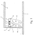
- Fig. 1 shows a in a highly schematic form Room 1 of a building covered by a floor 2, a ceiling 3 and a wall 4 surrounding it on all sides is bounded.
- a wall 4 In the wall 4 is at one point an open door or gate opening 5 from the floor 2 extends to a lintel 6 that extends from the ceiling 3 is spaced.
- 1 is located on the right from the wall 4 the interior of the room, to the left of wall 4 is "outside".
- the first blower device 7 has an air outlet 9, which is next to the lintel 6 is directed down towards the bottom 2.
- the first one points further to the interior of the room Blower device 7 has an air inlet on its underside 11, over which it sucks in air, which then over the aforementioned air outlet 9 is blown out.
- the second blower device 8 has the same structure, but is built in mirror image, i.e. their air outlet 12 is further inside than you Air intake 13.
- blower devices are expediently 7 and 8 designed so that their air inlets 11, 13 or air outlets 9, 12 over the entire width of the door 5 extend. If not for design reasons is possible, there is also the possibility along the Lintel 6 several first blower devices 7 and to provide a plurality of second blower devices 8 next to one another, thus the width of all air outlets 9, 12 and Air inlets 11, 13 together approximately the width of the door 5 corresponds.
- the air roller 15 consists of a blown out of the air outlet 9 onto the floor 2 Airflow 15 that is near the bottom 2 at 17 in Is diverted towards the interior of the room and then as an ascending air flow 18 to the air inlet 11 returned, i.e. the air roller 15 circulates to the illustration in Fig. 1, clockwise while the air roller 14 due to the mirror image Arrangement of the blower device in the counterclockwise direction running.
- Your airflow 19 directed towards the floor 2 is the furthest towards the interior of the room or in other words farthest from door 5 and will at 21 in the direction of the door 5 to then redirected as an upward air flow 22 to the air inlet 13 to get back.
- the second Blower device 8 an air conditioning device contains the flow between the air inlet 13th and the air outlet 12 is arranged, the outside air passes 23 only after temperature and Moisture is set to corresponding values as Air flow 24 the interior of the room. So is also at negative pressure in room 1 through the new arrangement ensures that no outside air immediately without Conditioning reaches the interior of the room.
- the first blower device 7 does not need an air conditioning device, because it is supposed to be the inner air roller shield from the outside. Furthermore, the amount of air per unit of time of the outer air roller less than with the inner one, which is adjacent to the room Air roller.
- 1 and 2 are the two blower devices 7 and 8 arranged directly next to each other. They can also be shared if necessary Housing be housed, the common Air intake between the ends of the case lying air outlets.
- the two blower devices 7 and 8 designed so are that for the outer air roller like that from the first Blower device 7 comes, no heating energy expended unlike the inner air roller. I.e. the two blower devices 7 and 8 are at least with regard to the heating of the air rollers in terms of ventilation essentially independent of each other.
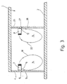
- FIG. 3 shows in addition to the immediately adjacent attachment of the two blower devices 7 and 8 .
- the room contains 1 at a distance from its outer wall 4 with the door opening 5 to Located inside the room is another wall 25 with a own door opening 26, which is on its upper edge by a Lintel 27 is limited.
- the first blower device 7 is, as in the embodiment of FIG. 1, oriented above the lintel 6 towards the interior of the room attached.
- the air outlet 9 is directly the Door opening 5 adjacent.
- the other blower device 8 is at a distance from the first blower device 7 on the wall 25 attached above the lintel 27, on that Side facing the outer wall 4.
- the second blower device 8 on the Partition 25 is attached such that its air outlet 12 creates an air curtain, the door opening 26 immediately is directed adjacent to the floor 2.
- two air rollers 14 and 15 with opposite Sense of rotation, so that the upward air flows directed to the blower devices 7 and 8 18 and 22 of the two air rollers 14 and 15 between these lie.
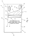
- Fig. 4 shows schematically the structure of the second Blower device 8. It has an all-round closed, rectangular sheet metal housing 31 with a Top 32, a bottom 33 and with a total four side walls 34 parallel to one another in pairs on. In the bottom 33 is next to the left Side wall 34 of the air inlet 13 in the form of a plurality notched longitudinal slots 35 through which the air can penetrate into the interior of the housing 31.
- An inner partition begins next to this air inlet 13 36, a chamber 37 inside the housing 31 departments.
- the partition 36 connects on the one hand to the Floor 33 next to the air inlet 13 and leads at a distance to the top 32 to the right side wall 34.
- the air outlet 12, for example in the form of a Grille cover, is also in the bottom 33 and connects the partitioned chamber 37 to the outside atmosphere. The arrangement is such that the air outlet 12 parallel to the right side wall 34 and runs adjacent to it.
- the partition 36 consists of a on the bottom 33 beginning ascending part 38 which is at a distance from the Top 32 ends and in a horizontal section 39 passes, which leads to the right side wall 34 this is largely airtight. Furthermore these two sections 38 and 39 extend the partition 36 perpendicular to the plane of the drawing between the side walls 34 parallel to the plane of the drawing.
- An intake funnel is located in the partition wall section 38 41, in which a fan 42 is arranged.
- a schematic in the chamber 37 indicated air conditioning device 43 is provided, which in the simplest case is a heat exchanger that the air flows through.
- a further partition 44 is arranged in the chamber 37, starting at the upper partition section 39 thence sloping down towards the right side wall 34 runs and above that in the Air outlet 12 seated grille 45 in a horizontal Section 46 passes over to its free end the right side wall 34 is attached.
- This will in the chamber 37 a further inner chamber 47 in terms of flow divided.
- This further chamber 47 serves as Air duct for generating an induction air jet using a high pressure blower 48 attached to an intake funnel 49 connected in the upper Partition section 39 is formed and into the inner Chamber 47 opens.
- the air from the inner chamber 37 passes through a Ejector nozzle 51, which is designed as a spherical nozzle and thus adjustable in the lower partition section 46 sits.
- blower device The operation of the blower device is like follows:
- air is passed through the air inlet 13 sucked in and under pressure into the chamber 37 promoted.
- the Blower 42 delivers air to the air conditioner 43 and impinges on the partition 44 on which it is deflected downward so that it passes through the grating 45 of the air outlet 12 can flow out.
- Another, air stream entering through the air inlet 13 flows past the blower 42 through the between the top 32 and the upper partition section 39 delimited Channel to the intake funnel 49.
- the high pressure fan 48 which is connected to the suction funnel 49 presses the air drawn in at relatively high pressure and thus a correspondingly high speed over the Ejector nozzle 51 to the outside, which is behind the grille 45 of the Air outlet 12 is arranged.
- the high speed of the induction jet emerging from the ejector 51 also serves as a support beam for stabilization of the air curtain and thus to that from the Air conditioning device 43 coming air with lower Air speed against the effect of the natural Convection to the floor 2 of the room 1 too create.
- Blower device is thus only a part of the intake Air conditioned, while the other part without Conditioning blown out at high speed becomes.
- a second air conditioning device to also provide the air that exits through the ejector nozzle 51 with respect to temperature and / or bring moisture to appropriate values.
- the Blower device 8 Because of the type of representation is shown in the Blower device 8 only one ejector 51 visible. However, it is easy to understand that several according to the width of the blower device 8 such ejector nozzles 51 are arranged side by side can.
- the first blower device 7 can with Except for the air conditioning device 43 as well be constructed like the second blower device 8.
Landscapes
- Engineering & Computer Science (AREA)
- Chemical & Material Sciences (AREA)
- Combustion & Propulsion (AREA)
- Mechanical Engineering (AREA)
- General Engineering & Computer Science (AREA)
- Ventilation (AREA)
- Duct Arrangements (AREA)
- Particle Accelerators (AREA)
- Curtains And Furnishings For Windows Or Doors (AREA)
- Toys (AREA)
- Air Bags (AREA)
- Separation By Low-Temperature Treatments (AREA)
Claims (13)
- Dispositif pour générer un rideau d'air dans le voisinage d'une porte (5, 26) d'un local (1) comportantcaractérisé par le fait que seul le second dispositif ventilateur (8) comporte un dispositif de conditionnement d'air (43) qui, sur le plan de l'écoulement, est disposé entre son entrée d'air (13) et sa sortie d'air (12) et à l'aide duquel la température et/ou l'humidité de l'air s'écoulant de l'entrée d'air (13) vers la sortie d'air (12) peuvent être réglées.un premier dispositif ventilateur (7) disposé au-dessus de la porte (5, 26), qui comprendau moins une sortie d'air (9) dans le voisinage de la porte (5, 26),au moins une entrée d'air (11) situé plus près de l'intérieur du local par rapport à la sortie d'air (9),et de la sortie d'air (9) duquel sort un flux d'air (16) dirigé du haut vers le bas qui, au niveau du sol (2), est dévié vers le haut en direction du dispositif ventilateur (7) et est au moins partiellement aspiré dans l'entrée d'air (11), de telle sorte qu'il se forme une première circulation d'air (14) dont la partie (18) dirigée vers le haut est éloignée de la porte (5, 26),un second dispositif ventilateur (8) comprenant au moins une sortie d'air (12) dirigée vers le sol (2) et au moins une entrée d'air (13)qui, par rapport au premier dispositif ventilateur (7), est disposé plus loin en direction de l'intérieur du local etest orienté de telle sorte que son entrée d'air (13) soit proche de l'entrée d'air (11) du premier dispositif ventilateur (7) afin de générer une circulation d'air (15) avec un sens de rotation opposé par rapport à la première circulation d'air (14), le flux d'air (18, 22) ascendant se formant entre les circulations d'air (14, 15),
- Dispositif selon la revendication 1, caractérisé par le fait que les deux dispositifs ventilateurs (7, 8) sont logés dans des carrosseries (31) propres, indépendantes l'une de l'autre.
- Dispositif selon la revendication 1, caractérisé par le fait que le premier dispositif ventilateur et le second dispositif ventilateur (7, 8) sont éloignés l'un de l'autre.
- Dispositif selon la revendication 1, caractérisé par le fait que les deux dispositifs ventilateurs (7, 8) sont logés dans une carrosserie commune.
- Dispositif selon la revendication 1, caractérisé par le fait que l'entrée d'air (11) du premier dispositif ventilateur (7) et l'entrée d'air (13) du second dispositif ventilateur (8) sont réunies en une entrée d'air commune.
- Dispositif selon la revendication 1, caractérisé par le fait que plusieurs premiers et seconds dispositifs ventilateurs (7, 8) sont disposés les uns à côté des autres sur la largeur de la porte (5, 26).
- Dispositif selon la revendication 1, caractérisé par le fait que les premier et second dispositifs ventilateurs (7, 8) présentent une construction identique, le cas échéant au dispositif de conditionnement d'air (43) près.
- Dispositif selon la revendication 1, caractérisé par le fait que le premier et/ou second dispositif ventilateur (7, 8) comprend un ventilateur d'air secondaire (48) pour générer un jet d'air d'induction ainsi qu'un ventilateur d'air primaire (42) qui génère un flux de grand volume et avec une vitesse plus faible que le ventilateur d'air secondaire (49).
- Dispositif selon la revendication 8, caractérisé par le fait que le ventilateur d'air secondaire (49) comporte au moins une buse d'éjecteur (51) qui fait partie de la sortie d'air (9, 12).
- Dispositif selon la revendication 1, caractérisé par le fait que le premier et/ou le second dispositif ventilateur (7, 8) comporte des ventilateurs propres qui, le cas échéant, peuvent être réglés indépendamment l'un de l'autre.
- Dispositif selon la revendication 1, caractérisé par le fait que le premier et/ou le second dispositif ventilateur (7, 8) comporte des dispositifs de guidage d'air propres, qui sont essentiellement indépendants l'un de l'autre.
- Dispositif selon la revendication 1, caractérisé par le fait que le premier et/ou le second dispositif ventilateur (7, 8) sur le plan aéraulique sont essentiellement indépendants l'un de l'autre.
- Dispositif selon la revendication 1, caractérisé par le fait que le dispositif de conditionnement d'air (43) est uniquement un dispositif de chauffage.
Applications Claiming Priority (2)
| Application Number | Priority Date | Filing Date | Title |
|---|---|---|---|
| DE4341784A DE4341784C2 (de) | 1993-12-08 | 1993-12-08 | Anordnung zur Erzeugung zweier gegenläufiger Luftschleier |
| DE4341784 | 1993-12-08 |
Publications (3)
| Publication Number | Publication Date |
|---|---|
| EP0657702A2 EP0657702A2 (fr) | 1995-06-14 |
| EP0657702A3 EP0657702A3 (fr) | 1997-02-05 |
| EP0657702B1 true EP0657702B1 (fr) | 2000-04-12 |
Family
ID=6504448
Family Applications (1)
| Application Number | Title | Priority Date | Filing Date |
|---|---|---|---|
| EP94119293A Expired - Lifetime EP0657702B1 (fr) | 1993-12-08 | 1994-12-07 | Dispositif pour la génération de deux rideaux d'air à sens de circulation opposée |
Country Status (4)
| Country | Link |
|---|---|
| EP (1) | EP0657702B1 (fr) |
| AT (1) | ATE191783T1 (fr) |
| DE (2) | DE4341784C2 (fr) |
| DK (1) | DK0657702T3 (fr) |
Cited By (1)
| Publication number | Priority date | Publication date | Assignee | Title |
|---|---|---|---|---|
| DE102010061007A1 (de) | 2010-04-29 | 2011-11-03 | Teddington Luftschleieranlagen Gmbh | Anordnung zur Abschottung eines Vorraums oder Windfangs |
Families Citing this family (6)
| Publication number | Priority date | Publication date | Assignee | Title |
|---|---|---|---|---|
| DE19932708A1 (de) * | 1999-07-16 | 2001-01-25 | Lks Luft Und Klimaservice Chri | Anordnung zur Erzeugung eines Luftschleiers an einer Tür zu einem Niedrigtemperaturraum |
| DE10029543B4 (de) * | 2000-06-15 | 2006-02-09 | Christiani Gmbh | Luftschleiergerät |
| DE20200246U1 (de) | 2002-01-09 | 2002-04-18 | Lks Israel Gmbh Klimatechnisch | Anordnung zur Erzeugung eines Luftschottes |
| DE10313108A1 (de) * | 2003-03-24 | 2004-10-07 | Lwt Luftwandtechnologie Gmbh | Luftstromvorrichtung mit Umlenkung des Luftstroms |
| DE10320490A1 (de) * | 2003-03-25 | 2004-10-14 | Kampmann Gmbh | Vorrichtung zur Erzeugung eines Luftschleiers |
| DE102010007295A1 (de) | 2010-02-08 | 2011-08-11 | Novoferm tormatic GmbH, 44309 | Antriebssteuerung und Verfahren zum Betrieb einer derartigen Antriebssteuerung |
Family Cites Families (5)
| Publication number | Priority date | Publication date | Assignee | Title |
|---|---|---|---|---|
| US3023688A (en) * | 1958-05-16 | 1962-03-06 | Jr Fred A Kramer | Air barrier |
| DE3004073A1 (de) * | 1980-02-05 | 1981-08-13 | TTL Tür + Torschleier lufttechnische Geräte GmbH, 7065 Winterbach | Raumlueftungseinrichtung |
| DE3050685C2 (de) * | 1980-02-05 | 1985-10-17 | TTL Tür + Torschleier lufttechnische Geräte GmbH, 7065 Winterbach | Einrichtung zum Erzeugen eines Torluftschleiers |
| DE9010016U1 (fr) * | 1990-07-02 | 1990-09-06 | Teddington Controls Gmbh, 5202 Hennef, De | |
| JPH04327736A (ja) * | 1991-04-30 | 1992-11-17 | Mitsubishi Heavy Ind Ltd | 流体吸引ノズル及び流体処理装置 |
-
1993
- 1993-12-08 DE DE4341784A patent/DE4341784C2/de not_active Expired - Fee Related
-
1994
- 1994-12-07 DE DE59409287T patent/DE59409287D1/de not_active Expired - Fee Related
- 1994-12-07 EP EP94119293A patent/EP0657702B1/fr not_active Expired - Lifetime
- 1994-12-07 AT AT94119293T patent/ATE191783T1/de not_active IP Right Cessation
- 1994-12-07 DK DK94119293T patent/DK0657702T3/da active
Cited By (1)
| Publication number | Priority date | Publication date | Assignee | Title |
|---|---|---|---|---|
| DE102010061007A1 (de) | 2010-04-29 | 2011-11-03 | Teddington Luftschleieranlagen Gmbh | Anordnung zur Abschottung eines Vorraums oder Windfangs |
Also Published As
| Publication number | Publication date |
|---|---|
| DE59409287D1 (de) | 2000-05-18 |
| DK0657702T3 (da) | 2000-07-31 |
| ATE191783T1 (de) | 2000-04-15 |
| DE4341784A1 (de) | 1995-06-14 |
| DE4341784C2 (de) | 1995-09-07 |
| EP0657702A2 (fr) | 1995-06-14 |
| EP0657702A3 (fr) | 1997-02-05 |
Similar Documents
| Publication | Publication Date | Title |
|---|---|---|
| EP1130331B1 (fr) | Procédé et dispositif de ventilation et de climatisation d'un local | |
| EP0657702B1 (fr) | Dispositif pour la génération de deux rideaux d'air à sens de circulation opposée | |
| DE69912031T2 (de) | Vorrichtung zum Belüften, Kühlen und/oder Beheizen eines Raumes | |
| DE1270771B (de) | Aus zwei Luftschleiern gebildete Luftsperre | |
| DE69912030T2 (de) | Luftkühlungsanordnung eines Raumes | |
| DE2033195C3 (de) | Luftaustrittseinrichtung für Klimaanlagen | |
| DE19525945C2 (de) | Verfahren und Vorrichtung zur Erzeugung behaglicher Raumluftzustände | |
| DE2328186A1 (de) | Einrichtung zum kuehlen und/oder erwaermen von raeumen | |
| DE3914242C2 (de) | Einrichtung zum Erwärmen und/oder Kühlen von Räumen | |
| DE19758139C2 (de) | Verfahren und Vorrichtung zur Klimatisierung eines Raumes | |
| EP1035385B1 (fr) | Procedé de thermoregulation d'un hall et dispositif pour la mise en oeuvre de ce procedé | |
| DE19834270A1 (de) | Ventilatorkonvektor | |
| EP1996870A1 (fr) | Convecteur de sol | |
| DE102008046361A1 (de) | Dezentrales lufttechnisches Gerät sowie lufttechnische Anlage mit einem derartigen Gerät | |
| AT408482B (de) | Vorrichtung zur verhinderung der vermischung zweier luftmengen | |
| DE3523937A1 (de) | Torluftschleieranlage | |
| EP3837475B1 (fr) | Système de gaine de pression, appareil de pression différentielle et bâtiment | |
| DE2809611A1 (de) | Verfahren zum lueften von raeumen sowie lueftungsvorrichtung zur durchfuehrung des verfahrens | |
| DE4016078C1 (fr) | ||
| DE3050685C2 (de) | Einrichtung zum Erzeugen eines Torluftschleiers | |
| DE2627727B2 (de) | Fenster mit zwei im Abstand hintereinander angeordneten Rahmen | |
| DE3025342A1 (de) | Vorrichtung zur belueftung von arbeitsraeumen, insbesondere von fabrikhallen | |
| DE3832915A1 (de) | Reinraum | |
| DE3806903A1 (de) | Verfahren zur klimatisierung von raeumen sowie klimatisierungssystem zur durchfuehrung des verfahrens | |
| DE2736837A1 (de) | Vorrichtung zum abtrennen von raeumen mittels bewegter luftschichten |
Legal Events
| Date | Code | Title | Description |
|---|---|---|---|
| PUAI | Public reference made under article 153(3) epc to a published international application that has entered the european phase |
Free format text: ORIGINAL CODE: 0009012 |
|
| AK | Designated contracting states |
Kind code of ref document: A2 Designated state(s): AT BE CH DE DK FR GB LI LU NL SE |
|
| PUAL | Search report despatched |
Free format text: ORIGINAL CODE: 0009013 |
|
| AK | Designated contracting states |
Kind code of ref document: A3 Designated state(s): AT BE CH DE DK FR GB LI LU NL SE |
|
| 17P | Request for examination filed |
Effective date: 19970125 |
|
| 17Q | First examination report despatched |
Effective date: 19980806 |
|
| GRAG | Despatch of communication of intention to grant |
Free format text: ORIGINAL CODE: EPIDOS AGRA |
|
| GRAG | Despatch of communication of intention to grant |
Free format text: ORIGINAL CODE: EPIDOS AGRA |
|
| GRAH | Despatch of communication of intention to grant a patent |
Free format text: ORIGINAL CODE: EPIDOS IGRA |
|
| GRAH | Despatch of communication of intention to grant a patent |
Free format text: ORIGINAL CODE: EPIDOS IGRA |
|
| GRAA | (expected) grant |
Free format text: ORIGINAL CODE: 0009210 |
|
| AK | Designated contracting states |
Kind code of ref document: B1 Designated state(s): AT BE CH DE DK FR GB LI LU NL SE |
|
| REF | Corresponds to: |
Ref document number: 191783 Country of ref document: AT Date of ref document: 20000415 Kind code of ref document: T |
|
| REG | Reference to a national code |
Ref country code: CH Ref legal event code: NV Representative=s name: KIRKER & CIE SA Ref country code: CH Ref legal event code: EP |
|
| ET | Fr: translation filed | ||
| REF | Corresponds to: |
Ref document number: 59409287 Country of ref document: DE Date of ref document: 20000518 |
|
| GBT | Gb: translation of ep patent filed (gb section 77(6)(a)/1977) |
Effective date: 20000519 |
|
| REG | Reference to a national code |
Ref country code: DK Ref legal event code: T3 |
|
| PGFP | Annual fee paid to national office [announced via postgrant information from national office to epo] |
Ref country code: GB Payment date: 20001123 Year of fee payment: 7 |
|
| PGFP | Annual fee paid to national office [announced via postgrant information from national office to epo] |
Ref country code: NL Payment date: 20001127 Year of fee payment: 7 |
|
| PGFP | Annual fee paid to national office [announced via postgrant information from national office to epo] |
Ref country code: DK Payment date: 20001201 Year of fee payment: 7 |
|
| PGFP | Annual fee paid to national office [announced via postgrant information from national office to epo] |
Ref country code: FR Payment date: 20001204 Year of fee payment: 7 Ref country code: SE Payment date: 20001204 Year of fee payment: 7 |
|
| PGFP | Annual fee paid to national office [announced via postgrant information from national office to epo] |
Ref country code: LU Payment date: 20001205 Year of fee payment: 7 |
|
| PGFP | Annual fee paid to national office [announced via postgrant information from national office to epo] |
Ref country code: BE Payment date: 20001207 Year of fee payment: 7 |
|
| PLBE | No opposition filed within time limit |
Free format text: ORIGINAL CODE: 0009261 |
|
| STAA | Information on the status of an ep patent application or granted ep patent |
Free format text: STATUS: NO OPPOSITION FILED WITHIN TIME LIMIT |
|
| 26N | No opposition filed | ||
| PG25 | Lapsed in a contracting state [announced via postgrant information from national office to epo] |
Ref country code: LU Free format text: LAPSE BECAUSE OF NON-PAYMENT OF DUE FEES Effective date: 20011207 Ref country code: GB Free format text: LAPSE BECAUSE OF NON-PAYMENT OF DUE FEES Effective date: 20011207 Ref country code: DK Free format text: LAPSE BECAUSE OF NON-PAYMENT OF DUE FEES Effective date: 20011207 |
|
| PG25 | Lapsed in a contracting state [announced via postgrant information from national office to epo] |
Ref country code: SE Free format text: LAPSE BECAUSE OF NON-PAYMENT OF DUE FEES Effective date: 20011208 |
|
| PG25 | Lapsed in a contracting state [announced via postgrant information from national office to epo] |
Ref country code: BE Free format text: LAPSE BECAUSE OF NON-PAYMENT OF DUE FEES Effective date: 20011231 |
|
| REG | Reference to a national code |
Ref country code: GB Ref legal event code: IF02 |
|
| BERE | Be: lapsed |
Owner name: TUR + TORLUFTSCHLEIER LUFTTECHNISCHE GERATE G.M.B. Effective date: 20011231 |
|
| PG25 | Lapsed in a contracting state [announced via postgrant information from national office to epo] |
Ref country code: NL Free format text: LAPSE BECAUSE OF NON-PAYMENT OF DUE FEES Effective date: 20020701 |
|
| EUG | Se: european patent has lapsed |
Ref document number: 94119293.2 |
|
| GBPC | Gb: european patent ceased through non-payment of renewal fee |
Effective date: 20011207 |
|
| PG25 | Lapsed in a contracting state [announced via postgrant information from national office to epo] |
Ref country code: FR Free format text: LAPSE BECAUSE OF NON-PAYMENT OF DUE FEES Effective date: 20020830 |
|
| NLV4 | Nl: lapsed or anulled due to non-payment of the annual fee |
Effective date: 20020701 |
|
| REG | Reference to a national code |
Ref country code: DK Ref legal event code: EBP |
|
| REG | Reference to a national code |
Ref country code: FR Ref legal event code: ST |
|
| PGFP | Annual fee paid to national office [announced via postgrant information from national office to epo] |
Ref country code: CH Payment date: 20081223 Year of fee payment: 15 |
|
| PGFP | Annual fee paid to national office [announced via postgrant information from national office to epo] |
Ref country code: AT Payment date: 20081216 Year of fee payment: 15 |
|
| PGFP | Annual fee paid to national office [announced via postgrant information from national office to epo] |
Ref country code: DE Payment date: 20081230 Year of fee payment: 15 |
|
| REG | Reference to a national code |
Ref country code: CH Ref legal event code: PL |
|
| PG25 | Lapsed in a contracting state [announced via postgrant information from national office to epo] |
Ref country code: AT Free format text: LAPSE BECAUSE OF NON-PAYMENT OF DUE FEES Effective date: 20091207 |
|
| PG25 | Lapsed in a contracting state [announced via postgrant information from national office to epo] |
Ref country code: LI Free format text: LAPSE BECAUSE OF NON-PAYMENT OF DUE FEES Effective date: 20091231 Ref country code: CH Free format text: LAPSE BECAUSE OF NON-PAYMENT OF DUE FEES Effective date: 20091231 |
|
| PG25 | Lapsed in a contracting state [announced via postgrant information from national office to epo] |
Ref country code: DE Free format text: LAPSE BECAUSE OF NON-PAYMENT OF DUE FEES Effective date: 20100701 |