EP0655263B1 - Mehrzweck-Trainingsgerät - Google Patents
Mehrzweck-Trainingsgerät Download PDFInfo
- Publication number
- EP0655263B1 EP0655263B1 EP94117411A EP94117411A EP0655263B1 EP 0655263 B1 EP0655263 B1 EP 0655263B1 EP 94117411 A EP94117411 A EP 94117411A EP 94117411 A EP94117411 A EP 94117411A EP 0655263 B1 EP0655263 B1 EP 0655263B1
- Authority
- EP
- European Patent Office
- Prior art keywords
- shaft
- machine according
- exercise machine
- support
- attachment
- Prior art date
- Legal status (The legal status is an assumption and is not a legal conclusion. Google has not performed a legal analysis and makes no representation as to the accuracy of the status listed.)
- Expired - Lifetime
Links
Images


Classifications
-
- A—HUMAN NECESSITIES
- A63—SPORTS; GAMES; AMUSEMENTS
- A63B—APPARATUS FOR PHYSICAL TRAINING, GYMNASTICS, SWIMMING, CLIMBING, OR FENCING; BALL GAMES; TRAINING EQUIPMENT
- A63B21/00—Exercising apparatus for developing or strengthening the muscles or joints of the body by working against a counterforce, with or without measuring devices
- A63B21/06—User-manipulated weights
-
- A—HUMAN NECESSITIES
- A63—SPORTS; GAMES; AMUSEMENTS
- A63B—APPARATUS FOR PHYSICAL TRAINING, GYMNASTICS, SWIMMING, CLIMBING, OR FENCING; BALL GAMES; TRAINING EQUIPMENT
- A63B21/00—Exercising apparatus for developing or strengthening the muscles or joints of the body by working against a counterforce, with or without measuring devices
- A63B21/00058—Mechanical means for varying the resistance
- A63B21/00065—Mechanical means for varying the resistance by increasing or reducing the number of resistance units
-
- A—HUMAN NECESSITIES
- A63—SPORTS; GAMES; AMUSEMENTS
- A63B—APPARATUS FOR PHYSICAL TRAINING, GYMNASTICS, SWIMMING, CLIMBING, OR FENCING; BALL GAMES; TRAINING EQUIPMENT
- A63B21/00—Exercising apparatus for developing or strengthening the muscles or joints of the body by working against a counterforce, with or without measuring devices
- A63B21/00058—Mechanical means for varying the resistance
- A63B21/00069—Setting or adjusting the resistance level; Compensating for a preload prior to use, e.g. changing length of resistance or adjusting a valve
- A63B21/00072—Setting or adjusting the resistance level; Compensating for a preload prior to use, e.g. changing length of resistance or adjusting a valve by changing the length of a lever
-
- A—HUMAN NECESSITIES
- A63—SPORTS; GAMES; AMUSEMENTS
- A63B—APPARATUS FOR PHYSICAL TRAINING, GYMNASTICS, SWIMMING, CLIMBING, OR FENCING; BALL GAMES; TRAINING EQUIPMENT
- A63B21/00—Exercising apparatus for developing or strengthening the muscles or joints of the body by working against a counterforce, with or without measuring devices
- A63B21/00196—Exercising apparatus for developing or strengthening the muscles or joints of the body by working against a counterforce, with or without measuring devices using pulsed counterforce, e.g. vibrating resistance means
-
- A—HUMAN NECESSITIES
- A63—SPORTS; GAMES; AMUSEMENTS
- A63B—APPARATUS FOR PHYSICAL TRAINING, GYMNASTICS, SWIMMING, CLIMBING, OR FENCING; BALL GAMES; TRAINING EQUIPMENT
- A63B21/00—Exercising apparatus for developing or strengthening the muscles or joints of the body by working against a counterforce, with or without measuring devices
- A63B21/02—Exercising apparatus for developing or strengthening the muscles or joints of the body by working against a counterforce, with or without measuring devices using resilient force-resisters
- A63B21/023—Wound springs
-
- A—HUMAN NECESSITIES
- A63—SPORTS; GAMES; AMUSEMENTS
- A63B—APPARATUS FOR PHYSICAL TRAINING, GYMNASTICS, SWIMMING, CLIMBING, OR FENCING; BALL GAMES; TRAINING EQUIPMENT
- A63B21/00—Exercising apparatus for developing or strengthening the muscles or joints of the body by working against a counterforce, with or without measuring devices
- A63B21/15—Arrangements for force transmissions
- A63B21/151—Using flexible elements for reciprocating movements, e.g. ropes or chains
- A63B21/153—Using flexible elements for reciprocating movements, e.g. ropes or chains wound-up and unwound during exercise, e.g. from a reel
-
- A—HUMAN NECESSITIES
- A63—SPORTS; GAMES; AMUSEMENTS
- A63B—APPARATUS FOR PHYSICAL TRAINING, GYMNASTICS, SWIMMING, CLIMBING, OR FENCING; BALL GAMES; TRAINING EQUIPMENT
- A63B21/00—Exercising apparatus for developing or strengthening the muscles or joints of the body by working against a counterforce, with or without measuring devices
- A63B21/15—Arrangements for force transmissions
- A63B21/151—Using flexible elements for reciprocating movements, e.g. ropes or chains
- A63B21/154—Using flexible elements for reciprocating movements, e.g. ropes or chains using special pulley-assemblies
- A63B21/155—Cam-shaped pulleys or other non-uniform pulleys, e.g. conical
-
- A—HUMAN NECESSITIES
- A63—SPORTS; GAMES; AMUSEMENTS
- A63B—APPARATUS FOR PHYSICAL TRAINING, GYMNASTICS, SWIMMING, CLIMBING, OR FENCING; BALL GAMES; TRAINING EQUIPMENT
- A63B21/00—Exercising apparatus for developing or strengthening the muscles or joints of the body by working against a counterforce, with or without measuring devices
- A63B21/16—Supports for anchoring force-resisters
- A63B21/169—Supports for anchoring force-resisters for anchoring on or against a wall
-
- A—HUMAN NECESSITIES
- A63—SPORTS; GAMES; AMUSEMENTS
- A63B—APPARATUS FOR PHYSICAL TRAINING, GYMNASTICS, SWIMMING, CLIMBING, OR FENCING; BALL GAMES; TRAINING EQUIPMENT
- A63B21/00—Exercising apparatus for developing or strengthening the muscles or joints of the body by working against a counterforce, with or without measuring devices
- A63B21/02—Exercising apparatus for developing or strengthening the muscles or joints of the body by working against a counterforce, with or without measuring devices using resilient force-resisters
- A63B21/04—Exercising apparatus for developing or strengthening the muscles or joints of the body by working against a counterforce, with or without measuring devices using resilient force-resisters attached to static foundation, e.g. a user
- A63B21/0407—Anchored at two end points, e.g. installed within an apparatus
- A63B21/0421—Anchored at two end points, e.g. installed within an apparatus the ends moving relatively by a pivoting arrangement
-
- A—HUMAN NECESSITIES
- A63—SPORTS; GAMES; AMUSEMENTS
- A63B—APPARATUS FOR PHYSICAL TRAINING, GYMNASTICS, SWIMMING, CLIMBING, OR FENCING; BALL GAMES; TRAINING EQUIPMENT
- A63B2208/00—Characteristics or parameters related to the user or player
- A63B2208/02—Characteristics or parameters related to the user or player posture
- A63B2208/0204—Standing on the feet
Definitions
- the invention relates to a multi-purpose training device for fitness and strength training, which is designed as an exercise bike for domestic training.
- Training devices for muscle training are known in large numbers, see for example DE-C-176 916. They consist of a frame with devices for supporting the body or individual body parts as well as a movable mechanism which can be actuated by muscle power and which is loaded by spring force or a counterweight or contains a brake generating a resistance.
- training devices are usually only designed for a very specific single function or at most for a small number of functions for training very specific muscle areas, since such studios have a plurality of devices that are designed by the exercising persons are used one after the other. These devices are also quite large and require a corresponding amount of space.
- the known training devices available for home training include bicycle and rowing machines, training racks without a movable mechanism for gymnastics or barbell exercises, and also more demanding larger devices with two or three functions, but which are essentially constructed according to the concept of studio equipment and are accordingly large, bulky and are expensive.
- the invention has for its object to provide a multi-purpose training device for home training use, which is characterized on the one hand by a large variety of uses, that is, for training as many muscle parts of the body, but on the other hand by a small footprint.
- the training device according to the invention is designed in such a way that it manages with a minimal footprint by being able to be positioned at a short distance from a wall and can be fastened to the wall, whereas fastening to the floor and thus drilling of holes in the flooring is unnecessary.
- the device can be converted for various types of exercises, and the resistance can also be changed several times without tools in just a few simple steps.
- the device has a simple but sensible design and is therefore very compact, has a low weight and is inexpensive, but enables training of practically all muscle parts of the body.
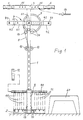
- FIGS 1 to 3 show the essential structure of the multipurpose training device according to the invention.
- the frame of the device consists of a support in the form of a column 1 with a foot 2, an upper cross member 3 and a horizontal frame 4 arranged below the cross member 3.
- the column 1 designed as a simple rod in the illustrated embodiment is advantageous in every respect, but the support could also be constructed in a different way, for example as a standing flat frame.
- a differently designed framework could be used which fulfills the same functions.
- the foot 2 is designed here as an angle profile running transversely to the column 1, but it can also be designed as a base plate or have spacers running towards the wall and, if necessary, wall fastening angles for additional wall fastening.
- the upper cross bar 3 is provided on both sides with handles 5, which can be arranged on the cross bar 3 so that they can be removed and, if necessary, adjustable in their lateral distance from the column 1. These handles 5 are used so that the user of the device can hold or support certain exercises with one hand or both hands on the frame of the training device.
- the horizontal frame 4 as the plan view shows, has a rectangular basic shape and consists of a front spar 41 running parallel to the cross bar 3 and crossing the column 1, a rear spar 42 parallel to it, that is to say transverse to the column 1 at a distance behind it, and two connecting bars 43 running between the bars 41 and 42.
- the rear frame spar 42 is longer than the front frame spar 41 and has end parts projecting over the connecting spars 43, which are each provided with a hole for the screw 44 for wall mounting.
- the frame 4 thus serves on the one hand as a wall fastening element for the frame and determines the distance of the column 1 from the wall.
- the main function of the frame is, however, the inclusion and mounting of a horizontal shaft 6 which runs between the rear frame spar 42 and the front frame spar 41 centrally, that is to say through the crossover region between the front frame spar 41 and the column 1 and which is rotatably mounted in the frame 4 eccentric wheel 7 connected therewith in a rotationally fixed manner, and is guided forward through the intersection area between the front frame spar 41 and the column 1 and ends in a coupling shaft 61 projecting forward over the column 1, which can be used for rotationally fixed attachment, as described below
- Training lever 20 or 30 is used.
- An attached training lever is shown in FIG. 5, but is omitted in FIG. 1 for the sake of clarity.
- the coupling shaft 61 is designed as a polygonal rod, while the training lever to be attached has a corresponding internal polygon, but it goes without saying that the coupling shaft can alternatively also be designed as a sleeve with an internal polygon, in which a corresponding one arranged on the training lever Polygonal pin is insertable.
- the coupling shaft is a hexagonal rod, so that a training lever to be plugged on can optionally be inserted into one of several positions, each having 60 ° angular distances, but on the other hand a wear-resistant, rotationally fixed connection between the coupling shaft and training lever can be ensured.
- a square or octagonal rod could also be used, but the square rod has the disadvantage of a smaller number of possible angular positions of the training lever to be attached and an octagonal or polygonal rod has the disadvantage of a less robust, non-rotatable connection between the coupling shaft and the training lever.
- the eccentric wheel 7 sits on the shaft 6 in such a way that the eccentric wheel diameter which intersects the shaft 6 runs approximately horizontally in the idle state. For reasons of accident safety, it is preferably designed as a full pane.
- the eccentric wheel 7 is connected via a traction element, namely a chain 8, to a carriage 9 guided on the column 1, the chain 8 being passed between two guide rollers 10 arranged below the frame 4 in the upper region of the column 1, so that below the Guide rollers 10, the chain 8 always runs parallel, ie vertically, along the back of the column 1.
- the carriage 9 guided on the column 1 has a cross bar 91 which, like the angular profile forming the foot 2, extends symmetrically on both sides of the column 1. Between the cross bar 91 and the foot 2 are in pairs Helical tension springs 11 arranged symmetrically with respect to the column 1, one spring end of which is in each case attached to the crossbar 91 and the other spring end of which is in each case attached to the vertical angle profile leg of the foot 2.
- 6 tension springs 11, that is to say three pairs of springs, are shown, but more or fewer pairs of springs can also be provided.
- the arrangement of the springs in pairs serves, as can be readily seen, for the symmetrical and tilt-free loading of the slide 9.
- one or more pairs of springs can optionally be hooked in, in order to variably adjust the resistance to be overcome.
- the cross bar 91 is preferably designed as a round bar and can be the same length or longer than the base 2, and instead of the springs 11, weight plates 12 can optionally also be placed symmetrically on the ends of the cross bar 91 on both sides. Of course, especially if the crossbar 91 is longer than the base 2, pairs of springs and weight plates can be combined with one another.
- the meaning of the eccentric wheel 7 lies in the fact that when a training lever is attached to the coupling shaft 61, it is non-linear to the angle of rotation The course of the slide stroke of the slide 9 and thus produces a non-linear force curve, which is adapted to the anatomical conditions in the contraction curve of a muscle to be trained.
- a number of square pegs 14 projecting forward are arranged somewhat below the point of intersection of the front frame spar 41 with the column 1, which serve for the optional attachment of the device parts described below.
- three such square pins 14 are provided which, as shown, have angular orientations offset by 45 ° in each case.
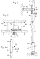
- FIGS. 4a and 4b show two different training levers 20 and 30, which can optionally be plugged onto the coupling shaft 61, the training lever 20 being equipped with a grip piece 21 for gripping with one hand for training the arms, while the training lever 30 is equipped with a larger one, at right angles protruding roller body 31 is provided, which is provided for a leg or neck to move this training lever.
- Both training levers 20 and 30 are each telescopically extendable and consist of a rod 22 or 32 with a hexagon socket 23 or 33 for plugging onto the coupling shaft 61, and of a sleeve 24 or 34 which can be displaced on the rod and on which the grip piece 21 or the roller body 31 is arranged and which is provided with a locking member 25 or 35 for locking in the selected position on the rod, as shown, 22 or 32, the locking member as a clamping screw for stepless adjustment of the sleeve on the rod or possibly also as a pin for stepped length adjustment of the training lever in cooperation with a number of corresponding bores in the rod.
- the grip piece 21 has a short crank arm 26 is rotatably connected to the sleeve 22 to provide the possibility of an automatic length compensation during the lever rotation if the natural trajectory of the hand gripping the handle during a training exercise should not exactly coincide with the circular path of the training lever or the crank pivot point.
- FIGS. 4c and 4d show push-on devices for optional attachment to the square pin 14, namely an arm support cushion 40 with an inner square 41 in FIG. 4c and a leaning cushion 50 in FIG. 4d.
- the backrest pad 50 is again roll-shaped, so that it can be used from all sides to lean against the body with hips, buttocks, back or abdominal area during certain exercises and has a cranked handle 51, with an inner square 52 so that it, depending on the attachment to the one or other lateral square pin 14 on the frame, located on one side or the other side of the frame center.
- the conditions namely the arrangement of the square pin 14 on the frame, the formation of the arm support pad 40 and the cranking of the stem 51 of the rest pad 50 are selected so that when the user, for example when arm wrestling, rests the elbow on the arm support pad to carry the arm to push the training lever sideways, the arm pivot point coincides approximately with the axis of rotation of the shaft 6, and if the user, for example, supports the abdominal support against the backrest pad 50 in order to move the training lever with the neck bent, for example, with the neck, the body pivot point in turn approximately coincides with the axis of rotation 6.
- a particular advantage of the training device is that working strokes of the training levers are possible both clockwise and anti-clockwise, so the device can be used to train both arms, both legs, arm wrestling on one side or the other, etc. without, apart from repositioning the training lever on the clutch shaft 61 in Orientation to the left or right, no conversion measures on the device itself are necessary.
- the only handle to be carried out during the transition from the right-hand working stroke (corresponding to the illustration in FIG. 1 with the upper chain end guided to the left side of the eccentric wheel 7) is to change the eccentric wheel 7 by swiveling through 180 °, ie by swiveling the one shown in the illustration according to FIG.
- the training device can be brought into a pretensioned position by rotating the eccentric wheel 7 by a certain range by means of a training lever attached to the coupling shaft 61 and thereby lifting the slide 9 under tension of the spring 11 by a corresponding amount, after which the stop pin 16 is inserted into the corresponding bore 15, on which the training lever now rests in the pretensioned position and is locked against a return stroke.
- the training can then start from the prestressed position.
- the training device is preferably assigned a step stool 60 and the height of the frame is adjusted so that the user stands in front of the device for certain exercises, such as arm wrestling, for example for leg exercises but stands on the stool for training. This makes swiveling leg exercises possible without the foot colliding with the floor.
- Such an attachable handle device 70 is shown in FIG. 4e and has a horizontal shaft 71, a vertical spar 72 and two handles 73 which are arranged on both spar ends and can be used optionally.
- the shaft 71 can optionally be inserted laterally left or right into the upper frame spar or the left or right lateral end of the front spar 41 of the frame 4 can also be inserted.
- Fig. 5 shows an enlarged view of the upper part of the device in the state prepared for arm wrestling.
- the training lever 20 (FIG. 4a) is attached to the coupling shaft 61, in such a way that it projects somewhat obliquely to the top right.
- a stop pin 16 is inserted into one of the bores 15 of the upper cross member 3, against which the left edge surface of the training lever 20 bears.
- the device is pre-tensioned, ie the eccentric wheel is already partially rotated, so that the training lever is already under tension in the position shown and is relaxed by the stop pin 16 against a return movement into the relaxed position Position is locked.
- the lean-on cushion 50 is attached to the left-hand square pin 14 in FIG. 1, which is rotated by 45 ° with respect to the central square pin, so that the cranked stem 51 of the armrest cushion runs obliquely downward to the left and thus the lean-on cushion 50 is located below the armrest cushion 40 to the left of column 1.
- the training lever 20 can be tensioned in a clockwise direction, so that the device is now prepared for arm wrestling with the left arm of the user standing in front of the device, who is leaning laterally against the backrest pad 50 with the left hip region, supporting the elbow on the arm support pad 40 and with the Faust grips the handle 51 of the training lever 20 to push it clockwise.
- the described training device offers the possibility of training the inner thigh and outer thigh muscles of both legs, the buttocks and abdominal muscles, the lumbar and back muscles, the front and rear thigh muscles, the front rear upper arm muscles, and the shoulder and chest muscles.
- the height of the column 1 of the device can be adjusted by preferably providing a telescopic column section above the slide movement path, in which locking means, e.g. Bores and socket pins are provided for fixing at the desired height.
- locking means e.g. Bores and socket pins are provided for fixing at the desired height.
- the foot 2 does not need to be attached to the floor. However, it is advantageous to apply an anti-slip coating on the underside of the foot.
Landscapes
- Health & Medical Sciences (AREA)
- Life Sciences & Earth Sciences (AREA)
- Biophysics (AREA)
- Orthopedic Medicine & Surgery (AREA)
- General Health & Medical Sciences (AREA)
- Physical Education & Sports Medicine (AREA)
- Rehabilitation Tools (AREA)
- Control Of Multiple Motors (AREA)
- Forklifts And Lifting Vehicles (AREA)
- Jib Cranes (AREA)
Description
- Die Erfindung betrifft ein Mehrzweck-Trainingsgerät für Fitness- und Krafttraining, das als Heimtrainer für häusliches Training konzipiert ist.
- Trainingsgeräte für Muskeltraining sind in großer Zahl bekannt, siehe zum Beispiel DE-C-176 916. Sie bestehen aus einem Gestell mit Einrichtungen zum Abstützen des Körpers oder einzelner Körperteile sowie aus einem durch Muskelkraft betätigbaren beweglichen Mechanismus, der durch Federkraft oder ein Gegengewicht belastet ist oder eine einen Widerstand erzeugende Bremse enthält.
- Für den professionellen Bereich, also für Fitness- und Krafttrainingsstudios konzipierte Trainingsgeräte sind üblicherweise jeweils nur für eine ganz bestimmte einzige Funktion oder höchstens für eine kleine Anzahl von Funktionen zum Trainieren ganz bestimmter Muskelpartien ausgebildet, da solche Studios über eine Mehrzahl von Geräten verfügen, die von den trainierenden Personen nacheinander benutzt werden. Diese Geräte sind auch ziemlich groß und erfordern einen entsprechenden Platzbedarf.
- Die für das Heimtraining verfügbaren bekannten Trainingsgeräte umfassen Fahrad- und Rudergeräte, Trainingsgestelle ohne beweglichen Mechanismus für Gymnastik- oder Hantelübungen, und auch anspruchsvollere größere Geräte mit zwei oder drei Funktionen, die aber im wesentlichen nach dem Konzept der Studiogeräte aufgebaut und entsprechend groß, sperrig und teuer sind.
- Der Erfindung liegt die Aufgabe zugrunde, ein Mehrzweck-Trainingsgerät für den Heimtrainingsgebrauch zu schaffen, das sich einerseits durch große Vielfalt der Benutzungsmöglichkeit, also für das Trainieren möglichst vieler Muskelpartien des Körpers, andererseits aber durch einen nur geringen Platzbedarf auszeichnet.
- Diese Aufgabe wird gemäß der Erfindung durch das im Anspruch 1 angegebene Mehrzweck-Trainingsgerät gelöst.
- Zweckmäßige Weiterbildungen des erfindungsgemäßen Geräts sind Gegenstand der Unteransprüche.
- Wie sich aus der folgenden Beispielsbeschreibung noch deutlicher ergibt, ist das erfindungsgemäße Trainingsgerät so konzipiert, daß es mit minimaler Stellfläche auskommt, indem es mit geringem Abstand vor einer Wand postierbar ist und an der Wand befestigbar ist, wohingegen eine Befestigung am Boden und damit das Bohren von Löchern in den Bodenbelag entbehrlich ist. Mittels einfacher werkzeugloser Aufstecktechnik ist das Gerät für verschiedenartige Übungen umrüstbar, und der Widerstand ist ebenfalls ohne Werkzeug mit wenigen Handgriffen mehrfach veränderbar. Das Gerät ist einfach, aber sinnvoll aufgebaut und damit sehr kompakt, hat ein geringes Gewicht und ist kostengünstig, ermöglicht aber ein Trainieren praktisch sämtlicher Muskelpartien des Körpers.
- Ein Ausführungsbeispiel des erfindungsgemäßen Trainingsgeräts wird nachstehend unter Bezugnahme auf die anliegenden Zeichnungen mehr im einzelnen beschrieben, in welchen zeigt:
- Fig. 1
- Das Gerät in Frontansicht,
- Fig. 2
- das Gerät in Seitenansicht,
- Fig. 3
- das Gerät in Draufsicht,
- die Fig. 4 bis 4e
- Ansichten von verschiedenen wahlweise zu benutzenden Trainingshebeln und ansteckbaren Geräteteilen, und
- Fig. 5
- ein Ansicht ähnlich Fig. 1 mit einem aufgesteckten Trainingshebel, aufgestecktem Armstützpolster und aufgestecktem Anlehnpolster.
- Die Figuren 1 bis 3 zeigen den wesentlichen Aufbau des erfindungsgemäßen Mehrzweck-Trainingsgeräts.
- Die Zeichnungen sind nicht unbedingt maßstäblich; wo es zur klaren Darstellung notwendig ist, sind Bauteile etwas vergrößert dargestellt. In der Draufsicht nach Fig. 3 ist der Übersichtlichkeit halber alles, was zum Fußbereich des Gerätes gehört, weggelassen.
- Das Gestell des Geräts besteht aus einer Stütze in Form einer Säule 1 mit einem Fuß 2, einem oberen Querholm 3 und einem unterhalb des Ouerholms 3 angeordneten horizontalen Rahmen 4.
- Die als einfacher Stab ausgebildete Säule 1 bei dem dargestellten Ausführungsbeispiel ist in jeder Hinsicht vorteilhaft, jedoch könnte die Stütze auch in andere Weise, beispielsweise als stehender ebener Rahmen aufgebaut sein. Ebenso könnte anstelle des oberen Querholms und des dargestellten horizontalen Rahmens bei dem Ausführungsbeispiel ein anders gestaltetes Rahmenwerk Anwendung finden, das die gleichen Funktionen erfüllt.
- Der Fuß 2 ist hier als quer zur Säule 1 verlaufendes Winkelprofil ausgebildet, es kann aber auch als Fußplatte ausgebildet sein oder zur Wand hin verlaufende Abstandhalter und ggf. Wandbefestigungswinkel zur zusätzlichen Wandbefestigung haben.
- Der obere Querholm 3 ist beiderseits mit Handgriffen 5 versehen, die abnehmbar und ggf. in ihrem seitlichem Abstand zur Säule 1 verstellbar am Querholm 3 angeordnet sein können. Diese Handgriffe 5 dienen dazu, daß der Benutzer des Geräts sich bei bestimmten Übungen mit einer Hand oder beiden Händen am Gestell des Trainingsgeräts festhalten bzw. abstützen kann.
- Der horizontale Rahmen 4 hat, wie die Draufsicht zeigt, eine rechteckige Grundform und besteht aus einem parallel zum Querholm 3 verlaufenden und die Säule 1 kreuzenden vorderen Holm 41, einem dazu parallelen hinteren, also mit Abstand hinterhalb der Säule 1 quer verlaufenden Holm 42, und zwei zwischen den Holmen 41 und 42 verlaufenden Verbindungsholmen 43.
- Der hintere Rahmenholm 42 ist länger als der vordere Rahmenholm 41 und weist beiderseits über die Verbindungsholme 43 überstehende Endteile auf, die jeweils mit einer Bohrung für die Schraube 44 zur Wandbefestigung versehen sind. Der Rahmen 4 dient damit einerseits als Wandbefestigungselement für das Gestell und bestimmt den Abstand der Säule 1 vor der Wand. Die Hauptfunktion des Rahmens ist aber die Aufnahme und Lagerung einer zwischen dem hinteren Rahmenholm 42 und dem vorderen Rahmenholm 41 mittig, d.h. durch den Kreuzungsbereich zwischen dem vorderen Rahmenholm 41 und der Säule 1 verlaufenden horizontalen Welle 6, die im Rahmen 4 drehbar gelagert ist, ein damit drehfest verbundenes Exzenterrad 7 trägt, und nach vorne durch den Kreuzungsbereich zwischen dem vorderen Rahmenholm 41 und der Säule 1 hindurch geführt ist und in einem nach vorne über die Säule 1 überstehenden Kupplungsschaft 61 endigt, der zum drehfesten Aufstecken wahlweise zu verwendender, nachstehend noch beschriebener Trainingshebel 20 bzw. 30 dient. Ein aufgesteckter Trainingshebel ist in Fig. 5 dargestellt, in Fig. 1 jedoch der Übersichtlichkeit halber weggelassen.
- Bei dem dargestellten Ausführungsbeispiel ist der Kupplungsschaft 61 als Vielkantstab ausgebildet, während der aufzusteckende Trainingshebel einen entsprechenden Innenvielkant aufweist, aber es versteht sich von selbst, daß der Kupplungsschaft alternativ auch als Muffe mit einem Innenvielkant ausgebildet sein kann, in welchen ein entsprechender, am Trainingshebel angeordneter Vielkantzapfen einsteckbar ist. Bei dem dargestellten Ausführungsbeispiel handelt es sich bei dem Kupplungsschaft um einen Sechskantstab, so daß ein aufzusteckender Trainingshebel wahlweise in eine von mehreren, jeweils 60°-Winkelabstände aufweisenden Positionen einsteckbar ist, andererseits aber eine verschleißfeste drehfeste Verbindung zwischen Kupplungsschaft und Trainingshebel gewährleistet werden kann. Grundsätzlich könnte auch ein Vierkant- oder Achtkantstab Anwendung finden, wobei aber der Vierkantstab den Nachteil einer geringeren Anzahl möglicher Winkelpositionen des aufzusteckenden Trainingshebels und ein Acht- oder Mehrkantstab den Nachteil einer weniger robusten drehfesten Verbindung zwischen Kupplungsschaft und Trainingshebel hat.
- Das Exzenterrad 7 sitzt so auf der Welle 6, daß der Exzenterraddurchmesser, welcher die Welle 6 schneidet, im Ruhezustand etwa horizontal verläuft. Es ist aus Gründen der Unfallsicherheit vorzugsweise als Vollscheibe ausgebildet.
- Das Exzenterrad 7 ist über ein Zugorgan, nämlich eine Kette 8, mit einem auf der Säule 1 geführten Schlitten 9 verbunden, wobei die Kette 8 zwischen zwei im oberen Bereich der Säule 1 unterhalb des Rahmens 4 angeordneten Führungsrollen 10 hindurchgeführt ist, so daß unterhalb der Führungsrollen 10 die Kette 8 stets parallel, also vertikal, entlang der Rückseite der Säule 1 verläuft.
- Der auf der Säule 1 geführte Schlitten 9 weist eine Querstange 91 auf, die sich ebenso wie das den Fuß 2 bildende Winkelprofil symmetrisch beiderseits der Säule 1 erstreckt. Zwischen der Querstange 91 und dem Fuß 2 sind paarweise symmetrisch mit Bezug auf die Säule 1 angeordnete Schraubenzugfedern 11 angeordnet, deren eines Federende jeweils an der Querstange 91 eingehängt und deren anderes Federende jeweils am vertikalen Winkelprofilschenkel des Fußes 2 eingehängt sind. Beim Ausführungsbeispiel sind 6 Zugfedern 11, also drei Federpaare dargestellt, jedoch können auch mehr oder weniger Federpaare vorgesehen sein. Die paarweise Anordnung der Federn dient, wie ohne weiteres ersichtlich ist, der symmetrischen und verkantungsfreien Belastung des Schlittens 9.
- Für das Training können nach Bedarf wahlweise ein oder mehr Federpaare eingehängt werden, um so die jeweils zu überwindende Widerstandskraft variabel einzustellen.
- Die Querstange 91 ist vorzugsweise als Rundstange ausgebildet und kann gleich lang oder länger wie der Fuß 2 sein, und anstelle der Federn 11 können wahlweise auch Gewichtsscheiben 12 symmetrisch auf die beiderseitigen Enden der Querstange 91 aufsteckbar sein. Selbstverständlich lassen sich zwar insbesonderen wenn die Querstange 91 länger als der Fuß 2 ist, Federpaare und Gewichtsscheiben nach Wahl miteinander kombinieren.
- Durch Drehen des Exzenterrads 7 über einen auf den Kupplungsschaft 61 aufgesteckten Trainingshebel, was nachstehend noch näher beschrieben wird, wird über die Kette 8 der Schlitten 9 unter Dehnung der Zugfedern 11 bzw. gegen die Gewichtskraft von auf die Querstange 91 aufgesteckten Gewichtsscheiben 12 nach oben angehoben. Zwischen dem unteren Ende des Schlittens 9 und dem Fuß 2 sind zweckmäßigerweise Gummipuffer 13 angeordnet, um einen möglichen Aufschlag des Schlittens 9 zu dämpfen. Es können natürlich auch andere geeignete Maßnahmen alternativ oder zusätzlich zu den Gummipuffern 13 zur Rückhubdämpfung des Schlittens 9 vorgesehen sein.
- Die Bedeutung des Exzenterrads 7 liegt darin, daß es beim Drehen eines auf den Kupplungsschaft 61 aufgesteckten Trainingshebels einen retaltiv zum Drehwinkel nichtlinearen Verlauf des Schlittenhubs des Schlitten 9 und somit einen nichtlinearen Kraftverlauf erzeugt, was den anatomischen Verhältnissen beim Kontraktionsverlauf eines zu trainierenden Muskels angepaßt ist.
- Etwas unterhalb der Kreuzungsstelle des vorderen Rahmenholms 41 mit der Säule 1 ist eine Anzahl von nach vorne überstehenden Vierkantzapfen 14 angeordnet, die zum wahlweisen Aufstecken von nachstehend noch beschriebenen Geräteteilen dienen. Beim dargestellten Ausführungsbeispiel sind drei solcher Vierkantzapfen 14 vorgesehen, die, wie dargestellt, um jeweils 45° versetzte winkelmäßige Orientierung haben.
- Die Figuren 4a und 4b zeigen zwei verschiedene, wahlweise auf den Kupplungsschaft 61 aufsteckbare Trainingshebel 20 bzw. 30, wobei der Trainingshebel 20 ein Griffstück 21 zum Ergreifen mit einer Hand für das Trainieren der Arme ausgestattet ist, während der Trainingshebel 30 mit einem größeren, rechtwinklig davon abstehenden Rollenkörper 31 ausgestattet ist, der für ein Anlegen der Beine oder des Nackens vorgesehen ist, um diesen Trainingshebel zu bewegen.
- Beide Trainingshebel 20 und 30 sind jeweils teleskopartig verlängerbar ausgebildet und bestehen aus einem Stab 22 bzw. 32 mit einem Innensechskant 23 bzw. 33 zum Aufstecken auf den Kupplungsschaft 61, und aus einer auf dem Stab verschiebbaren Hülse 24 bzw. 34, an welcher das Griffstück 21 bzw. der Rollenkörper 31 angeordnet ist und die mit einem Arretierorgan 25 bzw. 35 zum Feststellen in der gewählten Position auf dem Stab, wie dargestellt, 22 bzw. 32 versehen ist, wobei das Feststellorgan als Klemmschraube für stufenlose Verstellung der Hülse auf dem Stab oder möglicherweise auch als Steckstift für stufige Längenverstellung des Trainingshebels im Zusammenwirken mit einer Reihe entsprechender Bohrungen in dem Stab ausgebildet sein kann.
- Bei dem in Fig. 4a gezeigten Trainingshebel 20 ist wesentlich, daß das Griffstück 21 über einen kurzen Kurbelarm 26 drehbar mit der Hülse 22 verbunden ist, um die Möglichkeit eines selbsttätigen Längenausgleichs während der Hebeldrehbewegung zu schaffen, falls die natürliche Bewegungsbahn der den Handgriff erfassenden Hand bei einer Trainingsübung sich nicht genau mit der kreisbogenförmigen Bahn des Trainingshebels bzw. des Kurbelanlenkpunktes decken sollte.
- Die Figuren 4c und 4d zeigen Aufsteckgeräte zum wahlweise Aufstecken auf die Vierkantzapfen 14, nämlich in Fig. 4c ein Armstützpolster 40 mit Innenvierkant 41 und in Fig. 4d ein Anlehnpolster 50.
- Das Anlehnpolster 50 ist wiederum rollenförmig, so daß es von allen Seiten zum Anlehnen des Körpers mit Hüften, Gesäß, Rücken oder Bauchpartie während bestimmter Übungen benützt werden kann und hat einen gekröpften Stiel 51, mit Innenvierkant 52 so daß es, je nach Aufstecken auf den einen oder anderen seitlichen Vierkantzapfen 14 am Gestell, sich auf der einen Seite oder der anderen Seite der Gestellmitte befindet. Die Verhältnisse, nämlich die Anordnung der Vierkantzapfen 14 am Gestell, die Ausbildung des Armstützpolsters 40 und die Kröpfung des Stiels 51 des Anlehnpolsters 50 sind so gewählt, daß wenn der Benutzer, beispielsweise beim Armdrücken, den Ellbogen auf das Armstützpolster aufstützt, um mit dem Arm den Trainingshebel seitwärts zu drücken, der Armdrehpunkt etwa mit der Drehachse der Welle 6 zusammenfällt, und wenn der Benutzter sich beispielsweise mit dem Bauch gegen das Anlehnpolster 50 abstützt, um bei gebeugtem Oberkörper beispielsweise mit dem Nacken den Trainingshebel zu bewegen, der Körperdrehpunkt wiederum in etwa mit der Drehachse 6 zusammenfällt.
- Ein besonderer Vorteil des Trainingsgeräts liegt darin, daß Arbeitshübe der Trainingshebel sowohl rechtsdrehend wie auch linksdrehend möglich sind, das Gerät also zum Trainieren beider Arme, beider Beine, zum Armdrücken nach der einen oder anderen Seite usw. einsetzbar ist, ohne daß, abgesehen vom Umstecken des Trainingshebels auf dem Kupplungsschaft 61 in nach links oder rechts weisender Orientierung, keinerlei Umbaumaßnahmen am Gerät selbst notwendig sind. Der einzige auszuführende Handgriff beim Übergang von rechtsdrehendem Arbeitshub (entsprechend der Darstellung in Fig. 1 mit zur linken Seite des Exzenterrads 7 geführtem oberem Kettenende) ist das Umstellen des Exzenterrads 7 durch Schwenkung um 180°, d.h. durch Schwenken des in der Darstellung nach Fig. 1 nach rechts weisenden größeren Teils des Exzenterrads im Gegenuhrzeigersinn nach links, so daß nun der das Kettenende aufnehmende, in Fig. 1 sich links befindende Teil des Exzenterrads unten herum nach der rechten Seite geschwenkt wird und die Kette nun rechts am Exzenterrad angreift. Wegen der exzentrischen Lagerung des Exzenterrads sorgt das gewichtsbedingte Drehmoment der größeren Exzenterradhälfte jeweils für eine stabile Lage in der einen oder anderen Position.
- Am Querholm 3 und am vorderen Holm 41 des Rahmens 4 sind Bohrungen 15 zum wahlweisen Einstecken eines Anschlagstifts 16 angeordnet. Dadurch kann das Trainingsgerät in eine vorgespannte Position gebracht werden, indem mittels eines auf den Kupplungsschaft 61 aufgesteckten Trainingshebels das Exzenterrad 7 um einen gewissen Bereich gedreht und dadurch der Schlitten 9 unter Spannung der Feder 11 um ein entsprechendes Stück angehoben wird, wonach dann der Anschlagstift 16 in die entsprechende Bohrung 15 eingesteckt wird, an welchem sich nun der Trainingshebel in der vorgespannten Position anlegt und gegen einen Rückhub gesperrt ist. Das Training kann dann aus der vorgespannten Position heraus beginnen.
- Dem Trainingsgerät ist vorzugsweise ein Tritthocker 60 zugeordnet und die Höhe des Gestells ist so abgestimmt, daß der Benutzer für bestimmte Übungen, wie beispielsweise Armdrücken, vor dem Gerät steht, beispielsweise für Beinübungen aber zum Training auf dem Hocker steht. Damit sind schwenkende Beinübungen ohne Kollision des Fußes mit dem Boden möglich.
- Gegebenenfalls können Maßnahmen getroffen sein, die das Umstecken der Handgriffe 5 in andere Positionen am Querholm oder am Rahmen 4 ermöglichen, oder es kann eine zusätzliche, wahlweise auf der einen oder anderen Seite des Querholms 3 oder auch des Rahmens 4 ansteckbare Griffvorrichtung, beispielsweise mit senkrecht orientierten Griffen, vorgesehen sein, um die Abstützung bei bestimmten Übungen, beispielsweise beim Armdrücken als Alternative zur Verwendung des Anlehnpolsters zu ermöglichen, indem dann die freie Hand sich an einem solchen Griff festhält. Eine solche ansteckbare Griffvorrichtung 70 ist in Fig. 4e dargestellt und weist einen horizontalen Schaft 71, einen vertikalen Holm 72 und zwei an beiden Holmenden angeordnete, wahlweise zu benutzende Griffe 73 auf. Der Schaft 71 kann anstelle der Griffe 5 wahlweise links oder rechts in den oberen Rahmenholm seitlich einsteckbar sein oder auch das linke oder rechte seitliche Ende des vorderen Holms 41 des Rahmens 4 einsteckbar sein.
- Fig. 5 zeigt in vergrößerter Darstellung den oberen Teil des Geräts in zum Armdrücken vorbereitetem Zustand. Dazu ist auf den Kupplungsschaft 61 der Trainingshebel 20 (Fig. 4a) aufgesteckt, und zwar so, daß er etwas schräg nach rechts oben ragt. In eine der Bohrungen 15 des oberen Querholms 3 ist ein Anschlagstift 16 eingesteckt, an welchem die linke Kantenfläche des Trainingshebels 20 anliegt. Wie aus der Stellung des Exzenterrads 7 gegenüber Fig. 1 sichtbar ist, ist das Gerät vorgespannt, d.h. das Exzenterrad ist bereits teilweise gedreht, so daß der Trainingshebel in der dargestellten Position bereits unter Spannung steht und durch den Anschlagstift 16 gegen eine Rückholbewegung in die entspannte Position gesperrt ist. Auf dem mittigen Vierkantzapfen 14 des Gestells ist das in Fig. 4c dargestellte Armstützpolster 40 aufgesteckt, auf den beim Armdrücken der Ellbogen aufgestützt wird. Außerdem ist das Anlehnpolster 50 auf den in Fig. 1 linken Vierkantzapfen 14 aufgesteckt, der gegenüber dem mittigen Vierkantzapfen um 45° gedreht ist, so daß der gekröpfte Stiel 51 des Armlehnpolsters schräg nach links unten verläuft und somit das Anlehnpolster 50 sich unterhalb des Armstützpolsters 40 links von der Säule 1 befindet. Der Trainingshebel 20 ist im Uhrzeigersinn spannbar, so daß das Gerät also nun zum Armdrücken mit dem linken Arm des vor dem Gerät stehenden Benutzers vorbereitet ist, der sich mit dem linken Hüftbereich seitlich gegen das Anlehnpolster 50 lehnt, den Ellbogen auf das Armstützpolster 40 abstützt und mit der Faust das Griffstück 51 des Trainingshebels 20 ergreift, um diesen rechtsdrehend zu drücken.
- Das beschriebene erfindungsgemäße Trainingsgerät bietet die Möglichkeit zum Trainieren der Innenschenkel- und Außenschenkelmuskulatur beider Beine, der Gesäß- und Bauchmuskulatur, der Lenden- und Rückenmuskulatur, der vorderen und hinteren Oberschenkelmuskulatur, der vorderen hinteren Oberarmmuskulatur, sowie der Schulter- und Brustmuskulatur.
- Die Säule 1 des Geräts kann in der Höhe einstellbar sein, indem vorzugsweise oberhalb des Schlittenbewegungswegs ein teleskopartig gebildeter Säulenabschnitt vorgesehen ist, bei dem Arretierungsmittel, z.B. Bohrungen und Steckbolzen zum Fixieren in der gewünschten Höhe vorgesehen sind. Dies ist in den Zeichnungen nicht dargestellt, vom Fachmann aber ohne weiteres realisierbar. Damit kann das Gerät unterschiedlichen Körpergrößen angepaßt werden.
- Der Fuß 2 braucht, wie oben erwähnt, am Boden nicht befestigt zu werden. Vorteilhaft ist aber das Anbringen einer rutschhemmenden Beschichtung an der Fußunterseite.
Claims (18)
- Mehrzweck-Trainingsgerät zum Muskel- und Krafttraining, beinhaltend:a) ein Gestell mit einer vertikalen Stütze (1), einem Fuß (2), und einem oberen, an der Stütze angeordneten und sich von dieser nach hinten erstreckenden Rahmenwerk (3, 4),b) eine in dem Rahmenwerk drehbar gelagerte, horizontal in vorwärts-rückwärts-Richtung verlaufende Welle (6), die im wesentlichen mittig mit Bezug auf die Stütze (1) angeordnet ist und deren vorderer Endteil als von der Vorderseite der Stütze zugänglicher Aufsteckschaft (61) ausgebildet ist,c) ein auf der Welle (6) drehfest angeordnetes Exzenterrad (7), dessen die Welle schneidender Durchmesser in der Ruheposition des Geräts etwa horizontal verläuft,d) einen entlang der Stütze (1) vertikal verschiebbar geführten, feder- oder gewichtsbelasteten Schlitten (9),e) ein den Schlitten mit dem Umfang des Exzenterrads (7) verbindendes Zugorgan (8), wobei das Zugorgan im Bereich eines Schnittpunkts mit dem horizontalen Durchmesser oder einer etwas darunter liegenden Stelle mit dem Umfang des Exzenterrads (7) verbunden ist,f) mindestens einen wahlweise mit dem Kupplungsschaft (61) der Welle (6) drehfest steckverbindbaren Trainingshebel (20, 30) und,g) mindestens ein an der Vorderseite der Stütze (1) nahe der Welle (9) angeordnetes Steckkupplungselement (14) zum wahlweisen Anstecken eines mit einem entsprechenden Gegensteckelement versehenen Geräteteils (40, 50).
- Trainingsgerät nach Anspruch 1, dadurch gekennzeichnet, daß beiderseits der Stütze (1) an dem oberen Rahmenwerk (3) Handgriffe (5) angeordnet sind.
- Trainingsgerät nach Anspruch 1 oder 2, dadurch gekennzeichnet, daß die Stütze (1) als stabförmige Säule und das obere Rahmenwerk als horizontaler Rahmen (4) mit einem mit der Säule (1) verbundenen vorderen Querholm (41), einem mit Abstand dazu parallel verlaufenden hinteren, wandbefestigbaren Querholm (42) und dazwischen verlaufenden Verbindungsholmen (43) ausgebildet ist, wobei die Welle (6) zwischen dem vorderen Querholm (41) und dem hinteren Querholm (42) verläuft.
- Trainingsgerät nach den Ansprüchen 2 und 3, dadurch gekennzeichnet, daß das obere Rahmenwerk außerdem einen oberhalb des horizontalen Rahmens (4) an der Stütze (1) angeordneten oberen Querholm (3) aufweist, an dessen beiden Enden die Handgriffe (5) angeordnet sind.
- Trainingsgerät nach einem der Ansprüche 1 bis 4, dadurch gekennzeichnet, daß das obere Rahmenwerk bzw. mindestens der obere Querholm (3) mit Aufnahmebohrungen (15) zum wahlweisen Einstecken eines Anschlagstifts (16) versehen ist, der nach vorn in die Schwenkbahn eines am Kupplungsschaft (61) angesteckten Trainingshebels (20, 30) hineinragt.
- Trainingsgerät nach Anspruch 3, dadurch gekennzeichnet, daß der Schlitten (9) im wesentlichen aus einem die stabförmige Säule (1) umschließenden und auf dieser gleitend verschiebbaren Rohrkörper und einer daran befestigten, sich symmetrisch beiderseits der Säule erstreckenden Querstange (91) besteht, die zum Einhängen der oberen Federenden von mit ihren unteren Enden am Fuß (2) einhängbaren Schraubenzugfedern (11) oder zum Aufstecken von Gewichtsscheiben (12) dient.
- Trainingsgerät nach Anspruch 3, dadurch gekennzeichnet, daß unterhalb des Exzenterrads (7), aber oberhalb des Verschiebewegs des Schlittens (9) ein Paar Führungsrollen (10) an der Säule (1) angeordnet ist, zwischen welchen das Zugorgan (8) hindurchgeführt ist.
- Trainingsgerät nach einem der Ansprüche 1 bis 7, dadurch gekennzeichnet, daß das Zugorgan (8) eine Kette ist.
- Trainingsgerät nach einem der Ansprüche 1 bis 8, dadurch gekennzeichnet, daß der Aufsteckschaft (61) der Welle (6) als Sechskantstab ausgebildet ist und jeder aufsteckbare Trainingshebel ein entsprechendes Sechskantloch aufweist.
- Trainingsgerät nach einem der Ansprüche 1 bis 9, dadurch gekennzeichnet, daß der Trainingshebel (20, 30) aus einem Stab (22; 32), dessen eines Ende mit einem Gegenelement zum Anstecken auf den Aufsteckschaft (61) versehen ist, weiter einer auf dem Stab längsverschiebbar geführten Hülse (24; 34) mit einem Arretierorgan (25; 35) zum Arretieren der Hülse in einer gewählten Position längs des Stabes, und einem an der Hülse angeordneten Griffkörper (21; 31) besteht.
- Trainingsgerät nach Anspruch 11, dadurch gekennzeichnet, daß der Griffkörper (21) über einen kurzen Kurbelarm (26) mit der Hülse (24) verbunden ist.
- Trainingsgerät nach einem der Ansprüche 1 bis 11, dadurch gekennzeichnet, daß der Fuß (2) als querverlaufende Winkelprofilschiene ausgebildet ist, deren unterer horizontaler L-Schenkel zum Aufsetzen auf den Boden dient und deren hinterer vertikaler L-Schenkel im wesentlichen in der Ebene des Exzenterrads (7) angeordnet und mit Bohrungen zum Einhängen der unteren Enden von mit dem Schlitten (9) verbindbaren Belastungsfedern versehen ist.
- Trainingsgerät nach einem der Ansprüche 1 bis 12, dadurch gekennzeichnet, daß ein zwischen dem Fuß (2) und dem Schlitten (9) wirksames Dämpfungsorgan (13) zur Dämpfung des Anschlags beim Schlittenrückholhub vorgesehen ist.
- Trainingsgerät nach einem der Ansprüche 1 bis 13, dadurch gekennzeichnet, daß die am Gestell angeordneten Steckkupplungselemente (14) als Vielkantzapfen ausgebildet sind.
- Trainingsgerät nach einem der Ansprüche 1 bis 14, dadurch gekennzeichnet, daß ein auf das bzw. ein Steckkupplungselement (14) ansteckbares Armstützpolster (40) vorgesehen ist, dessen Oberfläche im angesteckten Zustand im Niveaubereich der Achse der Welle (6) liegt.
- Trainingsgerät nach einem der Ansprüche 1 bis 15, dadurch gekennzeichnet, daß ein Anlehnpolster (50) mit gekröpftem, auf das oder ein Steckkupplungselement (14) aufsteckbarem Stiel (51) vorgesehen ist.
- Trainingsgerät nach einem der Ansprüche 2 bis 16, dadurch gekennzeichnet, daß eine wahlweise links oder rechts am oberen Rahmenwerk (3, 4) lösbar anbringbare Griffvorrichtung (70) mit mindestens einem vertikal orientierten Handgriff (73) vorgesehen ist.
- Trainingsgerät nach einem der Ansprüche 1 bis 17, dadurch gekennzeichnet, daß die Stütze bzw. die Säule (1) in ihrer Höhe einstellbar ist.
Applications Claiming Priority (2)
| Application Number | Priority Date | Filing Date | Title |
|---|---|---|---|
| DE9318163U | 1993-11-26 | ||
| DE9318163U DE9318163U1 (de) | 1993-11-26 | 1993-11-26 | Mehrzweck-Trainingsgerät |
Publications (2)
| Publication Number | Publication Date |
|---|---|
| EP0655263A1 EP0655263A1 (de) | 1995-05-31 |
| EP0655263B1 true EP0655263B1 (de) | 1997-08-06 |
Family
ID=6901229
Family Applications (1)
| Application Number | Title | Priority Date | Filing Date |
|---|---|---|---|
| EP94117411A Expired - Lifetime EP0655263B1 (de) | 1993-11-26 | 1994-11-04 | Mehrzweck-Trainingsgerät |
Country Status (5)
| Country | Link |
|---|---|
| US (1) | US5637062A (de) |
| EP (1) | EP0655263B1 (de) |
| AT (1) | ATE156376T1 (de) |
| DE (3) | DE9318163U1 (de) |
| ES (1) | ES2107731T3 (de) |
Cited By (1)
| Publication number | Priority date | Publication date | Assignee | Title |
|---|---|---|---|---|
| WO2004035145A3 (en) * | 2002-10-18 | 2004-06-03 | Jason John Wright Murdoch | Resistance exercising device |
Families Citing this family (14)
| Publication number | Priority date | Publication date | Assignee | Title |
|---|---|---|---|---|
| US5913755A (en) * | 1998-02-06 | 1999-06-22 | Chung; John H. | Stretching device for increasing upper torso flexibility |
| US20030078805A1 (en) * | 2001-04-28 | 2003-04-24 | Baxter International Inc. | A system and method for managing a procedure in a blood component collection facility |
| DE10137733C2 (de) * | 2001-08-01 | 2003-10-30 | Heiko Fiebig | Zugband für Kraftsportgeräte mit Riemenscheiben |
| US20040082447A1 (en) * | 2002-04-04 | 2004-04-29 | Chaplin James Edward | Jymflex portable home Gym |
| US7037246B2 (en) * | 2003-09-12 | 2006-05-02 | Kellion Corporation | Spring pack |
| US20050181914A1 (en) * | 2004-02-18 | 2005-08-18 | John Radkowski | Portable, intussusceptible exercise apparatus for stretching and kicking |
| US20070129224A1 (en) * | 2004-05-28 | 2007-06-07 | Karafa Michael A | Muscle strengthening device |
| EP1951383A4 (de) * | 2005-11-22 | 2009-05-06 | Kasper Allison | Dynamisches aktives widerstandstrainingssystem mit verstellbarer last |
| ITRA20050043A1 (it) | 2005-11-25 | 2007-05-26 | Technogym Spa | Macchina ginnica |
| WO2008126084A1 (en) * | 2007-04-16 | 2008-10-23 | Haim Hazan | Exercise device for stomach muscles |
| US7559881B1 (en) * | 2008-03-11 | 2009-07-14 | Roraff Jack J | Exercise assembly for conditioning a user's body and associated method |
| FI123726B (fi) | 2012-09-04 | 2013-10-15 | Seppo Parviainen | Kuntosalilaite dippipunnerruksia ja kiertoharjoittelua varten |
| US9320936B1 (en) | 2013-07-16 | 2016-04-26 | Christopher Rea | Selectively adjustable, portable exercise system |
| GB201604565D0 (en) * | 2016-03-17 | 2016-05-04 | Enanef Ltd | Exercise apparatus |
Family Cites Families (14)
| Publication number | Priority date | Publication date | Assignee | Title |
|---|---|---|---|---|
| DE97494C (de) * | 1900-01-01 | |||
| DE176916C (de) * | ||||
| US3701529A (en) * | 1970-12-14 | 1972-10-31 | Charles H Kruthaupt | Exercising apparatus |
| US4231568A (en) * | 1979-01-29 | 1980-11-04 | Riley Robert Q | Exercise machine with spring-cam arrangement for equalizing the force required through the exercise stroke |
| US4563003A (en) * | 1983-04-15 | 1986-01-07 | Fernando Bugallo | Weight lifting apparatus having increased force on the return stroke |
| US4600189A (en) * | 1984-04-11 | 1986-07-15 | Lifeing, Inc. | Multi-function exercise system |
| US4621807A (en) * | 1984-05-25 | 1986-11-11 | Universal Gym Equipment, Inc. | Leg and hip exercising apparatus |
| DE3539796C2 (de) * | 1985-11-09 | 1994-05-05 | Josef Schnell | Trainingsgerät |
| US4930768A (en) * | 1988-11-10 | 1990-06-05 | Lapcevic Thomas G | Variable resistance weight lifting exercise apparatus |
| US4982956A (en) * | 1989-04-03 | 1991-01-08 | Lapcevic Thomas G | Variable resistance exercise apparatus |
| DE9001951U1 (de) * | 1990-02-19 | 1990-08-09 | Scandinavian Fitness Consult A/S, Helsingoer | Gewichtseinheit für ein Trimmgerät |
| US5039092A (en) * | 1990-06-08 | 1991-08-13 | Lifeing, Inc. | Multi-exercise system |
| DE4040123A1 (de) * | 1990-12-13 | 1992-06-17 | Siegbert Greiser | Vorrichtung zur widerstandserzeugung mittels federkraft |
| DE9314794U1 (de) * | 1993-09-30 | 1994-01-27 | Mechatronic Gesellschaft für Steuerungs- und Diagnosesysteme mbH, 44227 Dortmund | Gerät zur Rehabilitation und/oder zum Sport |
-
1993
- 1993-11-26 DE DE9318163U patent/DE9318163U1/de not_active Expired - Lifetime
-
1994
- 1994-03-03 DE DE4407089A patent/DE4407089A1/de not_active Withdrawn
- 1994-11-04 DE DE59403634T patent/DE59403634D1/de not_active Expired - Fee Related
- 1994-11-04 AT AT94117411T patent/ATE156376T1/de active
- 1994-11-04 EP EP94117411A patent/EP0655263B1/de not_active Expired - Lifetime
- 1994-11-04 ES ES94117411T patent/ES2107731T3/es not_active Expired - Lifetime
- 1994-11-25 US US08/348,889 patent/US5637062A/en not_active Expired - Fee Related
Cited By (1)
| Publication number | Priority date | Publication date | Assignee | Title |
|---|---|---|---|---|
| WO2004035145A3 (en) * | 2002-10-18 | 2004-06-03 | Jason John Wright Murdoch | Resistance exercising device |
Also Published As
| Publication number | Publication date |
|---|---|
| DE59403634D1 (de) | 1997-09-11 |
| DE9318163U1 (de) | 1994-02-17 |
| ATE156376T1 (de) | 1997-08-15 |
| US5637062A (en) | 1997-06-10 |
| ES2107731T3 (es) | 1997-12-01 |
| DE4407089A1 (de) | 1995-06-01 |
| EP0655263A1 (de) | 1995-05-31 |
Similar Documents
| Publication | Publication Date | Title |
|---|---|---|
| EP0655263B1 (de) | Mehrzweck-Trainingsgerät | |
| DE3343387A1 (de) | Uebungsgeraet fuer bestimmte koerpermuskeln | |
| DE102015113113B4 (de) | Therapie-Trainings-Gerät | |
| EP0208208B1 (de) | Trainingsbank | |
| DE3507319A1 (de) | Mehrzweck-trainingsgeraet | |
| DE20204827U1 (de) | Kombiniertes Trainingsgerät | |
| DE102004027524B4 (de) | Multifunktionales Trainingsgerät zur Stärkung der Bein- und Rückenmuskulatur | |
| DE202004008938U1 (de) | Multifunktionales Trainingsgerät zur Stärkung der Bein- und Rückenmuskulatur | |
| DE20207978U1 (de) | Trainingsgerät für den menschlichen Körper | |
| DE20107535U1 (de) | Hantelbank | |
| DE9418698U1 (de) | Rudertrainingsgerät | |
| EP0992261B1 (de) | Gerät zum Trainieren der Körpermuskulatur | |
| DE2210191A1 (de) | Koerperertuechtigungsgeraet mit einer sitzflaeche, die samt dem koerpergewicht des daraufsitzenden durch ausstrecken der beine und anziehen der arme bewegt wird | |
| DE10041951C2 (de) | Trainingsgerät und Trainingsstation | |
| DE2002962C3 (de) | Trainingsgerät für Sportzwecke | |
| WO2025032047A1 (de) | Anbauteil für ein trainingsgerät | |
| DE202023000887U1 (de) | Multifunktionales Trainingsgerät | |
| DE202012101188U1 (de) | Trainingsgerät für die Rumpfmuskulatur | |
| DE102023105485A1 (de) | Trainingsgerät zur Übung der Gesäßmuskulatur | |
| EP1066860A2 (de) | Trainingsgerät zur Muskelkräftigung und/oder -dehnung | |
| DE102024001812A1 (de) | Mobiles Anbauteil zum Beintraining | |
| DE102023003261A1 (de) | Fitnessgerät zum Bein-Training | |
| DE20306764U1 (de) | Trainingsgerät | |
| DE2002962B2 (de) | Trainingsgeraet fuer sportzwecke | |
| DE190706C (de) |
Legal Events
| Date | Code | Title | Description |
|---|---|---|---|
| PUAI | Public reference made under article 153(3) epc to a published international application that has entered the european phase |
Free format text: ORIGINAL CODE: 0009012 |
|
| AK | Designated contracting states |
Kind code of ref document: A1 Designated state(s): AT CH DE ES FR GB IT LI |
|
| 17P | Request for examination filed |
Effective date: 19950617 |
|
| GRAG | Despatch of communication of intention to grant |
Free format text: ORIGINAL CODE: EPIDOS AGRA |
|
| GRAH | Despatch of communication of intention to grant a patent |
Free format text: ORIGINAL CODE: EPIDOS IGRA |
|
| 17Q | First examination report despatched |
Effective date: 19970123 |
|
| GRAH | Despatch of communication of intention to grant a patent |
Free format text: ORIGINAL CODE: EPIDOS IGRA |
|
| GRAA | (expected) grant |
Free format text: ORIGINAL CODE: 0009210 |
|
| AK | Designated contracting states |
Kind code of ref document: B1 Designated state(s): AT CH DE ES FR GB IT LI |
|
| REF | Corresponds to: |
Ref document number: 156376 Country of ref document: AT Date of ref document: 19970815 Kind code of ref document: T |
|
| REG | Reference to a national code |
Ref country code: CH Ref legal event code: EP |
|
| GBT | Gb: translation of ep patent filed (gb section 77(6)(a)/1977) |
Effective date: 19970808 |
|
| REF | Corresponds to: |
Ref document number: 59403634 Country of ref document: DE Date of ref document: 19970911 |
|
| ET | Fr: translation filed | ||
| ITF | It: translation for a ep patent filed | ||
| PGFP | Annual fee paid to national office [announced via postgrant information from national office to epo] |
Ref country code: CH Payment date: 19971126 Year of fee payment: 4 |
|
| REG | Reference to a national code |
Ref country code: ES Ref legal event code: FG2A Ref document number: 2107731 Country of ref document: ES Kind code of ref document: T3 |
|
| PLBE | No opposition filed within time limit |
Free format text: ORIGINAL CODE: 0009261 |
|
| STAA | Information on the status of an ep patent application or granted ep patent |
Free format text: STATUS: NO OPPOSITION FILED WITHIN TIME LIMIT |
|
| 26N | No opposition filed | ||
| PG25 | Lapsed in a contracting state [announced via postgrant information from national office to epo] |
Ref country code: LI Free format text: LAPSE BECAUSE OF NON-PAYMENT OF DUE FEES Effective date: 19981130 Ref country code: CH Free format text: LAPSE BECAUSE OF NON-PAYMENT OF DUE FEES Effective date: 19981130 |
|
| REG | Reference to a national code |
Ref country code: CH Ref legal event code: PL |
|
| PGFP | Annual fee paid to national office [announced via postgrant information from national office to epo] |
Ref country code: GB Payment date: 19991014 Year of fee payment: 6 |
|
| PGFP | Annual fee paid to national office [announced via postgrant information from national office to epo] |
Ref country code: FR Payment date: 19991018 Year of fee payment: 6 |
|
| PGFP | Annual fee paid to national office [announced via postgrant information from national office to epo] |
Ref country code: AT Payment date: 19991119 Year of fee payment: 6 |
|
| PGFP | Annual fee paid to national office [announced via postgrant information from national office to epo] |
Ref country code: ES Payment date: 20000317 Year of fee payment: 6 |
|
| PG25 | Lapsed in a contracting state [announced via postgrant information from national office to epo] |
Ref country code: GB Free format text: LAPSE BECAUSE OF NON-PAYMENT OF DUE FEES Effective date: 20001104 Ref country code: AT Free format text: LAPSE BECAUSE OF NON-PAYMENT OF DUE FEES Effective date: 20001104 |
|
| PG25 | Lapsed in a contracting state [announced via postgrant information from national office to epo] |
Ref country code: ES Free format text: LAPSE BECAUSE OF NON-PAYMENT OF DUE FEES Effective date: 20001105 |
|
| PGFP | Annual fee paid to national office [announced via postgrant information from national office to epo] |
Ref country code: DE Payment date: 20010124 Year of fee payment: 7 |
|
| GBPC | Gb: european patent ceased through non-payment of renewal fee |
Effective date: 20001104 |
|
| PG25 | Lapsed in a contracting state [announced via postgrant information from national office to epo] |
Ref country code: FR Free format text: LAPSE BECAUSE OF NON-PAYMENT OF DUE FEES Effective date: 20010731 |
|
| REG | Reference to a national code |
Ref country code: FR Ref legal event code: ST |
|
| PG25 | Lapsed in a contracting state [announced via postgrant information from national office to epo] |
Ref country code: DE Free format text: LAPSE BECAUSE OF NON-PAYMENT OF DUE FEES Effective date: 20020702 |
|
| REG | Reference to a national code |
Ref country code: ES Ref legal event code: FD2A Effective date: 20011214 |
|
| PG25 | Lapsed in a contracting state [announced via postgrant information from national office to epo] |
Ref country code: IT Free format text: LAPSE BECAUSE OF NON-PAYMENT OF DUE FEES;WARNING: LAPSES OF ITALIAN PATENTS WITH EFFECTIVE DATE BEFORE 2007 MAY HAVE OCCURRED AT ANY TIME BEFORE 2007. THE CORRECT EFFECTIVE DATE MAY BE DIFFERENT FROM THE ONE RECORDED. Effective date: 20051104 |