EP0646823A2 - Virtuell abbildende 3 D Anzeige für Autos - Google Patents
Virtuell abbildende 3 D Anzeige für Autos Download PDFInfo
- Publication number
- EP0646823A2 EP0646823A2 EP94115353A EP94115353A EP0646823A2 EP 0646823 A2 EP0646823 A2 EP 0646823A2 EP 94115353 A EP94115353 A EP 94115353A EP 94115353 A EP94115353 A EP 94115353A EP 0646823 A2 EP0646823 A2 EP 0646823A2
- Authority
- EP
- European Patent Office
- Prior art keywords
- image
- display
- image source
- optical element
- source
- Prior art date
- Legal status (The legal status is an assumption and is not a legal conclusion. Google has not performed a legal analysis and makes no representation as to the accuracy of the status listed.)
- Withdrawn
Links
- 230000003287 optical effect Effects 0.000 claims abstract description 88
- 238000005286 illumination Methods 0.000 claims description 28
- 239000000835 fiber Substances 0.000 claims description 17
- 239000004973 liquid crystal related substance Substances 0.000 claims description 12
- 230000004075 alteration Effects 0.000 claims description 10
- 230000004313 glare Effects 0.000 claims description 9
- 230000005540 biological transmission Effects 0.000 claims description 7
- 210000001747 pupil Anatomy 0.000 description 14
- 238000013461 design Methods 0.000 description 13
- 230000008901 benefit Effects 0.000 description 8
- 230000000694 effects Effects 0.000 description 8
- 239000010410 layer Substances 0.000 description 8
- 239000000758 substrate Substances 0.000 description 7
- 238000009792 diffusion process Methods 0.000 description 6
- 230000000007 visual effect Effects 0.000 description 6
- 208000003464 asthenopia Diseases 0.000 description 5
- 230000006872 improvement Effects 0.000 description 5
- 108010010803 Gelatin Proteins 0.000 description 4
- 239000003086 colorant Substances 0.000 description 4
- 238000012937 correction Methods 0.000 description 4
- 229920000159 gelatin Polymers 0.000 description 4
- 239000008273 gelatin Substances 0.000 description 4
- 235000019322 gelatine Nutrition 0.000 description 4
- 235000011852 gelatine desserts Nutrition 0.000 description 4
- 238000000034 method Methods 0.000 description 4
- 239000004033 plastic Substances 0.000 description 4
- 238000000576 coating method Methods 0.000 description 3
- 238000010586 diagram Methods 0.000 description 3
- 239000011521 glass Substances 0.000 description 3
- 210000003128 head Anatomy 0.000 description 3
- 238000004519 manufacturing process Methods 0.000 description 3
- 238000012634 optical imaging Methods 0.000 description 3
- 206010020675 Hypermetropia Diseases 0.000 description 2
- 239000011248 coating agent Substances 0.000 description 2
- 230000007423 decrease Effects 0.000 description 2
- 238000009826 distribution Methods 0.000 description 2
- 239000000446 fuel Substances 0.000 description 2
- 239000000463 material Substances 0.000 description 2
- 238000004806 packaging method and process Methods 0.000 description 2
- 238000004904 shortening Methods 0.000 description 2
- 229910000722 Didymium Inorganic materials 0.000 description 1
- 241000791900 Selene vomer Species 0.000 description 1
- 206010040925 Skin striae Diseases 0.000 description 1
- 238000013459 approach Methods 0.000 description 1
- 230000015556 catabolic process Effects 0.000 description 1
- 238000005229 chemical vapour deposition Methods 0.000 description 1
- 230000000295 complement effect Effects 0.000 description 1
- 230000003247 decreasing effect Effects 0.000 description 1
- 230000007547 defect Effects 0.000 description 1
- 238000006731 degradation reaction Methods 0.000 description 1
- 230000000593 degrading effect Effects 0.000 description 1
- 230000003292 diminished effect Effects 0.000 description 1
- 230000002708 enhancing effect Effects 0.000 description 1
- 238000001093 holography Methods 0.000 description 1
- 238000003384 imaging method Methods 0.000 description 1
- 238000009434 installation Methods 0.000 description 1
- 239000011159 matrix material Substances 0.000 description 1
- 238000012986 modification Methods 0.000 description 1
- 230000004048 modification Effects 0.000 description 1
- 230000007935 neutral effect Effects 0.000 description 1
- 239000013307 optical fiber Substances 0.000 description 1
- 239000003973 paint Substances 0.000 description 1
- 230000008447 perception Effects 0.000 description 1
- 230000002688 persistence Effects 0.000 description 1
- 239000002985 plastic film Substances 0.000 description 1
- 230000008569 process Effects 0.000 description 1
- 230000005855 radiation Effects 0.000 description 1
- 230000009467 reduction Effects 0.000 description 1
- 230000000717 retained effect Effects 0.000 description 1
- 238000000926 separation method Methods 0.000 description 1
- 239000002356 single layer Substances 0.000 description 1
- 238000003860 storage Methods 0.000 description 1
- 230000007704 transition Effects 0.000 description 1
- 238000007740 vapor deposition Methods 0.000 description 1
- 238000005019 vapor deposition process Methods 0.000 description 1
- 238000005303 weighing Methods 0.000 description 1
Images


Classifications
-
- B—PERFORMING OPERATIONS; TRANSPORTING
- B60—VEHICLES IN GENERAL
- B60K—ARRANGEMENT OR MOUNTING OF PROPULSION UNITS OR OF TRANSMISSIONS IN VEHICLES; ARRANGEMENT OR MOUNTING OF PLURAL DIVERSE PRIME-MOVERS IN VEHICLES; AUXILIARY DRIVES FOR VEHICLES; INSTRUMENTATION OR DASHBOARDS FOR VEHICLES; ARRANGEMENTS IN CONNECTION WITH COOLING, AIR INTAKE, GAS EXHAUST OR FUEL SUPPLY OF PROPULSION UNITS IN VEHICLES
- B60K35/00—Instruments specially adapted for vehicles; Arrangement of instruments in or on vehicles
- B60K35/60—Instruments characterised by their location or relative disposition in or on vehicles
-
- G—PHYSICS
- G02—OPTICS
- G02B—OPTICAL ELEMENTS, SYSTEMS OR APPARATUS
- G02B27/00—Optical systems or apparatus not provided for by any of the groups G02B1/00 - G02B26/00, G02B30/00
- G02B27/01—Head-up displays
-
- B—PERFORMING OPERATIONS; TRANSPORTING
- B60—VEHICLES IN GENERAL
- B60K—ARRANGEMENT OR MOUNTING OF PROPULSION UNITS OR OF TRANSMISSIONS IN VEHICLES; ARRANGEMENT OR MOUNTING OF PLURAL DIVERSE PRIME-MOVERS IN VEHICLES; AUXILIARY DRIVES FOR VEHICLES; INSTRUMENTATION OR DASHBOARDS FOR VEHICLES; ARRANGEMENTS IN CONNECTION WITH COOLING, AIR INTAKE, GAS EXHAUST OR FUEL SUPPLY OF PROPULSION UNITS IN VEHICLES
- B60K35/00—Instruments specially adapted for vehicles; Arrangement of instruments in or on vehicles
-
- B—PERFORMING OPERATIONS; TRANSPORTING
- B60—VEHICLES IN GENERAL
- B60Q—ARRANGEMENT OF SIGNALLING OR LIGHTING DEVICES, THE MOUNTING OR SUPPORTING THEREOF OR CIRCUITS THEREFOR, FOR VEHICLES IN GENERAL
- B60Q3/00—Arrangement of lighting devices for vehicle interiors; Lighting devices specially adapted for vehicle interiors
- B60Q3/10—Arrangement of lighting devices for vehicle interiors; Lighting devices specially adapted for vehicle interiors for dashboards
- B60Q3/12—Arrangement of lighting devices for vehicle interiors; Lighting devices specially adapted for vehicle interiors for dashboards lighting onto the surface to be illuminated
-
- B—PERFORMING OPERATIONS; TRANSPORTING
- B60—VEHICLES IN GENERAL
- B60Q—ARRANGEMENT OF SIGNALLING OR LIGHTING DEVICES, THE MOUNTING OR SUPPORTING THEREOF OR CIRCUITS THEREFOR, FOR VEHICLES IN GENERAL
- B60Q3/00—Arrangement of lighting devices for vehicle interiors; Lighting devices specially adapted for vehicle interiors
- B60Q3/10—Arrangement of lighting devices for vehicle interiors; Lighting devices specially adapted for vehicle interiors for dashboards
- B60Q3/14—Arrangement of lighting devices for vehicle interiors; Lighting devices specially adapted for vehicle interiors for dashboards lighting through the surface to be illuminated
-
- B—PERFORMING OPERATIONS; TRANSPORTING
- B60—VEHICLES IN GENERAL
- B60Q—ARRANGEMENT OF SIGNALLING OR LIGHTING DEVICES, THE MOUNTING OR SUPPORTING THEREOF OR CIRCUITS THEREFOR, FOR VEHICLES IN GENERAL
- B60Q3/00—Arrangement of lighting devices for vehicle interiors; Lighting devices specially adapted for vehicle interiors
- B60Q3/60—Arrangement of lighting devices for vehicle interiors; Lighting devices specially adapted for vehicle interiors characterised by optical aspects
- B60Q3/62—Arrangement of lighting devices for vehicle interiors; Lighting devices specially adapted for vehicle interiors characterised by optical aspects using light guides
- B60Q3/64—Arrangement of lighting devices for vehicle interiors; Lighting devices specially adapted for vehicle interiors characterised by optical aspects using light guides for a single lighting device
-
- G—PHYSICS
- G01—MEASURING; TESTING
- G01D—MEASURING NOT SPECIALLY ADAPTED FOR A SPECIFIC VARIABLE; ARRANGEMENTS FOR MEASURING TWO OR MORE VARIABLES NOT COVERED IN A SINGLE OTHER SUBCLASS; TARIFF METERING APPARATUS; MEASURING OR TESTING NOT OTHERWISE PROVIDED FOR
- G01D11/00—Component parts of measuring arrangements not specially adapted for a specific variable
- G01D11/28—Structurally-combined illuminating devices
Definitions
- This invention relates generally to optical display systems and, more particularly, has reference to a new and improved system for displaying indicia in an automobile.
- General production line automobiles typically have a plurality of instruments, indicators and gauges displayed on a dashboard panel behind the steering wheel. These instruments usually include a speedometer, a tachometer, a clock, an odometer, and a trip odometer, various auxiliary gauges for oil pressure, engine temperature, fuel level and battery charge, and a collection of system warning lights. In older cars, the instruments are often electro-mechanical devices with moving needle indicators. Newer models frequently use backlit direct view liquid crystal displays or self-illuminating vacuum fluorescent displays. The instruments are typically arranged in a planar cluster and thus appear to be equidistant from the driver's eyes.
- the instrument panel is usually located relatively close ( e.g. , about two feet) to the driver's eyes.
- the driver refocuses his eyes from the far range viewing (essentially at infinity) used to observe the road ahead to the near range viewing used to look at the instruments. While such systems generally have served their purposes, there remains a continuing desire for further improvements, particularly in the areas of instrument readability and reduced driver eye strain.
- the desired system would be configured to fit within the existing space/volume currently occupied by the conventional dashboard instrument panel, would provide a display format and viewing angle conditions which were similar to conventional direct view and planar instrument clusters, would provide a display image having comfortable visibility and legibility under all ambient light conditions, would be mass-producible at a cost comparable to a conventional direct view instrument cluster, would be simple in structure, would have an electrical interface which was compatible with an automotive electrical system, and would provide good optical characteristics, especially as regards to readability, image quality, disparity and color. Numerous problems are encountered in attempting to satisfy those needs.
- optical complications are caused by geometric conditions which are encountered in the typical automobile environment. For instance, the driver's head and eyes normally to do not remain stationary but move throughout an elliptical viewing area known as the eye motion box or the eyellipse. Drivers also have different seated body lengths and prefer different seat height and position adjustments.
- An eyellipse of about 8"H X 5"V X 10"D centered at about 30.5" from the instrument panel will accommodate most of the driver population.
- the typical instrument panel viewing angel i.e. , the line-of-sight used to see the instrument panel from the eyellipse
- the angular subtense i.e. , the amount of scan used to see the entire instrument display
- Ambient light includes direct sunlight and specular reflections from surrounding objects which can shine into the driver's eyes and reduce display visibility.
- the instantaneous dynamic range of an eye adapted to a typical horizon sky luminance of about 3,000 foot-Lamberts (fL) is on the order of about 600:1.
- the black level for this eye is about 5fL and all stimuli at luminance levels of 5fL or less look equally black.
- the luminance desired for the bright symbols of an instrument display in order to provide the 2:1 contrast generally regarded as adequate for viewing line/graphic images would be about 10fL. This brightness should be provided by the electrical power available in an automobile.
- a uniform high contrast and uniform bright image of the instrument is also desired, even in these high ambient light conditions.
- the two conventional ways to diffuse light across a viewing area i.e. , opaque lambertian diffusion and high gain backlit diffusion, may be unsatisfactory in certain situations.
- lambertian diffusion the light is scattered equally in all directions.
- radiation outside this cone tends to become stray light which causes high background levels and reduced contrast ratio.
- High gain backlit diffusing screens scatter the light into a narrower angular cone and thus improve the effective optical efficiency, but the resulting display uniformity over the viewing area can be unsatisfactory. There may be an undesirable drop-off in brightness at the edge of the eye motion box.
- the system should be packaged to fit within the existing dashboard space now occupied by a conventional direct view instrument display, should be mass-producible at a reasonable cost, should provide a multi-color image, and should provide an image source whose stability, drift, latency and persistence are such that the image is not difficult to interpret nor aesthetically objectionable. it would also be desirable to provide an instrument which had a distinctive or highly stylistic appearance.
- the present invention overcomes these problems and satisfies the need for an improved instrument display system.
- the present invention provides a virtual image display system for an automobile which creates a 3-D image of an instrument cluster and which magnifies some or all of the image and places it at a viewing distance which is substantially greater than the actual optical path length between the driver and the display, thereby enhancing instrument readability and visual impact, minimizing driver eye strain, and reducing eye focus problems when transmitting between watching the road ahead and glancing at the instruments.
- the system can highlight certain cautionary images, such as warning indicators or turn signals, by making them stand out in a larger or more eye-grabbing manner or by superimposing them over other instrument such as the speedometer or tachometer.
- cautionary images such as warning indicators or turn signals
- a 3-D image also tends to give a more "high-tech” or "aeronautic” look to the instrument cluster which can enhance its aesthetic appeal.
- the system By increasing the image distance and optically placing some or all of it deeper into what appears to be a dark tunnel, and by providing effective shielding against strong ambient light, the system improves display visibility and provides a high contrast, sharp and pleasing instrument image display against typical ambient background levels.
- the system is sufficiently small, thin and compact to fit within the tight space which is available in the instrument panel region of a dashboard and is sufficiently simple in structure and design for mass-production at a reasonable cost. With superimposed images, the overall field-of-view of the instrument panel can be further reduced, thereby decreasing the package size and the optical complexity of the system.
- the display system utilizes an optical imaging arrangement which includes an aspherical optical element, such as an off-axis narrow-band reflecting mirror with power, to create a magnified quasi-monochromatic virtual image of an instrument display at a distance of about four to twelve feet from the driver's nominal eye position and in the general direction of the dashboard panel region.
- the display could typically include, for example, a speedometer and a tachometer.
- Optical power achieves the desired eye-to-image distance notwithstanding vehicle design constraints which may limit the location of the display image source and other optical components in the system and which may limit the length of the optical path within the system.
- the aspheric shape of the mirror is computer-optimized to minimize aberrations, reduce vertical disparity between the driver's eyes to acceptable levels, reduce field curvature, and enhance system compactness by shortening the optical path length between the mirror and the image source, all with a relatively non-complex optical design.
- a backlit panel display such as a vacuum fluorescent panel, a liquid crystal display (“LCD”) or a colored translucent panel with backlighting, which reduces an image in colors outside the bandwidth of the reflecting mirror, is positioned behind the mirror and transmits image information through the narrow band reflective mirror to produce a differently colored image located in front of the virtual image at about the position of the dashboard panel.
- This differently colored image could include, for example, oversized red warning lights which are superimposed over the virtual image or normal-sized indicators which are arranged to compliment the virtual image.
- a plurality of aspherical narrow-band reflecting mirrors of the type described above are stacked together to create a plurality of magnified virtual images well beyond the location of the dashboard panel.
- Each mirror has a different wavelength bandwidth and a different optical radius so that each produces a different colored image at a different spatial location, creating the illusion of a 3-D image remote from the driver's nominal eye position.
- the preferred narrow-band mirror is a graded index element which is formed by a reflecting vapor-deposition layer coated into the first surface of an injection-molded aspheric plastic substrate.
- the narrow-band mirror is a holographic mirror which is formed by an optically-recorded aspheric reflection hologram embedded in a spherical glass substrate.
- the overall length of the optical system is reduced and the optics simplified by using the mirror in a non-pupil forming configuration.
- chromatic aberrations are substantially eliminated and a particularly sharp chromatic image is produced.
- a display system embodying features of the present invention takes advantage of the "apparent size" effect to provide a display field-of-view which is smaller than the existing angular subtense of a conventional direct view instrument display. This reduction in field-of view reduces system size and thus facilitates installation into the limited space available in an automobile. The reduced system size also frees up dashboard panel space which can be used for mounting other instruments or controls.
- the preferred embodiment of the invention utilizes a passive image source which is pre-distorted to compensate for distortion in the off-axis optical system and which produces a rectilinear virtual image of the object scene.
- a segmented LCD is the preferred passive image source because it has a relatively thin panel, high resolution, high reliability and low power consumption.
- Appropriate color filters in the LCD panel assembly produce the quasi-monochromatic image light used with the single narrow-band mirror or the multi-color image light used with the plural stacked mirrors.
- the desired image size can be obtained with a miniaturized image source. Cost is particularly low with a miniaturized LCD source because the surface area is reduced.
- the image source is typically planar.
- an alternative embodiment of the invention uses a non-planar image source and reflective mirrors to create a 3-D image. Since the image distance is determined by the distance between the mirror and the image source, the reflecting mirror produces a virtual image which tracks the configuration of the image source. Hence, a non-planar image source will produce a substantially corresponding non-planar virtual image.
- the LCD panel is backlighted to avoid the shadow effect. Illumination is provided by a relatively inexpensive and durable, small filament incandescent lamp which is positioned at a remote location.
- a fiber optic bundle pipes the light to the LCD panel. This remote illumination scheme facilitates replacement of the bulb in case of failure and reduces heat build-up in the region occupied by the image source.
- the fiber optic bundle splits into a number of spaced-apart ends behind the LCD panel assembly. The ends separately illuminate the panel assembly to promote a particularly high degree of illumination uniformity across the LCD within a closer illumination distance.
- a directional diffusing screen element is disposed between the illumination optics and the image source to diffuse the illumination light and provide uniform high brightness and uniform contrast over the entire field-of-view.
- the light from each of the ends of the fiber optic bundle is directed towards the LCD panel assembly where it is diffused by a transmission diffusion hologram laminated into the rear of the assembly.
- the high efficiency and angular restrictive properties of the hologram cause the diffuse light from the LCD panel to be directed into the entrance aperture of the narrow-band mirror in a uniform and efficient manner, thereby producing a particularly bright image display.
- Appropriate collimating and condensing optics are used to collect and focus the light from the lamp into the aperture of the fiber optic bundle to produce an image brightness which is sufficient for an effective display presentation at night or in the high ambient light conditions of daytime.
- the diffusing screen also reduces the intensity of the light near the edge of the viewing area in a desired manner, minimizing the visual impact of any optical aberrations, such as vertical disparity, residual distortion, horizontal focus and image motion, which may be present in those regions.
- any optical aberrations such as vertical disparity, residual distortion, horizontal focus and image motion, which may be present in those regions.
- a curved and tilted plastic glare shield is added after the reflecting mirror to protect the system optics and the LCD panel.
- the curvature and angle of the glare shield are selected so that ambient reflections from within the motion eye box are focused off the front surfaces of the glare shield and away from the image source onto a black surface, thereby maintaining the high contrast of the virtual image display.
- High contrast is further promoted by use of a holographic narrow-band reflecting mirror which decreases the amount of background ambient light that reflects off the mirror and contributes to the general background brightness of the LCD.
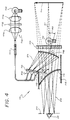
- the present invention is embodied in an optical display system, generally indicated by the numerous 10, which is mounted in the dashboard 12 of an automobile behind the steering wheel 14 and which produces a 3-D image 16 (FIG. 3) of a primary instrument cluster, including warning indicators, that can be viewed from an eye motion box 20 at the driver's location when the driver 22 looks down and scans across the dashboard panel region 24 in the manner illustrated schematically by the light rays 26.
- the system 10 embodying features of the present invention is sufficiently lightweight and compact (e.g. , typically about 10"W X 6"H X 8"D and weighing about 2-3 Kg.) to be packaged into the tight space which is available in the dashboard panel region 24.
- a typical 3-D instrument display image 16 produced by the display system 10 is similar in format to a conventional two-dimensional direct view instrument display and includes, for example a speedometer 32, a tachometer 34, an oil pressure warning indicator 36, an engine temperature warning indicator 38, a fuel level warning indicator 40, and a battery charge warning indicator 42, arranged in cluster fashion.
- the speedometer 32 and the tachometer 34 appear in a color (e.g. , green) which is different from the color (e.g. , red) of the warning indicators 36-42.
- the speedometer 32 and tachometer 34 appear in a forward focal plane 46, thus creating a 3-D effect.
- the driver 22 momentarily redirects his eyes from the view of the road which he sees through the windshield 48 (FIG. 1) to the view of the instrument image 16 which he sees in the direction of the dashboard panel region 24.
- the instrument image 16 illustrated in FIG. 3 shows the warning indicators 36-42 arranged off to the sides of the other instruments 32 and 34 in a manner which produces complementary images suitable for simultaneous display.
- the non-planar effect and the differing coloration is used to create a distinctive and highly stylistic appearance which gives the instrument cluster a "high-tech" look.
- the warning indicators which appear in the forward focal plane are made oversized and placed directly in front of the instruments which appear in the rearward focal plane. The indicators are then selectively activated and deactivated as needed, with the activated indicators overriding the rest of the image display to provide greater visual emphasis.
- This type of superimposed image arrangement also tends to reduce the overall field-of-view of the instrument display, thereby permitting a decrease in the package size and the optical complexity of the display system 10.
- the optical display system 10 creates a virtual image 50 (FIG. 4) of the instruments displayed in the rearward focal plane 44 at a viewing distance which is substantially greater than the actual optical path length between the eyes of the driver 22 and the physical location of the system 10.
- This enhances instrument readability, minimizes driver eye strain, and reduces eye focus problems when the driver 22 transitions between watching the road ahead and glancing at these instruments 32 and 34.
- the improvement is particularly significant for older persons who may have diminished eye focusing capability and for persons who are far sighted or wear bifocals and must pull their head back or tilt their head up to get a clear view of close objects.
- the system 10 improves display visibility and provides a high contrast, sharp and pleasing instrument presentation against typical ambient background levels. This arrangement is simple in structure and design and can be mass-produced at a reasonable cost.
- the preferred display system 10 includes a miniaturized quasi-monochromatic image source 54 which produces an object scene display of the desired rearward focal plane instruments 32 and 34, an illumination system 56 which illuminates the image source 54, and an optical imaging element, such as an off-axis aspheric narrow-band reflecting mirror 58 with power, which deviates the quasi-monochromatic light 59 from the image source 54 into the driver's eye motion box 20 and focuses the light to produce a quasi-monochromatic magnified virtual image 50 of the instruments displayed by the source 54 at a considerable distance ( e.g. , about one foot or more) beyond the dashboard panel 24 and a considerable distance ( e.g.
- Optical power achieves the desired eye-to-image distance notwithstanding vehicle design constraints which may limit the location of the image source 54 and the other optical components in the system 10 and which may limit the length of the optical path within the system 10.
- the field-of-view of the virtual image display 10 can be reduced relative to the angular subtense of a conventional instrument assembly 28 without substantially degrading the perceived visibility and readability of the instrument display.
- the display 10 embodying features of the present invention can be more easily packaged into the limited space available in the dashboard 12 and can free up space in the dashboard 12 for other uses.
- a virtual image display system 10 with a field-of-view of about 12°H X 3°V visible over an eye motion box 20 sufficient to accommodate most of the driver population ( e.g. , about 8"H X 4"V unvignetted) would provide a virtual image 50 of suitable size for automobile instruments.
- the full field-of-view can be shown within the desired eye motion box 20 with no obstructions or secondary folds in the path.
- the single reflecting surface 58 is used as in the entire optical imaging system, chromatic aberrations are substantially reduced or eliminated and the system 10 provides a particularly sharp color image.
- the aspheric nature of the narrow-band reflecting mirror 58 allows greater degrees of freedom in the design of the optical system and thus facilitates the task of providing a system 10 which has the image quality and physical characteristics desired for an automobile instrument display.
- the shape of the aspheric reflecting surface is computer-optimized to minimize aberrations, to reduce vertical disparity and field curvature, and to enhance system compactness by minimizing the radius of curvature of the mirror 58 and shortening the optical path length between the mirror 58 and the image source 54, all with a relatively non-complex optical design.
- a non-pupil forming optical system uses a lens group, or in the case of the instrument display system 10, the aspheric reflecting mirror 58 to magnify the image source 54 and produce a virtual image 50 at some distance from the driver 22.
- the virtual image 50 can be viewed optimally within a cone subtended by the mirror 58, but as the driver's eye 22 moves out of the optimal viewing cone, part of the image 50 begins to vignette ( i.e. , disappear). The further the driver 22 moves out of the central cone, the less of the image 50 he can see until eventually all of the image becomes vignetted.
- the optimal viewing region would be more confined and the virtual image would be completely vignetted when the driver's eyes moved out of the exit pupil.
- this added performance would come at the expense of additional optical elements (in the form of relay optics) and path length.
- the advantage of the non-pupil forming system resides in its relative simplicity.
- the overall length of the system is generally shorter than that of the pupil forming system which requires extra length to accommodate the additional relay optics.
- Any advantages offered by a pupil forming system in terms of aberration correction and distortion control are not essential in a look-down display such as the system 10, because the imagery in such a display is not being overplayed with a view of the real world. Greater levels of distortion and lower accuracy thus can be tolerated for acceptable performance.
- the desired levels of vertical disparity are well within the reach of a non-pupil forming system.
- packaging size is a constraint, as is the case with a system intended for use in the interior of an automobile, it is advantageous to place the optical system as close to the viewer as possible to minimize the size of the optics.
- a typical mirror 58 for a 12° field-of-view display would have a reflecting region about 8.5" wide.
- the reflecting region on the mirror 58 would be about 14.8 inches wide, which is about the same size as the conventional instrument assembly 28.
- the reflecting region of the aspheric mirror 58 is about 9.0"W X 5.0"H.
- the center 57 of the aspheric mirror 58 is located about 30" from the eye motion box 20 and about 5.6" from the face plane 60 of the image source 54 as measured along the line-of-sight axis (represented in FIG. 4 by the central light ray 61).
- the mirror 58 is oriented at an off-axis angle 62 of about 14.4° and the face plane 60 of the image source 54 is oriented at an angle 63 of about 78° with respect to the line-of-sight axis 61.
- the aspheric mirror 58 is a narrow-band reflective optical element.
- the aspheric mirror 58 is formed by a vapor deposition process of the type described, for example, in U.S. Patent No. 4,545,646, entitled “Process For Forming A Graded Index Optical Material and Structures Formed Thereby,” issued to Mao-Jin Chern et al, the entire disclosure of which is incorporated herein by reference.
- the narrow-band coating on the aspheric substrate reflects strongly the monochromatic color images from the image source, yet transmits other color images generated from the panel 120 in Fig. 4.
- the aspheric mirror is a narrow-band diffraction optical element which is generated using known methods of optical holography.
- a holographic mirror provides a number of advantages including, for example, a relatively high level of optical efficiency in reflecting light from the image source 54 to the eye motion box 20.
- a suitable holographic mirror 58 would include an aspheric reflection hologram optically recorded in a layer of photosensitive gelatin which is embedded in a spherical glass substrate.
- Narrow-band holographic mirrors for display system and methods for making the same are described, for example, in U.S. Patent No. 3,940,204, entitled "Optical Display Systems Utilizing Holographic Lenses", issued to Roger J. Withrington, the entire disclosure of which is incorporated herein by reference.
- the preferred embodiment of the invention utilizes a passive image source 54 which displays the desired rearward focal plane instruments 32 and 34 at the desired brightness and contrast, which is packaged into the available area in the dashboard 12, which provides the desired resolution and color, and that has input power requirements that are compatible with the electrical system of an automobile, all at a relatively low cost.
- the packaging and cost features are enhanced, in part, by taking advantage of optical power in the display system 10.
- Optical power allows the image source 54 to be miniaturized, i.e. , made smaller than the size of the desired instrument display to be seen in the virtual image 50.
- Liquid crystal displays are used in numerous consumer and industrial applications and are particularly desirable for use in automotive displays. They have a relatively thin panel, a high resolution due to the stroke quality of the segments, a high reliability, a low cost, and a low power consumption.
- the thickness of an LCD panel is about 0.25" for relatively large panels ( e.g. , 5" X 6").
- the low drive voltage typically in the range of about 2-10 volts, is also a desirable feature.
- LCDs have an operating and storage temperature range of about -40°C to +85°C, but because switching speeds tend to slow down at low temperatures, it may be desirable to add heater circuitry (not shown) to an LCD image source so that the display can continue to operate properly in cold weather within seconds of starting the automobile.
- Segmented LCD panels are particularly desirable for use in the image source 54 because they can be configured with bar graphics 66 (FIG. 3) which provide a conventional-looking instrument format.
- a segmented LCD modulates light from a stationary illumination source in order to create what appears to be a moving image (e.g. , a sliding indicator moving along a bar graph).
- a typical segmented LCD panel 70 of the twisted neumatic variety which is useful in the image source 54 includes an active liquid crystal layer 72 retained in a seal 74 between a pair of substrates 76 and 78.
- a pattern of spaced electrodes 80 are disposed along opposed surfaces 82 and 84 of the layer which have been chemically or physically treated to align the liquid crystal molecules.
- the electrodes 80 are selectively actuated to produce image pixels in a manner well known in the art. This entire structure is sandwiched between a pair of polarizers 86 and 88.
- the quasi-monochromatic image light used with the narrow-band mirror 58 is generated by appropriate color filters 90 which are laminated behind a diffusing screen 92 adhered to the rearward polarizer 88 or, in an alternative embodiment (not shown), are laminated between the polarizer 88 and the diffusing screen 92.
- Suitable color filters include dielectric filters and pigmented transparent filters. When used with the preferred holographic diffusion screen 92 discussed below, the color filters 90 are selected to pass the colors which are diffracted by the diffusing screen 92.
- a multi-color LCD image source for use with alternative embodiments of the invention discussed below includes color filters 90 which provide a collection of differently colored areas.
- image sources useful in the display system 10 include vacuum fluorescent displays, PLZT displays, miniature electro-mechanical dials, and hybrid combinations of mechanical dials and electro-optics sources.
- Dot matrix displays LCD-type or VF-type are particularly useful image sources where a reconfigurable image is desired.
- An alternative embodiment of the invention which provides reduced aberrations or a wider field-of-view in a curved image surface (not shown) and a field lens/prism (not shown) positioned in front of the curved surface.
- the shape of the image source 54 as seen in the virtual image 50 will be distorted.
- a geometry correction is introduced into the system to compensate for this distortion and to produce a virtual image 50 which, as seen by the driver 22, is geometrically correct.
- the distortion normally is compensated by the design of the image source 54.
- the graphic pattern design of the image source 54 is pre-distorted to incorporate the geometry correction.
- the correction is built into the design by purposely distorting the artwork and the segment pattern in accordance with a distortion curve which is shaped to counterbalance the distortion in the off-axis configuration. Since the segmented LCD layout is custom configured, the artwork used to make the display can be pre-distorted with little or no increase in production cost and with little or no degradation of image quality.
- FIG. 6 A distortion curve for the particular aspheric surface described above is illustrated in FIG. 6.
- the desired rectilinear virtual image 50 is presented by a rectangle 94 having dimensions of about 2.364"W X 0.699"H.
- the face of the LCD image source 54 is represented by a curvilinear grid pattern 96 which is disposed within the rectangle 94 about the center point 98.
- a passive (i.e. , non light emitting) image source 54 such as the segmented LCD panel 70
- illumination is provided by an external illumination system 56.
- the display should be made as transmissive as possible and yet maintain uniform high brightness and uniform contrast over the entire eye motion box 20.
- a holographic diffuser diffracts rather than scatters the light. All of the diffused illumination can be directed uniformally into an entrance pupil of the optical system and the diffraction angle can be readily adjusted to fit the optical configuration, thus providing high uniformity and high gain. With the eyellipse and eye-to-panel viewing distance encountered in the typical automobile environment, a hologram diffusing screen disposed between the illumination system 56 and the image source 54 diffuses the illumination light and provides a substantial improvement in display brightness.
- the diffusing screen element 92 adhered to the LCD panel 70 be a transmission hologram diffusing screen and, more particularly, be a directional diffusing screen generally of the type described in U.S. Patent No. 4,372,639, entitled “Directional Diffusing Screen", issued to Kenneth C. Johnson, the entire disclosure of which is incorporated herein by reference.
- the hologram is recorded so that the exit aperture properties of the transmission hologram thus direct the diffused light from the LCD panel 70 into the mirror aperture in a uniform and efficient manner.
- the virtual image 50 is provided with uniform high brightness and uniform contrast over the entire field-of-view when viewed from within the desired eye motion box 20.
- An alternative diffusing screen which is particularly useful in the display system 10 is the aspheric lenticular screen made by Protolyte.
- the lenticular screen has some of the desirable optical properties of a holographic diffusing screen but it is less sensitive to the wavelength and angle of incidence of the incoming light. Image source tilt can be substantially reduced or eliminated when the lenticular screen is used.
- the directional properties of the holographic diffusing screen 92 have the advantage of minimizing the visual impact of any aberrations, such as vertical disparity, residual distortion, horizontal focus and image motion, which may be present near the edge of the viewing area.
- any aberrations such as vertical disparity, residual distortion, horizontal focus and image motion, which may be present near the edge of the viewing area.
- the screen 92 reduces the intensity of the light at the edges of the viewing area in a desired manner and thus makes any aberrations there more tolerable to the driver 22.
- the non-pupil forming system can be made to achieve some of the desirable optical properties of a pupil forming system without the inherent limitations of such a system.
- a suitable technique for making the transmission hologram diffusing screen 92 includes a plurality of holograms which are recorded at different wavelengths and respectively located such that the screen 92 is made responsive to different colors in different areas.
- the illumination system 56 illuminates the image source 54 in a manner which provides the desired brightness, color balance, and uniformity.
- a fiber optic bundle 100 is used to pipe illumination to the LCD panel 70 from a remotely located lamp 102.
- the remote location is selected so that the lamp 102 is conveniently accessible for service or replacement in the case of lamp failure.
- the remote location also reduces the heat build-up in the region occupied by the image source 54.
- the lamp is mounted adjacent a rearward open end 103 of the dashboard 12.
- the light from the lamp 102 is collected and focused into the aperture of the fiber optic bundle 100 by an appropriate collimating aspheric lens 104 and an appropriate condensing aspheric lens 106.
- a filter 108 between the lenses 104 and 106 filters out light in the infrared wavelengths to facilitate the use of plastic fiber optics which have relatively low heat tolerance.
- the wattage of the lamp 102 is selected to take account of light loss and reduced light intensity which may occur when the illumination passes through the fiber optic bundle 100 and the collimating and condensing optics 104 and 106.
- a particularly inexpensive and durable lamp 102 which is useful in the illumination system 56 is an incandescent lamp.
- a lamp 102 with a small filament size in order to increase the collection efficiency into the optical fiber 100.
- An example of such an incandescent lamp is the lamp #1874.
- the nominal design voltage of that lamp is about 3.7 volts and the nominal power consumption is about 10 watts.
- the lamp has a high luminous output and is therefore particularly well suited for a fiber bundle configuration.
- the lamp should produce an image brightness which is sufficient for an effective display presentation at night or in the high ambient light conditions of daytime.
- the exit aperture of the fiber optic bundle 100 is arranged to provide a backlit lighting scheme. Backlighting substantially eliminates the shadow effect which can be caused by the gap distance between the active liquid crystal layer 72 and the diffusing element 92 adhered to the LCD panel 70.
- the fiber optic bundle 100 extends from the incandescent lamp 102 and preferably terminates behind the LCD panel assembly 70 in a plurality of spaced-apart ends 110.
- the light from each of the ends 110 is directed through the panel 70 where it is diffused by the transmission hologram diffusing element 92 and filtered by the color filter 90.
- a high degree of illumination uniformity is achieved across the panel 70 within a closer illumination distance.
- the desired uniformity can be achieved with the endings 100 only about 1" from the panel 70.
- the primary source of unwanted ambient light in the display system 10 is the diffuse reflection of the outside ambient (i.e. , the sun and sky) off of the driver 22 and the interior of the automobile.
- the display system housing Through proper design of the display system housing, direct illumination by outside ambient can be substantially blocked.
- the preferred embodiment of the invention includes a display system 10 which is enclosed at the front by a curved, plastic sheet, glare shield 112 oriented at an angle of about 45° with respect to the line-of-sight axis.
- the shield 112 traps firs surface reflections off of the sides of the display housing and off the glare shield 112 itself.
- the shield 112 is mounted in the plane between the bottom of the image source 54 and the bottom of the mirror 58 to prevent foreign objects from falling into the optical system.
- the curvature and angel of the shield 112 are selected so that any ambient reflection from the eye box area 20 is directed away from the image source 54 and into a light trap (e.g. , a black surface 114 on the top of a lower projecting portion 116 of the dashboard 12), to preserve the high contrast of the virtual image 16.
- a light trap e.g. , a black surface 114 on the top of a lower projecting portion 116 of the dashboard 12
- the surface quality of the glare shield 112 is made high so that residual striae or defects therein will have minimal impact on the optical performance of the system 10.
- a suitable glare shield 112 is an optically clear plate or a neutral density filter.
- the shield 112 is preferably made of a contrast enhancement filter material such as the Didymium glass filter developed for sue as a contrast enhancement faceplate for a color CRT display.
- First surface reflections off of the image source 54 are substantially minimized or eliminated by tilting the face of the source 54 towards the interior of the display housing or by applying a broadband anti-reflection coating thereto.
- Light baffles (not shown) and light absorbing paint on the interior surfaces of the display housing also may be used to further reduce ambient reflections.
- a holographic reflecting mirror 58 can also improve the image contrast by reducing the amount of unwanted ambient light with contributes to the general background brightness of the image source 54.
- the angular and wavelength sensitive properties of a single narrow-band hologram will typically permit only about 10% - 20% of the ambient illumination to reflect off the mirror 58 and enter the region around the image source 54. The remaining 80-90% of the ambient light would transmit through the mirror and be absorbed by black surfaces 118 in the interior of the display housing.
- the resulting improvement in contrast would promote a sharp and readable virtual image 50 even under conditions of high ambient light and would permit the use of a lower wattage lamp 102 in the illumination system 56.
- the images for the warning indicators 36-42 or other instruments displayed in the forward focal plane 46 are produced by a secondary image source 120 positioned directly behind the reflecting mirror 58 in the driver's line-of-sight 61.
- This secondary image source 120 is illuminated by its own secondary light source 122 and produces an image in front of the virtual image 50 near the location of the dashboard panel 24. Both the secondary image source 120 and the secondary light source are shown schematically in FIGS. 1, 2 and 4.
- the narrow-band reflecting mirror 58 will reflect the light produced by the monochromatic image source 54, but it will substantially transmit light of different colors which emanates from the secondary image source 120. For example, if the reflecting mirror 58 is tuned to a narrow-band green, then a secondary image source 120 with multi-color capability could transmit blue, yellow and/or red images through the reflecting mirror 58. The driver would see a display of the images produced by the secondary image source 120 simultaneously with the green virtual image 50 produced by the monochromatic image source 54, but he would see them in different focal planes, thus creating the perception of a 3-D display.
- the narrow-band character of the reflecting mirror 58 would help preserve the separation of the forward and rearward planes 44 and 46 of the 3-D image because it would substantially preclude the monochromatic image source 54 from illuminating the secondary image source 120.
- the secondary image source 120 is a backlit panel display such as vacuum fluorescent panel or a liquid crystal display.
- the panel display can be monochromatic or multi-colored and can produce a variety of different instrument images, as desired and as described previously with reference to the discussion of the 3-D image 16 shown in FIG. 3.
- the secondary light source 122 can be a local lamp or it can be a remotely positioned illumination system similar to the one used for illuminating the monochromatic LCD panel 70.
- an alternative embodiment of the present invention resides in an optical display system 125 in which the single aspheric narrow-band reflecting mirror is split into a plurality of aspheric narrow-band reflecting mirrors 130, 132 and 134, each tuned to reflect a different wavelength bandwidth.
- the mirror 130 nearest the image source 54' could be tuned to reflect red
- the mirror 134 farthest from the image source could be tuned to reflect blue
- the mirror 132 in between could be tuned to reflect green.
- each mirror 130, 132 and 134 When these mirror 130, 132 and 134 are exposed to light from a multi-color embodiment of the image source 54', the various color bands in the image will be separately reflected by their corresponding mirror and transmitted through the other mirror. Each mirror 130, 132 and 134 will thus produce its own magnified virtual image 136, 138 and 140 in its own particular monochromatic color at a location which is well beyond the dashboard panel 24.
- the curvatures of the various mirrors 130, 132 and 134 are made different from each other so that the differently colored virtual image planes 136, 138 and 140 will be spatially separated and give the illusion of a 3-D image located remote from the driver's eyes 22.
- the near range mirror 130 has a base curve radius of about 14
- the middle range mirror 134 has a base curve radius of about 18".
- the curvature refers to the holographically recorded radius of the fringe pattern.
- the preferred embodiment of the plural mirror display system 125 utilizes an arrangement in which the various reflecting mirrors 130, 132 and 134 are stacked together into an integral mirror assembly 142.
- a layer of photosensitive gelatin 144 used for recording the middle range mirror 132 is sandwiched between appropriately curved surfaces 146 and 148 of a pair of spherical glass or plastic substrates 150 and 152.
- the layers of gelatin 154 and 156 used for recording the near range and far range mirrors 130 and 134, respectfully, are applied to the opposed and appropriately curved surfaces 158 and 160 of those same substrates 150 and 152.
- the various reflecting mirrors 130, 132 and 134 are all recorded in a single layer of photosensitive gelatin by exposing that layer to plural holographic exposures.
- the various reflecting mirrors 130, 132 and 134 are made of photo-chemical vapor deposition coatings with graded index structure for narrow band reflection.
- Yet another embodiment of the present invention provides a display system 170 which is capable of producing a substantially 3-D image at a distance well beyond the dashboard panel 24.
- the system 170 utilizes an image source 172 which includes a plurality of non-planar segments 174, 176 and 178, each of which is similar in structure and arrangement to the image source 54 uses in the display system 10 described with reference to FIG. 4.
- Each image source can be multi-color.
- the broad band reflecting mirror 58'' produces a magnified virtual image 180 which tracks the spatial configuration of the segmented image source 172.
- the virtual image 180 has a substantially corresponding arrangement of spatially separated, non-planar image segments 182, 184 and 186.
- the present invention provides an inexpensive and mass-producible display system with optical power which is compatible with the styling and limited space available in the interior of an automobile and which creates a dramatic and highly stylistic, high contrast, sharp and pleasing, multi-color or monochromatic 3-D image of an automotive instrument cluster, at least a portion of the image being located at a viewing distance substantially beyond the face of the dashboard in order to enhance instrument readability and minimize driver eye strain.
Landscapes
- Engineering & Computer Science (AREA)
- Mechanical Engineering (AREA)
- Physics & Mathematics (AREA)
- General Physics & Mathematics (AREA)
- Chemical & Material Sciences (AREA)
- Combustion & Propulsion (AREA)
- Transportation (AREA)
- Optics & Photonics (AREA)
- Instrument Panels (AREA)
Applications Claiming Priority (2)
| Application Number | Priority Date | Filing Date | Title |
|---|---|---|---|
| US130066 | 1993-09-30 | ||
| US08/130,066 US5440428A (en) | 1993-09-30 | 1993-09-30 | Automotive instrument 3-D virtual image display |
Publications (2)
| Publication Number | Publication Date |
|---|---|
| EP0646823A2 true EP0646823A2 (de) | 1995-04-05 |
| EP0646823A3 EP0646823A3 (de) | 1996-06-12 |
Family
ID=22442898
Family Applications (1)
| Application Number | Title | Priority Date | Filing Date |
|---|---|---|---|
| EP94115353A Withdrawn EP0646823A3 (de) | 1993-09-30 | 1994-09-29 | Virtuell abbildende 3 D Anzeige für Autos. |
Country Status (5)
| Country | Link |
|---|---|
| US (1) | US5440428A (de) |
| EP (1) | EP0646823A3 (de) |
| JP (1) | JPH07186778A (de) |
| KR (1) | KR950009520A (de) |
| CA (1) | CA2132999A1 (de) |
Cited By (12)
| Publication number | Priority date | Publication date | Assignee | Title |
|---|---|---|---|---|
| WO1998057215A1 (es) * | 1997-06-09 | 1998-12-17 | Dominguez Montes Juan | Adaptador optico acoplable a cualquier pantalla difusora perteneciente a un unico dispositivo de reproduccion convencional, capaz de producir efectos tridimensionales |
| ES2152905A1 (es) * | 1997-06-09 | 2001-02-01 | Dominguez Montes Juan | Adaptador optico acoplable a cualquier pantalla difusora perteneciente a un unico dispositivo de reproduccion convencional, capaz de producir efectos tridimensionales. |
| US6741223B2 (en) | 2001-06-11 | 2004-05-25 | Honda Giken Kogyo Kabushiki Kaisha | Display device for vehicle |
| EP1104716A3 (de) * | 1999-12-01 | 2005-09-07 | Volkswagen Aktiengesellschaft | Kombi-Instrument für Kraftfahrzeug |
| WO2006041876A1 (en) * | 2004-10-06 | 2006-04-20 | Johnson Controls Technology Company | Instrument cluster with translucent or transparent sheet |
| DE102004054768A1 (de) * | 2004-11-12 | 2006-05-18 | Volkswagen Ag | Displayvorrichtung |
| DE102005034096A1 (de) * | 2005-07-21 | 2007-01-25 | Volkswagen Ag | Kombiinstrument für ein Kraftfahrzeug |
| WO2008087013A1 (de) * | 2007-01-18 | 2008-07-24 | Johnson Controls Gmbh | Anzeigeinstrument und verfahren zum betrieb eines anzeigeinstruments |
| FR3051406A1 (fr) * | 2016-05-20 | 2017-11-24 | Peugeot Citroen Automobiles Sa | Combine d’instruments pour planche de bord de vehicule automobile dote de moyens de reflexion optique grossissants. |
| WO2018154032A1 (de) * | 2017-02-27 | 2018-08-30 | Audi Ag | Kraftfahrzeug mit einer anzeigeanordnung und verfahren zum betreiben einer anzeigeanordnung eines kraftfahrzeugs |
| WO2018219794A1 (de) * | 2017-05-31 | 2018-12-06 | Audi Ag | Anzeigesystem |
| DE102021128187A1 (de) | 2021-10-28 | 2023-05-04 | Bayerische Motoren Werke Aktiengesellschaft | Nicht-spiegelndes Beifahrerentertainment |
Families Citing this family (178)
| Publication number | Priority date | Publication date | Assignee | Title |
|---|---|---|---|---|
| US5864428A (en) * | 1992-01-13 | 1999-01-26 | Hesline; Raymond | Polarizing device |
| US5670935A (en) * | 1993-02-26 | 1997-09-23 | Donnelly Corporation | Rearview vision system for vehicle including panoramic view |
| US5877897A (en) | 1993-02-26 | 1999-03-02 | Donnelly Corporation | Automatic rearview mirror, vehicle lighting control and vehicle interior monitoring system using a photosensor array |
| US6822563B2 (en) | 1997-09-22 | 2004-11-23 | Donnelly Corporation | Vehicle imaging system with accessory control |
| US6891563B2 (en) | 1996-05-22 | 2005-05-10 | Donnelly Corporation | Vehicular vision system |
| US5629996A (en) * | 1995-11-29 | 1997-05-13 | Physical Optics Corporation | Universal remote lighting system with nonimaging total internal reflection beam transformer |
| US5821867A (en) * | 1995-12-08 | 1998-10-13 | Ford Motor Company | Transreflective instrument display |
| US5625736A (en) * | 1996-01-11 | 1997-04-29 | Associated Universities, Inc. | Black optic display |
| MY121665A (en) * | 1996-02-29 | 2006-02-28 | Sumitomo Chemical Co | Insect controller |
| EP0886802B1 (de) | 1996-03-15 | 2001-11-21 | Retinal Display Cayman Ltd. | Verfahren und vorrichtung zur betrachtung eines bildes |
| US7655894B2 (en) | 1996-03-25 | 2010-02-02 | Donnelly Corporation | Vehicular image sensing system |
| US6009355A (en) | 1997-01-28 | 1999-12-28 | American Calcar Inc. | Multimedia information and control system for automobiles |
| US6148261A (en) | 1997-06-20 | 2000-11-14 | American Calcar, Inc. | Personal communication system to send and receive voice data positioning information |
| US6275231B1 (en) | 1997-08-01 | 2001-08-14 | American Calcar Inc. | Centralized control and management system for automobiles |
| US5986792A (en) * | 1998-02-03 | 1999-11-16 | Farlight Corporation | Lighting system sequencer and method |
| JPH11305743A (ja) * | 1998-04-23 | 1999-11-05 | Semiconductor Energy Lab Co Ltd | 液晶表示装置 |
| WO2000007066A1 (en) | 1998-07-29 | 2000-02-10 | Digilens, Inc. | In-line infinity display system employing one or more switchable holographic optical elements |
| EP1114340A1 (de) * | 1998-09-14 | 2001-07-11 | Digilens Inc. | Holographisches beleuchtungssystem und holographisches projektionssystem |
| WO2000023835A1 (en) | 1998-10-16 | 2000-04-27 | Digilens, Inc. | Holographic technique for illumination of image displays using ambient illumination |
| US6094283A (en) * | 1998-10-16 | 2000-07-25 | Digilens, Inc. | Holographic display with switchable aspect ratio |
| WO2000024204A1 (en) | 1998-10-16 | 2000-04-27 | Digilens, Inc. | Method and system for display resolution multiplication |
| US6115151A (en) * | 1998-12-30 | 2000-09-05 | Digilens, Inc. | Method for producing a multi-layer holographic device |
| US6678078B1 (en) | 1999-01-07 | 2004-01-13 | Digilens, Inc. | Optical filter employing holographic optical elements and image generating system incorporating the optical filter |
| EP1067502B1 (de) * | 1999-01-25 | 2010-05-05 | Nippon Seiki Co., Ltd. | Anzeige |
| US6507419B1 (en) | 1999-03-23 | 2003-01-14 | Digilens, Inc. | Illumination system using optical feedback |
| US6504629B1 (en) | 1999-03-23 | 2003-01-07 | Digilens, Inc. | Method and apparatus for illuminating a display |
| US6178018B1 (en) | 1999-06-25 | 2001-01-23 | International Business Machines Corporation | Process and method employing dynamic holographic display medium |
| AU6400300A (en) | 1999-08-04 | 2001-03-05 | Digilens Inc. | Apparatus for producing a three-dimensional image |
| US6323970B1 (en) | 1999-09-29 | 2001-11-27 | Digilents, Inc. | Method of producing switchable holograms |
| JP4245750B2 (ja) * | 1999-10-15 | 2009-04-02 | オリンパス株式会社 | 立体観察装置 |
| US6446869B1 (en) * | 2000-02-10 | 2002-09-10 | Ncr Corporation | Ambient light blocking apparatus for a produce recognition system |
| US7187947B1 (en) | 2000-03-28 | 2007-03-06 | Affinity Labs, Llc | System and method for communicating selected information to an electronic device |
| US6353422B1 (en) * | 2000-03-31 | 2002-03-05 | Stephen G. Perlman | Virtual display system and method |
| US6396408B2 (en) | 2000-03-31 | 2002-05-28 | Donnelly Corporation | Digital electrochromic circuit with a vehicle network |
| US8990367B2 (en) * | 2006-09-29 | 2015-03-24 | Dell Products L.P. | Consistent binding of shared storage across clustered servers |
| EP1328420A4 (de) | 2000-09-21 | 2009-03-04 | American Calcar Inc | Verfahren zum wirksamen und sicheren bedienen eines fahrzeugs |
| US6424437B1 (en) | 2000-10-10 | 2002-07-23 | Digilens, Inc. | Projection display employing switchable holographic optical elements |
| CA2463922C (en) | 2001-06-27 | 2013-07-16 | 4 Media, Inc. | Improved media delivery platform |
| US7697027B2 (en) | 2001-07-31 | 2010-04-13 | Donnelly Corporation | Vehicular video system |
| US6882287B2 (en) | 2001-07-31 | 2005-04-19 | Donnelly Corporation | Automotive lane change aid |
| AU2003225228A1 (en) | 2002-05-03 | 2003-11-17 | Donnelly Corporation | Object detection system for vehicle |
| WO2003100517A2 (en) * | 2002-05-22 | 2003-12-04 | Chelix Technologies Corp. | Real image configuration for a high efficiency heads-up display (hud) using a polarizing mirror and a polarization preserving screen |
| AU2003294581A1 (en) * | 2002-12-06 | 2004-06-30 | Cross Match Technologies, Inc. | Systems and methods for capturing print information using a coordinate conversion method and for generating a preview display |
| US7321671B2 (en) * | 2002-12-06 | 2008-01-22 | Cross Match Technologies, Inc. | System and method for generating a preview display in a print capturing system using a non-planar prism |
| US9818136B1 (en) | 2003-02-05 | 2017-11-14 | Steven M. Hoffberg | System and method for determining contingent relevance |
| EP1462297A3 (de) * | 2003-03-26 | 2007-05-09 | Calsonic Kansei Corporation | Informationsanzeigegerät für Fahrzeuge |
| US7081951B2 (en) * | 2003-10-09 | 2006-07-25 | Cross Match Technologies, Inc. | Palm print scanner and methods |
| US7308341B2 (en) | 2003-10-14 | 2007-12-11 | Donnelly Corporation | Vehicle communication system |
| US10277290B2 (en) | 2004-04-02 | 2019-04-30 | Rearden, Llc | Systems and methods to exploit areas of coherence in wireless systems |
| US8654815B1 (en) | 2004-04-02 | 2014-02-18 | Rearden, Llc | System and method for distributed antenna wireless communications |
| US9819403B2 (en) | 2004-04-02 | 2017-11-14 | Rearden, Llc | System and method for managing handoff of a client between different distributed-input-distributed-output (DIDO) networks based on detected velocity of the client |
| US10425134B2 (en) | 2004-04-02 | 2019-09-24 | Rearden, Llc | System and methods for planned evolution and obsolescence of multiuser spectrum |
| US9826537B2 (en) | 2004-04-02 | 2017-11-21 | Rearden, Llc | System and method for managing inter-cluster handoff of clients which traverse multiple DIDO clusters |
| US7526103B2 (en) | 2004-04-15 | 2009-04-28 | Donnelly Corporation | Imaging system for vehicle |
| JP4492208B2 (ja) * | 2004-05-14 | 2010-06-30 | パナソニック株式会社 | 三次元画像再生装置 |
| US7881496B2 (en) | 2004-09-30 | 2011-02-01 | Donnelly Corporation | Vision system for vehicle |
| EP1647867A1 (de) * | 2004-10-11 | 2006-04-19 | The Swatch Group Management Services AG | Vergrösserungsvorrichtung für Uhren |
| US20060092521A1 (en) * | 2004-10-28 | 2006-05-04 | Siemens Vdo Automotive Corporation | Three dimensional dial for vehicle |
| US7720580B2 (en) | 2004-12-23 | 2010-05-18 | Donnelly Corporation | Object detection system for vehicle |
| DE102005017313A1 (de) * | 2005-04-14 | 2006-10-19 | Volkswagen Ag | Verfahren zur Darstellung von Informationen in einem Verkehrsmittel und Kombiinstrument für ein Kraftfahrzeug |
| US8874477B2 (en) | 2005-10-04 | 2014-10-28 | Steven Mark Hoffberg | Multifactorial optimization system and method |
| WO2008024639A2 (en) | 2006-08-11 | 2008-02-28 | Donnelly Corporation | Automatic headlamp control system |
| US8013780B2 (en) | 2007-01-25 | 2011-09-06 | Magna Electronics Inc. | Radar sensing system for vehicle |
| US7914187B2 (en) | 2007-07-12 | 2011-03-29 | Magna Electronics Inc. | Automatic lighting system with adaptive alignment function |
| US8017898B2 (en) | 2007-08-17 | 2011-09-13 | Magna Electronics Inc. | Vehicular imaging system in an automatic headlamp control system |
| US8451107B2 (en) | 2007-09-11 | 2013-05-28 | Magna Electronics, Inc. | Imaging system for vehicle |
| WO2009046268A1 (en) | 2007-10-04 | 2009-04-09 | Magna Electronics | Combined rgb and ir imaging sensor |
| CN101911174B (zh) * | 2008-02-27 | 2013-06-26 | 夏普株式会社 | 液晶显示装置及液晶显示装置中的图像处理方法 |
| JP5146908B2 (ja) * | 2008-03-19 | 2013-02-20 | 日本精機株式会社 | ヘッドアップディスプレイ装置 |
| GB0808593D0 (en) * | 2008-05-13 | 2008-06-18 | Activ8 3D Ltd | Display apparatus |
| US20100020170A1 (en) | 2008-07-24 | 2010-01-28 | Higgins-Luthman Michael J | Vehicle Imaging System |
| JP5181939B2 (ja) * | 2008-09-03 | 2013-04-10 | アイシン・エィ・ダブリュ株式会社 | 車両用計器表示装置、車両用計器表示方法及びコンピュータプログラム |
| EP2401176B1 (de) | 2009-02-27 | 2019-05-08 | Magna Electronics | Fahrzeugalarmsystem |
| US8376595B2 (en) | 2009-05-15 | 2013-02-19 | Magna Electronics, Inc. | Automatic headlamp control |
| CN102481874B (zh) | 2009-07-27 | 2015-08-05 | 马格纳电子系统公司 | 停车辅助系统 |
| US9495876B2 (en) | 2009-07-27 | 2016-11-15 | Magna Electronics Inc. | Vehicular camera with on-board microcontroller |
| EP2473871B1 (de) | 2009-09-01 | 2015-03-11 | Magna Mirrors Of America, Inc. | Abbildungs- und anzeigesystem für fahrzeuge |
| US8890955B2 (en) | 2010-02-10 | 2014-11-18 | Magna Mirrors Of America, Inc. | Adaptable wireless vehicle vision system based on wireless communication error |
| US9117123B2 (en) | 2010-07-05 | 2015-08-25 | Magna Electronics Inc. | Vehicular rear view camera display system with lifecheck function |
| DE112011103834T8 (de) | 2010-11-19 | 2013-09-12 | Magna Electronics, Inc. | Spurhalteassistent und Spurzentrierung |
| WO2012075250A1 (en) | 2010-12-01 | 2012-06-07 | Magna Electronics Inc. | System and method of establishing a multi-camera image using pixel remapping |
| US9264672B2 (en) | 2010-12-22 | 2016-02-16 | Magna Mirrors Of America, Inc. | Vision display system for vehicle |
| US9085261B2 (en) | 2011-01-26 | 2015-07-21 | Magna Electronics Inc. | Rear vision system with trailer angle detection |
| US9194943B2 (en) | 2011-04-12 | 2015-11-24 | Magna Electronics Inc. | Step filter for estimating distance in a time-of-flight ranging system |
| US9357208B2 (en) | 2011-04-25 | 2016-05-31 | Magna Electronics Inc. | Method and system for dynamically calibrating vehicular cameras |
| WO2012145822A1 (en) | 2011-04-25 | 2012-11-01 | Magna International Inc. | Method and system for dynamically calibrating vehicular cameras |
| WO2012145819A1 (en) | 2011-04-25 | 2012-11-01 | Magna International Inc. | Image processing method for detecting objects using relative motion |
| US10793067B2 (en) | 2011-07-26 | 2020-10-06 | Magna Electronics Inc. | Imaging system for vehicle |
| US9491450B2 (en) | 2011-08-01 | 2016-11-08 | Magna Electronic Inc. | Vehicle camera alignment system |
| FR2979081A1 (fr) | 2011-08-18 | 2013-02-22 | Johnson Contr Automotive Elect | Dispositif d'affichage, notamment pour vehicule automobile |
| JP5310810B2 (ja) * | 2011-08-27 | 2013-10-09 | 株式会社デンソー | ヘッドアップディスプレイ装置 |
| JP5344069B2 (ja) * | 2011-08-29 | 2013-11-20 | 株式会社デンソー | ヘッドアップディスプレイ装置 |
| US20140218535A1 (en) | 2011-09-21 | 2014-08-07 | Magna Electronics Inc. | Vehicle vision system using image data transmission and power supply via a coaxial cable |
| US9681062B2 (en) | 2011-09-26 | 2017-06-13 | Magna Electronics Inc. | Vehicle camera image quality improvement in poor visibility conditions by contrast amplification |
| US9146898B2 (en) | 2011-10-27 | 2015-09-29 | Magna Electronics Inc. | Driver assist system with algorithm switching |
| US9491451B2 (en) | 2011-11-15 | 2016-11-08 | Magna Electronics Inc. | Calibration system and method for vehicular surround vision system |
| US10099614B2 (en) | 2011-11-28 | 2018-10-16 | Magna Electronics Inc. | Vision system for vehicle |
| WO2013086249A2 (en) | 2011-12-09 | 2013-06-13 | Magna Electronics, Inc. | Vehicle vision system with customized display |
| WO2013126715A2 (en) | 2012-02-22 | 2013-08-29 | Magna Electronics, Inc. | Vehicle camera system with image manipulation |
| US8694224B2 (en) | 2012-03-01 | 2014-04-08 | Magna Electronics Inc. | Vehicle yaw rate correction |
| US10609335B2 (en) | 2012-03-23 | 2020-03-31 | Magna Electronics Inc. | Vehicle vision system with accelerated object confirmation |
| WO2013158592A2 (en) | 2012-04-16 | 2013-10-24 | Magna Electronics, Inc. | Vehicle vision system with reduced image color data processing by use of dithering |
| US10089537B2 (en) | 2012-05-18 | 2018-10-02 | Magna Electronics Inc. | Vehicle vision system with front and rear camera integration |
| FR2990907B1 (fr) * | 2012-05-23 | 2015-03-20 | Continental Automotive France | Afficheur avec suppression de double image |
| CN103507639B (zh) * | 2012-06-27 | 2016-06-01 | 比亚迪股份有限公司 | 一种车载显示设备及具有该设备的车辆 |
| US9340227B2 (en) | 2012-08-14 | 2016-05-17 | Magna Electronics Inc. | Vehicle lane keep assist system |
| DE102013217430A1 (de) | 2012-09-04 | 2014-03-06 | Magna Electronics, Inc. | Fahrerassistenzsystem für ein Kraftfahrzeug |
| US9446713B2 (en) | 2012-09-26 | 2016-09-20 | Magna Electronics Inc. | Trailer angle detection system |
| US9558409B2 (en) | 2012-09-26 | 2017-01-31 | Magna Electronics Inc. | Vehicle vision system with trailer angle detection |
| US9723272B2 (en) | 2012-10-05 | 2017-08-01 | Magna Electronics Inc. | Multi-camera image stitching calibration system |
| US9743002B2 (en) | 2012-11-19 | 2017-08-22 | Magna Electronics Inc. | Vehicle vision system with enhanced display functions |
| US9090234B2 (en) | 2012-11-19 | 2015-07-28 | Magna Electronics Inc. | Braking control system for vehicle |
| US11189917B2 (en) | 2014-04-16 | 2021-11-30 | Rearden, Llc | Systems and methods for distributing radioheads |
| US10025994B2 (en) | 2012-12-04 | 2018-07-17 | Magna Electronics Inc. | Vehicle vision system utilizing corner detection |
| US9481301B2 (en) | 2012-12-05 | 2016-11-01 | Magna Electronics Inc. | Vehicle vision system utilizing camera synchronization |
| DE102012023941A1 (de) | 2012-12-06 | 2014-06-12 | GM Global Technology Operations LLC (n. d. Gesetzen des Staates Delaware) | Kraftfahrzeug-Cockpit mit einer Anzeigeneinheit und einem Schattenbereich |
| US20140191567A1 (en) * | 2013-01-08 | 2014-07-10 | Denso Corporation | Meter with projector for vehicle |
| US20140218529A1 (en) | 2013-02-04 | 2014-08-07 | Magna Electronics Inc. | Vehicle data recording system |
| US9092986B2 (en) | 2013-02-04 | 2015-07-28 | Magna Electronics Inc. | Vehicular vision system |
| US10179543B2 (en) | 2013-02-27 | 2019-01-15 | Magna Electronics Inc. | Multi-camera dynamic top view vision system |
| US9688200B2 (en) | 2013-03-04 | 2017-06-27 | Magna Electronics Inc. | Calibration system and method for multi-camera vision system |
| US9973246B2 (en) | 2013-03-12 | 2018-05-15 | Rearden, Llc | Systems and methods for exploiting inter-cell multiplexing gain in wireless cellular systems via distributed input distributed output technology |
| US9923657B2 (en) | 2013-03-12 | 2018-03-20 | Rearden, Llc | Systems and methods for exploiting inter-cell multiplexing gain in wireless cellular systems via distributed input distributed output technology |
| US10488535B2 (en) | 2013-03-12 | 2019-11-26 | Rearden, Llc | Apparatus and method for capturing still images and video using diffraction coded imaging techniques |
| JP5689910B2 (ja) * | 2013-03-12 | 2015-03-25 | 本田技研工業株式会社 | ヘッドアップディスプレイ装置 |
| US9164281B2 (en) | 2013-03-15 | 2015-10-20 | Honda Motor Co., Ltd. | Volumetric heads-up display with dynamic focal plane |
| US9378644B2 (en) | 2013-03-15 | 2016-06-28 | Honda Motor Co., Ltd. | System and method for warning a driver of a potential rear end collision |
| US10339711B2 (en) | 2013-03-15 | 2019-07-02 | Honda Motor Co., Ltd. | System and method for providing augmented reality based directions based on verbal and gestural cues |
| US10547358B2 (en) | 2013-03-15 | 2020-01-28 | Rearden, Llc | Systems and methods for radio frequency calibration exploiting channel reciprocity in distributed input distributed output wireless communications |
| US9251715B2 (en) | 2013-03-15 | 2016-02-02 | Honda Motor Co., Ltd. | Driver training system using heads-up display augmented reality graphics elements |
| US9393870B2 (en) | 2013-03-15 | 2016-07-19 | Honda Motor Co., Ltd. | Volumetric heads-up display with dynamic focal plane |
| US9747898B2 (en) | 2013-03-15 | 2017-08-29 | Honda Motor Co., Ltd. | Interpretation of ambiguous vehicle instructions |
| US10215583B2 (en) | 2013-03-15 | 2019-02-26 | Honda Motor Co., Ltd. | Multi-level navigation monitoring and control |
| US10027930B2 (en) | 2013-03-29 | 2018-07-17 | Magna Electronics Inc. | Spectral filtering for vehicular driver assistance systems |
| US9327693B2 (en) | 2013-04-10 | 2016-05-03 | Magna Electronics Inc. | Rear collision avoidance system for vehicle |
| JP5983667B2 (ja) * | 2013-04-11 | 2016-09-06 | 株式会社デンソー | 車両用表示装置 |
| US10232797B2 (en) | 2013-04-29 | 2019-03-19 | Magna Electronics Inc. | Rear vision system for vehicle with dual purpose signal lines |
| US9508014B2 (en) | 2013-05-06 | 2016-11-29 | Magna Electronics Inc. | Vehicular multi-camera vision system |
| US9205776B2 (en) | 2013-05-21 | 2015-12-08 | Magna Electronics Inc. | Vehicle vision system using kinematic model of vehicle motion |
| US9563951B2 (en) | 2013-05-21 | 2017-02-07 | Magna Electronics Inc. | Vehicle vision system with targetless camera calibration |
| US10567705B2 (en) | 2013-06-10 | 2020-02-18 | Magna Electronics Inc. | Coaxial cable with bidirectional data transmission |
| US9260095B2 (en) | 2013-06-19 | 2016-02-16 | Magna Electronics Inc. | Vehicle vision system with collision mitigation |
| US20140375476A1 (en) | 2013-06-24 | 2014-12-25 | Magna Electronics Inc. | Vehicle alert system |
| US9619716B2 (en) | 2013-08-12 | 2017-04-11 | Magna Electronics Inc. | Vehicle vision system with image classification |
| US10326969B2 (en) | 2013-08-12 | 2019-06-18 | Magna Electronics Inc. | Vehicle vision system with reduction of temporal noise in images |
| FR3011644B1 (fr) * | 2013-10-03 | 2016-01-01 | Commissariat Energie Atomique | Dispositif d'affichage en retroprojection |
| US9499139B2 (en) | 2013-12-05 | 2016-11-22 | Magna Electronics Inc. | Vehicle monitoring system |
| US9988047B2 (en) | 2013-12-12 | 2018-06-05 | Magna Electronics Inc. | Vehicle control system with traffic driving control |
| US10160382B2 (en) | 2014-02-04 | 2018-12-25 | Magna Electronics Inc. | Trailer backup assist system |
| JP6374676B2 (ja) * | 2014-03-10 | 2018-08-15 | 矢崎総業株式会社 | 車両用発光表示装置及び車両用表示システム |
| US9623878B2 (en) | 2014-04-02 | 2017-04-18 | Magna Electronics Inc. | Personalized driver assistance system for vehicle |
| US9487235B2 (en) | 2014-04-10 | 2016-11-08 | Magna Electronics Inc. | Vehicle control system with adaptive wheel angle correction |
| US10328932B2 (en) | 2014-06-02 | 2019-06-25 | Magna Electronics Inc. | Parking assist system with annotated map generation |
| KR20160024483A (ko) * | 2014-08-26 | 2016-03-07 | 현대모비스 주식회사 | 차량용 광학 구조 |
| US9547172B2 (en) | 2014-10-13 | 2017-01-17 | Ford Global Technologies, Llc | Vehicle image display |
| KR102232693B1 (ko) | 2014-10-17 | 2021-03-29 | 삼성디스플레이 주식회사 | 플렉서블 디스플레이 장치 |
| US9916660B2 (en) | 2015-01-16 | 2018-03-13 | Magna Electronics Inc. | Vehicle vision system with calibration algorithm |
| US10946799B2 (en) | 2015-04-21 | 2021-03-16 | Magna Electronics Inc. | Vehicle vision system with overlay calibration |
| US10819943B2 (en) | 2015-05-07 | 2020-10-27 | Magna Electronics Inc. | Vehicle vision system with incident recording function |
| US10214206B2 (en) | 2015-07-13 | 2019-02-26 | Magna Electronics Inc. | Parking assist system for vehicle |
| US10078789B2 (en) | 2015-07-17 | 2018-09-18 | Magna Electronics Inc. | Vehicle parking assist system with vision-based parking space detection |
| US10086870B2 (en) | 2015-08-18 | 2018-10-02 | Magna Electronics Inc. | Trailer parking assist system for vehicle |
| US20170057356A1 (en) * | 2015-08-27 | 2017-03-02 | James Frederick Krier | Seamless instrument cluster |
| US10875403B2 (en) | 2015-10-27 | 2020-12-29 | Magna Electronics Inc. | Vehicle vision system with enhanced night vision |
| US11277558B2 (en) | 2016-02-01 | 2022-03-15 | Magna Electronics Inc. | Vehicle vision system with master-slave camera configuration |
| US11433809B2 (en) | 2016-02-02 | 2022-09-06 | Magna Electronics Inc. | Vehicle vision system with smart camera video output |
| US10160437B2 (en) | 2016-02-29 | 2018-12-25 | Magna Electronics Inc. | Vehicle control system with reverse assist |
| US20170253237A1 (en) | 2016-03-02 | 2017-09-07 | Magna Electronics Inc. | Vehicle vision system with automatic parking function |
| US10132971B2 (en) | 2016-03-04 | 2018-11-20 | Magna Electronics Inc. | Vehicle camera with multiple spectral filters |
| US10055651B2 (en) | 2016-03-08 | 2018-08-21 | Magna Electronics Inc. | Vehicle vision system with enhanced lane tracking |
| JP6697750B2 (ja) * | 2017-05-31 | 2020-05-27 | パナソニックIpマネジメント株式会社 | 車両用表示システム、電子ミラーシステム及びそれを備える移動体 |
| US10525886B2 (en) | 2017-05-31 | 2020-01-07 | Panasonic Intellectual Property Management Co., Ltd. | Display system, electronic mirror system and movable-body apparatus equipped with the same |
| JP2019101056A (ja) * | 2017-11-28 | 2019-06-24 | 株式会社ジャパンディスプレイ | 表示装置およびヘッドアップ表示装置 |
| CN114126922B (zh) | 2018-11-23 | 2024-01-05 | 上海延锋金桥汽车饰件系统有限公司 | 车辆内部部件 |
| US10767834B2 (en) * | 2018-11-27 | 2020-09-08 | Ford Global Technologies, Llc | Concealed vehicle indicia |
| DE102019000208B3 (de) * | 2019-01-12 | 2020-06-18 | Psa Automobiles Sa | Anzeigeeinrichtung eines Kraftfahrzeugs, Armaturenbrett sowie Kraftfahrzeug |
| US11968639B2 (en) | 2020-11-11 | 2024-04-23 | Magna Electronics Inc. | Vehicular control system with synchronized communication between control units |
| CN113752831B (zh) * | 2021-08-17 | 2023-06-20 | 黑龙江天有为电子有限责任公司 | 一种汽车仪表盘 |
Citations (14)
| Publication number | Priority date | Publication date | Assignee | Title |
|---|---|---|---|---|
| FR2231979A1 (de) * | 1973-05-31 | 1974-12-27 | Ellis Stafford | |
| GB2134759A (en) * | 1983-02-09 | 1984-08-15 | Secr Defence | Colour head-up display |
| JPS6223016A (ja) * | 1985-07-22 | 1987-01-31 | Shimadzu Corp | ヘツドアツプデスプレイ |
| WO1987001211A2 (en) * | 1985-08-14 | 1987-02-26 | Hughes Aircraft Company | Graded index aspheric combiners and display system utilizing same |
| WO1989002611A1 (en) * | 1987-09-14 | 1989-03-23 | Hughes Aircraft Company | Automotive instrument virtual image display |
| US4880287A (en) * | 1987-01-06 | 1989-11-14 | Hughes Aircraft Company | Complex conjugate hologram display |
| GB2222892A (en) * | 1988-09-20 | 1990-03-21 | Pilkington Perkin Elmer Ltd | Optical display apparatus |
| EP0371873A1 (de) * | 1988-11-30 | 1990-06-06 | Jaeger | Anzeige-Sichtsystem für zwei Positionen in Fahrzeugen |
| US4978214A (en) * | 1986-11-12 | 1990-12-18 | Hiroshi Kawata | Display apparatus for automotive vehicle |
| EP0463888A2 (de) * | 1990-06-29 | 1992-01-02 | Fujitsu Limited | Anzeigeeinheit |
| US5096281A (en) * | 1987-10-21 | 1992-03-17 | Optical Profile, Inc. | Optical transform system |
| US5134520A (en) * | 1990-04-25 | 1992-07-28 | Matsushita Electric Industrial Co., Ltd. | Double directional image development head-up display optical system |
| FR2677463A1 (fr) * | 1991-06-04 | 1992-12-11 | Thomson Csf | Visuel collimate a grands champs horizontal et vertical, en particulier pour simulateurs. |
| EP0520340A2 (de) * | 1991-06-24 | 1992-12-30 | Yazaki Corporation | Kraftfahrzeugeapparat |
Family Cites Families (9)
| Publication number | Priority date | Publication date | Assignee | Title |
|---|---|---|---|---|
| JPS59176767A (ja) * | 1983-03-25 | 1984-10-06 | 株式会社デンソー | 車両用表示装置 |
| US4740780A (en) * | 1985-06-24 | 1988-04-26 | Gec Avionics, Inc. | Head-up display for automobile |
| JPH066412B2 (ja) * | 1986-03-20 | 1994-01-26 | 矢崎総業株式会社 | 車両用表示装置 |
| US4790613A (en) * | 1987-01-06 | 1988-12-13 | Hughes Aircraft Company | Holographic display panel for a vehicle windshield |
| US4795223A (en) * | 1987-01-06 | 1989-01-03 | Hughes Aircraft Company | Segmented 3-D hologram display |
| US4961625A (en) * | 1987-09-18 | 1990-10-09 | Flight Dynamics, Inc. | Automobile head-up display system with reflective aspheric surface |
| US5013135A (en) * | 1989-07-10 | 1991-05-07 | Matsushita Electric Industrial Co., Ltd. | Head-up display with two fresnel lenses |
| US4988976A (en) * | 1989-09-06 | 1991-01-29 | Lu Hsing Tseng | Head-up display with magnetic field speed detecting means |
| JPH06223016A (ja) * | 1992-12-08 | 1994-08-12 | Nec Eng Ltd | 通信回線切換装置およびそれを用いた通信回線切換方法 |
-
1993
- 1993-09-30 US US08/130,066 patent/US5440428A/en not_active Expired - Fee Related
-
1994
- 1994-09-27 CA CA002132999A patent/CA2132999A1/en not_active Abandoned
- 1994-09-29 EP EP94115353A patent/EP0646823A3/de not_active Withdrawn
- 1994-09-30 KR KR1019940024978A patent/KR950009520A/ko not_active Application Discontinuation
- 1994-09-30 JP JP6237676A patent/JPH07186778A/ja active Pending
Patent Citations (14)
| Publication number | Priority date | Publication date | Assignee | Title |
|---|---|---|---|---|
| FR2231979A1 (de) * | 1973-05-31 | 1974-12-27 | Ellis Stafford | |
| GB2134759A (en) * | 1983-02-09 | 1984-08-15 | Secr Defence | Colour head-up display |
| JPS6223016A (ja) * | 1985-07-22 | 1987-01-31 | Shimadzu Corp | ヘツドアツプデスプレイ |
| WO1987001211A2 (en) * | 1985-08-14 | 1987-02-26 | Hughes Aircraft Company | Graded index aspheric combiners and display system utilizing same |
| US4978214A (en) * | 1986-11-12 | 1990-12-18 | Hiroshi Kawata | Display apparatus for automotive vehicle |
| US4880287A (en) * | 1987-01-06 | 1989-11-14 | Hughes Aircraft Company | Complex conjugate hologram display |
| WO1989002611A1 (en) * | 1987-09-14 | 1989-03-23 | Hughes Aircraft Company | Automotive instrument virtual image display |
| US5096281A (en) * | 1987-10-21 | 1992-03-17 | Optical Profile, Inc. | Optical transform system |
| GB2222892A (en) * | 1988-09-20 | 1990-03-21 | Pilkington Perkin Elmer Ltd | Optical display apparatus |
| EP0371873A1 (de) * | 1988-11-30 | 1990-06-06 | Jaeger | Anzeige-Sichtsystem für zwei Positionen in Fahrzeugen |
| US5134520A (en) * | 1990-04-25 | 1992-07-28 | Matsushita Electric Industrial Co., Ltd. | Double directional image development head-up display optical system |
| EP0463888A2 (de) * | 1990-06-29 | 1992-01-02 | Fujitsu Limited | Anzeigeeinheit |
| FR2677463A1 (fr) * | 1991-06-04 | 1992-12-11 | Thomson Csf | Visuel collimate a grands champs horizontal et vertical, en particulier pour simulateurs. |
| EP0520340A2 (de) * | 1991-06-24 | 1992-12-30 | Yazaki Corporation | Kraftfahrzeugeapparat |
Non-Patent Citations (2)
| Title |
|---|
| AUTOMATIVE ENGINEER, no. 1, February 1992 - March 1992, BURY ST. EDMUNDS, XP000248629 "Polution control diagnostics driving vehicle electronics" * |
| PATENT ABSTRACTS OF JAPAN vol. 11, no. 201 (P-590) & JP-A-62 023016 (SHIMADZU), 31 January 1987, * |
Cited By (19)
| Publication number | Priority date | Publication date | Assignee | Title |
|---|---|---|---|---|
| ES2152905A1 (es) * | 1997-06-09 | 2001-02-01 | Dominguez Montes Juan | Adaptador optico acoplable a cualquier pantalla difusora perteneciente a un unico dispositivo de reproduccion convencional, capaz de producir efectos tridimensionales. |
| WO1998057215A1 (es) * | 1997-06-09 | 1998-12-17 | Dominguez Montes Juan | Adaptador optico acoplable a cualquier pantalla difusora perteneciente a un unico dispositivo de reproduccion convencional, capaz de producir efectos tridimensionales |
| EP1104716A3 (de) * | 1999-12-01 | 2005-09-07 | Volkswagen Aktiengesellschaft | Kombi-Instrument für Kraftfahrzeug |
| US6741223B2 (en) | 2001-06-11 | 2004-05-25 | Honda Giken Kogyo Kabushiki Kaisha | Display device for vehicle |
| DE10225385B4 (de) * | 2001-06-11 | 2007-03-01 | Honda Giken Kogyo K.K. | Anzeigevorrichtung für ein Fahrzeug |
| US8089351B2 (en) | 2004-10-06 | 2012-01-03 | Johnson Controls Technology Company | Instrument cluster lens information, telltails, and lighting |
| WO2006041876A1 (en) * | 2004-10-06 | 2006-04-20 | Johnson Controls Technology Company | Instrument cluster with translucent or transparent sheet |
| DE102004054768A1 (de) * | 2004-11-12 | 2006-05-18 | Volkswagen Ag | Displayvorrichtung |
| DE102004054768B4 (de) * | 2004-11-12 | 2015-12-17 | Volkswagen Ag | Displayvorrichtung |
| DE102005034096A1 (de) * | 2005-07-21 | 2007-01-25 | Volkswagen Ag | Kombiinstrument für ein Kraftfahrzeug |
| WO2008087013A1 (de) * | 2007-01-18 | 2008-07-24 | Johnson Controls Gmbh | Anzeigeinstrument und verfahren zum betrieb eines anzeigeinstruments |
| DE102007041742B4 (de) * | 2007-01-18 | 2010-10-07 | Johnson Controls Gmbh | Anzeigeinstrument und Verfahren zum Betrieb eines Anzeigeinstruments |
| FR3051406A1 (fr) * | 2016-05-20 | 2017-11-24 | Peugeot Citroen Automobiles Sa | Combine d’instruments pour planche de bord de vehicule automobile dote de moyens de reflexion optique grossissants. |
| WO2018154032A1 (de) * | 2017-02-27 | 2018-08-30 | Audi Ag | Kraftfahrzeug mit einer anzeigeanordnung und verfahren zum betreiben einer anzeigeanordnung eines kraftfahrzeugs |
| CN110337377A (zh) * | 2017-02-27 | 2019-10-15 | 奥迪股份公司 | 具有显示装置的机动车和用于运行机动车的显示装置的方法 |
| US11034242B2 (en) | 2017-02-27 | 2021-06-15 | Audi Ag | Motor vehicle with a display arrangement and method for operating a display arrangement of a motor vehicle |
| CN110337377B (zh) * | 2017-02-27 | 2022-08-26 | 奥迪股份公司 | 具有显示装置的机动车和用于运行机动车的显示装置的方法 |
| WO2018219794A1 (de) * | 2017-05-31 | 2018-12-06 | Audi Ag | Anzeigesystem |
| DE102021128187A1 (de) | 2021-10-28 | 2023-05-04 | Bayerische Motoren Werke Aktiengesellschaft | Nicht-spiegelndes Beifahrerentertainment |
Also Published As
| Publication number | Publication date |
|---|---|
| CA2132999A1 (en) | 1995-03-31 |
| US5440428A (en) | 1995-08-08 |
| JPH07186778A (ja) | 1995-07-25 |
| KR950009520A (ko) | 1995-04-24 |
| EP0646823A3 (de) | 1996-06-12 |
Similar Documents
| Publication | Publication Date | Title |
|---|---|---|
| US5440428A (en) | Automotive instrument 3-D virtual image display | |
| EP0332693B1 (de) | Kraftfahrzeug head-down-anzeigevorrichtung | |
| US5044709A (en) | LED array polarized image source/0 degree hologram virtual image head up display | |
| EP0436662B1 (de) | Anzeigesichtsystem | |
| US6359737B1 (en) | Combined head-up display | |
| CA1331297C (en) | Holographic display panel for vehicle windshield | |
| US5198936A (en) | Reflective cluster display | |
| EP0391231B1 (de) | Blickrichtungsanzeige für Kraftfahrzeuge | |
| US20020027678A1 (en) | Holographic display screen for airplanes and vehicles | |
| US4919517A (en) | Image-reproducing arrangement for motor vehicles including lens means forming a real image adjacent an upper edge of a windshield to which an instrument panel mirror reflects to form a virtual image | |
| US20020021461A1 (en) | Holographic display device and method for producing a transmission diffusion hologram suitable for it | |
| CA2205994A1 (en) | Device for showing a first image in a second image which is visible through a transparent sheet | |
| JPH11126043A (ja) | 乗り物にある表示面 | |
| US20210096364A1 (en) | Optical Waveguide For A Display Device | |
| US20020154349A1 (en) | Holographic display screen and method for producing the screen | |
| US4874224A (en) | Vehicular display view control system | |
| JPH04128816A (ja) | ヘッドアップディスプレイ装置 | |
| KR19990038918A (ko) | 자동차용 헤드업 디스플레이 장치 | |
| JPH05124455A (ja) | 車載用ヘツドアツプデイスプレイ | |
| Evans et al. | Head-up displays in motor cars | |
| CA2052437C (en) | Two-page automotive virtual image display | |
| JPH07285357A (ja) | ヘッドアップディスプレイ | |
| JPH08115045A (ja) | ホログラフィック表示装置 | |
| Yoshikawa et al. | Thin Type Cluster Stored with Head Up Display | |
| JPH1069209A (ja) | 車両用ヘッドアップディスプレイ |
Legal Events
| Date | Code | Title | Description |
|---|---|---|---|
| PUAI | Public reference made under article 153(3) epc to a published international application that has entered the european phase |
Free format text: ORIGINAL CODE: 0009012 |
|
| AK | Designated contracting states |
Kind code of ref document: A2 Designated state(s): DE FR GB IT SE |
|
| RHK1 | Main classification (correction) |
Ipc: G02B 27/01 |
|
| PUAL | Search report despatched |
Free format text: ORIGINAL CODE: 0009013 |
|
| AK | Designated contracting states |
Kind code of ref document: A3 Designated state(s): DE FR GB IT SE |
|
| 17P | Request for examination filed |
Effective date: 19961206 |
|
| 17Q | First examination report despatched |
Effective date: 19970314 |
|
| STAA | Information on the status of an ep patent application or granted ep patent |
Free format text: STATUS: THE APPLICATION IS DEEMED TO BE WITHDRAWN |
|
| 18D | Application deemed to be withdrawn |
Effective date: 19970925 |