EP0638915B1 - Kippschalter mit Anschlag zur Geräuschdämpfung - Google Patents
Kippschalter mit Anschlag zur Geräuschdämpfung Download PDFInfo
- Publication number
- EP0638915B1 EP0638915B1 EP94111920A EP94111920A EP0638915B1 EP 0638915 B1 EP0638915 B1 EP 0638915B1 EP 94111920 A EP94111920 A EP 94111920A EP 94111920 A EP94111920 A EP 94111920A EP 0638915 B1 EP0638915 B1 EP 0638915B1
- Authority
- EP
- European Patent Office
- Prior art keywords
- movable contact
- contact
- housing
- actuating element
- toggle switch
- Prior art date
- Legal status (The legal status is an assumption and is not a legal conclusion. Google has not performed a legal analysis and makes no representation as to the accuracy of the status listed.)
- Expired - Lifetime
Links
Images
Classifications
-
- H—ELECTRICITY
- H01—ELECTRIC ELEMENTS
- H01H—ELECTRIC SWITCHES; RELAYS; SELECTORS; EMERGENCY PROTECTIVE DEVICES
- H01H23/00—Tumbler or rocker switches, i.e. switches characterised by being operated by rocking an operating member in the form of a rocker button
- H01H23/02—Details
- H01H23/12—Movable parts; Contacts mounted thereon
-
- H—ELECTRICITY
- H01—ELECTRIC ELEMENTS
- H01H—ELECTRIC SWITCHES; RELAYS; SELECTORS; EMERGENCY PROTECTIVE DEVICES
- H01H1/00—Contacts
- H01H1/58—Electric connections to or between contacts; Terminals
- H01H1/5833—Electric connections to or between contacts; Terminals comprising an articulating, sliding or rolling contact between movable contact and terminal
-
- H—ELECTRICITY
- H01—ELECTRIC ELEMENTS
- H01H—ELECTRIC SWITCHES; RELAYS; SELECTORS; EMERGENCY PROTECTIVE DEVICES
- H01H3/00—Mechanisms for operating contacts
- H01H3/60—Mechanical arrangements for preventing or damping vibration or shock
Definitions
- the invention relates to a toggle switch in which one opposite the rocker switch mounted on the housing by an actuator with one moving along the rocker switch Force applied point of attack becomes.
- a switch is for example from the DE-GM 19 03 576 or from GB-A-2 199 189 (closest State of the art) known.
- This is an actuating slide moved along a rocker switch, one in the actuating slide spring-mounted actuator longitudinally the rocker switch slides and when driving over the stationary one Bearing point, the rocker switch abruptly in a new position brings.
- the problem with such switches is that that on the one hand a strong support of the on the rocker switch attached switch contact opposite the fixed contact is desired, but on the other hand by the considerable Switching noises caused by switching forces are disruptive.
- a toggle switch is also with Rocker switch known, in which the rocker during the switching process is shifted in its longitudinal direction.
- the tilting movement the toggle button is activated by two fixed stops limited in both directions.
- the invention is therefore based on a toggle switch genus resulting from the preamble of claim 1.
- the object of the invention is such a toggle switch to build with simple means so that he can be switched particularly quiet.
- the object of the invention is characterized by the Resulting combination of features solved.
- the invention therefore consists in the longitudinal the rocker switch along sliding actuator a stop to provide that limits the movement of the switching element, after the rocker switch reaches its new position Has. On the one hand, this allows the switching torque to be limited, with which the switch contact on the rocker on the stationary Contact sets up.
- the invention provides Possibility to limit the movement of the actuator Design trajectory in such a way that the movement of the actuator gradually braked in a suitable manner becomes.
- trajectory can be designed in such a way that extending in the longitudinal direction of the rocker switch Force results from a corresponding movement of the Shift rocker by means of grinding movements opposite the rocker the fixed bearing and the fixed contact for reduction of contact resistance.
- the cam track preferably designed such that the contact on the rocker with comparatively little force on the stationary Contacts to avoid bouncing, whereupon the contact pressure on the desired one Value increases and finally through the switching element the stop on the rocker switch in this desired position is held.
- the switching element can because of its Sluggishness a little bit beyond the end position drive out and then take this as a stable end position.
- the inventive Apply the principle to both sides of the rocker switch, so that according to claim 6, the invention also for changeover switches can be used.
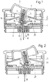
- the toggle button 3 e.g. about circular cylindrical lugs 4 in corresponding projecting recesses and be rotatable in this can or in the corresponding housing-fixed projections protrude a suitable recess in the rocker switch.
- the toggle button 3 has a guide projection 5, in which a Actuator 6 is guided.
- the actuator is pretensioned by a spring 7, which the actuator 6 from the guide approach 5th tries to push it out.
- this is based conically or cut-shaped front link end 8 from a rocker switch 9, which in turn with its opposite Surface is supported on a housing extension 10.
- the rocker switch 9 is in one via a cutting bearing 11 base plate-fixed contact piece 12 stored.
- the Storage provided such that the rocker switch 9 in their longitudinal direction by a predetermined amount b can move the contact piece 12 before lateral Projections 13, 14 opposite the legs on a fork 15 Strike the upper end of the contact piece 12 in FIG. 1.
- the projection is therefore in the bearing shown in FIG. 1 14 on the legs of the fork 15. Furthermore are still in 5 projecting tabs 16, 17 are provided in the direction of the guide projection, which are arranged fixed to the housing and either with the housing 1 themselves or in one piece with the cover 2. Of course, such rags can also be separated manufactured and subsequently inserted into the housing will.
- the task of the tabs 16, 17 is, on the one hand, that Limit movement of the rocker switch 3, so that this in the 1 is locked and so after reaching the desired actuation position is not further depressed can be. At the same time, the tabs 16, 17 serve to intercept the inertial movement of the rocker switch 3, so that their movement is dampened.
- the rocker switch 9 thus moves as far as it does through the appropriate storage is possible to the right.
- the cutting bearing 11 is formed by a floating bearing 11, the rocker switch a clear path in the X direction allowed, which will be called b below.
- path b results from that the distance of the projections 13, 14 from the amount b is greater than the width of the fork extension 15.
- the contact should be comparatively less Apply force without bouncing, after which the contact force increases and with a large contact force, the movement in the x direction by the amount b is made.
- the invention is therefore suitable for all switches, the one have their position changing rocker switch, it it is irrelevant whether the switch has a slide button or operated by a rocker switch.
- the invention is not only for on / off switches, but also suitable for changeover switch, the stop according to the invention (21) essentially symmetrically opposite each other arranged on the rocker on both sides of the bearing becomes. such as B. the second stop (22) shows.
Landscapes
- Mechanisms For Operating Contacts (AREA)
- Tumbler Switches (AREA)
- Push-Button Switches (AREA)
Description
- Fig. 1
- einen Kippschalter in einer ersten Stellung und
- Fig. 2
- den Kippschalter nach Fig. 1 in einer zweiten Stellung.
Claims (8)
- Kippschalter, bei dem eine gegenüber dem Gehäuse (1) gelagerte Schaltwippe (9) durch ein Betätigungsglied (6) mit einer einen sich längs der Schaltwippe (9) verschiebenden Angriffspunkt (8) aufweisenden Kraft beaufschlagt wird, wobei vor dem Überschreiten des gehäusefesten Lagerortes (11) die Schaltwippe (9) eine erste stabile Stellung und nach dem Überschreiten des Lagerortes (11) die Wippe eine zweite stabile Stellung einnimmt, dadurch gekennzeichnet, daß die Bewegungsbahn (18) für den Angriffspunkt (8) des Betätigungsglieds (6) auf der Schaltwippe in deren Längsrichtung derart ausgeformt ist, daß die Bewegung des Betätigungsglieds (6) erst durch einen Anschlag an der Schaltwippe (9) begrenzt wird, nachdem die Schaltwippe (9) ihre neue stabile Stellung erreicht hat.
- Kippschalter nach Anspruch 1, dadurch gekennzeichnet, daß zur Bildung des Anschlages (21) die Kurvenbahn (18) der Schaltwippe (9) für das Schaltglied derart gekrümmt ist, daß eine die Bewegung des Betätigungsgliedes (6) begrenzende Kraft (X) vorzugsweise progressiv aufgebaut wird.
- Kippschalter nach einem der vorangegangenen Ansprüche, dadurch gekennzeichnet, daß in der durch den Anschlag (21) begrenzten Endstellung für das Betätigungsglied (6) durch dieses eine Kraft (X) in Längsrichtung der Schaltwippe (9) ausgeübt wird.
- Kippschalter nach einem der vorangegangenen Ansprüche, dadurch gekennzeichnet, daß die Schaltwippe (9) gegenüber dem Gehäuse (1) in einem Schneidlager (11) gelagert ist und daß das Betätigungsglied (6) gegenüber dem Gehäuse drehbar gelagert ist.
- Kippschalter nach Anspruch 4, dadurch gekennzeichnet, daß die Schaltwippe (9) gegenüber dem gehäusefesten Lagerort (11) in Längsrichtung (X) der Schaltwippe (9) schwimmend gelagert ist und das die gehäusefeste Lagerfläche (11) in einem gleichzeitig einen elektrischen Anschluß für den Schalter darstellendes Lagerstück (12) gebildet ist.
- Kippschalter nach einem der vorangegangenen Ansprüche, dadurch gekennzeichnet, daß für die beiden Endstellungen der Schaltwippe (9) jeweils ein Anschlag (21, 22) in der Wippe (9) vorgesehen ist.
- Kippschalter nach einem der vorangegangenen Ansprüche, dadurch gekennzeichnet, daß der Anschlag (21) derart ausgeformt ist, daß ein an der Schaltwippe (9) befestigter Wippenkontakt (19) erst auf den Schaltkontakt (2) eines gehäusefesten Kontaktstücks aufsetzt und danach der Wippenkontakt (19) über den Schaltkontakt (20) durch die in Längsrichtung der Wippe wirkende Kraft (X) schleifend verschoben wird.
- Kippschalter nach einem der vorangegangenen Ansprüche, dadurch gekennzeichnet, daß das Betätigungsglied (6) in seiner Längsrichtung federnd gegenüber der Schaltwippe (9) gelagert ist.
Applications Claiming Priority (2)
| Application Number | Priority Date | Filing Date | Title |
|---|---|---|---|
| DE4326312 | 1993-08-05 | ||
| DE4326312A DE4326312A1 (de) | 1993-08-05 | 1993-08-05 | Kippschalter mit Anschlag zur Geräuschdämpfung |
Publications (2)
| Publication Number | Publication Date |
|---|---|
| EP0638915A1 EP0638915A1 (de) | 1995-02-15 |
| EP0638915B1 true EP0638915B1 (de) | 1998-03-18 |
Family
ID=6494530
Family Applications (1)
| Application Number | Title | Priority Date | Filing Date |
|---|---|---|---|
| EP94111920A Expired - Lifetime EP0638915B1 (de) | 1993-08-05 | 1994-07-30 | Kippschalter mit Anschlag zur Geräuschdämpfung |
Country Status (2)
| Country | Link |
|---|---|
| EP (1) | EP0638915B1 (de) |
| DE (2) | DE4326312A1 (de) |
Families Citing this family (8)
| Publication number | Priority date | Publication date | Assignee | Title |
|---|---|---|---|---|
| DE19541380A1 (de) * | 1995-11-07 | 1997-05-15 | Teves Gmbh Alfred | Schalter mit auf die Leiterplatte aufgerasteten Schaltmodulen |
| US7436391B2 (en) | 2002-10-09 | 2008-10-14 | Siemens Aktiengesellschaft | Navigation switch |
| DE10247093B3 (de) * | 2002-10-09 | 2004-06-09 | Siemens Ag | Navigationsschalter |
| DE102006041951B4 (de) * | 2006-08-30 | 2022-05-05 | Deltatech Controls Usa, Llc | Wippschalter |
| FR2924266B1 (fr) * | 2007-11-27 | 2009-12-25 | Legrand France | Appareil electrique tel qu'un interrupteur |
| CN102990621B (zh) * | 2012-12-04 | 2015-01-07 | 张家港华捷电子有限公司 | 电动工具用开关 |
| FR3022069B1 (fr) * | 2014-06-05 | 2016-07-01 | Legrand France | Commutateur electrique silencieux |
| DE102014109600B4 (de) | 2014-07-09 | 2016-06-02 | Eq-3 Entwicklung Gmbh | Wippenschaltelement |
Family Cites Families (14)
| Publication number | Priority date | Publication date | Assignee | Title |
|---|---|---|---|---|
| DE1865169U (de) * | 1962-10-30 | 1963-01-10 | Vedder Gmbh Geb | Drucktaster. |
| DE1907867U (de) * | 1964-08-26 | 1965-01-07 | Kirsten Elektrotech | Mehrfachkipphebelreihenschalter. |
| DE1903576U (de) * | 1964-09-03 | 1964-11-05 | J & J Marquardt Spezialfabrik | Gehaeuse fuer elektrische schalter. |
| DE7043491U (de) * | 1970-11-25 | 1971-07-29 | Siemens Gmbh | Rahmenrastschalter |
| DE7213814U (de) * | 1972-04-13 | 1972-07-20 | Giersiepen G Elektrotechnische Ind | Elektrisches Installationsgerät, insbesondere Schalter |
| DE7833309U1 (de) * | 1978-11-09 | 1979-02-15 | Gebrueder Merten Gmbh & Co Kg, 5270 Gummersbach | Elektrischer Installationsschalter |
| DE2912363A1 (de) * | 1979-03-29 | 1980-10-16 | Rau Swf Autozubehoer | Elektrischer schalter mit einer handhabe |
| GB2052866B (en) * | 1979-05-03 | 1983-12-07 | Hoover Ltd | Electric switch |
| DE7931034U1 (de) * | 1979-11-02 | 1980-01-31 | Gebr. Vedder Gmbh, 5885 Schalksmuehle | Installationsschalter |
| GB8402386D0 (en) * | 1984-01-30 | 1984-02-29 | Chaplin Tanner Products Ltd | Electrical switch |
| NZ218566A (en) * | 1986-12-09 | 1990-12-21 | Pdl Holdings Ltd | Slow break, fast make rocker activated switch |
| SU1494067A1 (ru) * | 1987-06-10 | 1989-07-15 | Специальное Конструкторское Бюро Харьковского Электроаппаратного Завода | Клавишный выключатель |
| DE3915767C3 (de) * | 1989-05-13 | 1999-01-21 | Teves Gmbh Alfred | Elektrisches Gerät |
| FR2698719B1 (fr) * | 1992-12-02 | 1995-02-03 | Arnould App Electr | Mécanisme d'interrupteur à organe auxiliaire associé au balai conducteur. |
-
1993
- 1993-08-05 DE DE4326312A patent/DE4326312A1/de not_active Withdrawn
-
1994
- 1994-07-30 DE DE59405458T patent/DE59405458D1/de not_active Expired - Lifetime
- 1994-07-30 EP EP94111920A patent/EP0638915B1/de not_active Expired - Lifetime
Also Published As
| Publication number | Publication date |
|---|---|
| EP0638915A1 (de) | 1995-02-15 |
| DE59405458D1 (de) | 1998-04-23 |
| DE4326312A1 (de) | 1995-02-09 |
Similar Documents
| Publication | Publication Date | Title |
|---|---|---|
| DE4104572A1 (de) | Zweistufiger, gummiumhuellter schalter | |
| DE4205364C2 (de) | Kippschalter | |
| DE829759C (de) | Elektrischer Tumblerschalter | |
| DE4215097C2 (de) | Schalteranordnung | |
| DE2630356A1 (de) | Elektrischer schalter | |
| EP0638915A1 (de) | Kippschalter mit Anschlag zur Geräuschdämpfung | |
| DE3942925C2 (de) | ||
| DE4240218C2 (de) | Schaltvorrichtung | |
| DE3532740A1 (de) | Verschiebbares elektrisches bauteil, insbesondere fuer schiebeschalter | |
| DE3739296A1 (de) | Impulsgenerator | |
| DE2553009A1 (de) | Schalter fuer einen fahrtrichtungsanzeiger | |
| DE3513803C2 (de) | ||
| DE2940174C2 (de) | Elektrischer Schalter, insbesondere für Kraftfahrzeuge | |
| DE3940285C2 (de) | ||
| DE2827854C2 (de) | Elektrischer Wippenschalter | |
| DE2240728A1 (de) | Regelbarer widerstand | |
| DE3115793A1 (de) | Elektrischer schalter | |
| DE2228676C3 (de) | Stromstoßschalter | |
| EP0428475B1 (de) | Niederspannungs-Leistungsschalter mit einer Hebelkontaktanordnung | |
| DE3629290C2 (de) | ||
| DE3406010C1 (de) | Gehäuse für ein elektrisch betriebenes Gerät, insbesondere ein Bildschirmgerät | |
| DE1615777C3 (de) | ||
| DE3412377C2 (de) | ||
| DE3339208C2 (de) | Steuerschaltgerät | |
| DE691897C (de) | Periodischer Umschalter fuer Wechselrichter |
Legal Events
| Date | Code | Title | Description |
|---|---|---|---|
| PUAI | Public reference made under article 153(3) epc to a published international application that has entered the european phase |
Free format text: ORIGINAL CODE: 0009012 |
|
| 17P | Request for examination filed |
Effective date: 19940730 |
|
| AK | Designated contracting states |
Kind code of ref document: A1 Designated state(s): DE FR IT |
|
| 17Q | First examination report despatched |
Effective date: 19960624 |
|
| GRAG | Despatch of communication of intention to grant |
Free format text: ORIGINAL CODE: EPIDOS AGRA |
|
| ITF | It: translation for a ep patent filed | ||
| GRAG | Despatch of communication of intention to grant |
Free format text: ORIGINAL CODE: EPIDOS AGRA |
|
| GRAH | Despatch of communication of intention to grant a patent |
Free format text: ORIGINAL CODE: EPIDOS IGRA |
|
| GRAH | Despatch of communication of intention to grant a patent |
Free format text: ORIGINAL CODE: EPIDOS IGRA |
|
| GRAA | (expected) grant |
Free format text: ORIGINAL CODE: 0009210 |
|
| AK | Designated contracting states |
Kind code of ref document: B1 Designated state(s): DE FR IT |
|
| REF | Corresponds to: |
Ref document number: 59405458 Country of ref document: DE Date of ref document: 19980423 |
|
| ET | Fr: translation filed | ||
| PLBE | No opposition filed within time limit |
Free format text: ORIGINAL CODE: 0009261 |
|
| STAA | Information on the status of an ep patent application or granted ep patent |
Free format text: STATUS: NO OPPOSITION FILED WITHIN TIME LIMIT |
|
| 26N | No opposition filed | ||
| REG | Reference to a national code |
Ref country code: FR Ref legal event code: D6 |
|
| PGFP | Annual fee paid to national office [announced via postgrant information from national office to epo] |
Ref country code: IT Payment date: 20080726 Year of fee payment: 15 |
|
| PG25 | Lapsed in a contracting state [announced via postgrant information from national office to epo] |
Ref country code: IT Free format text: LAPSE BECAUSE OF NON-PAYMENT OF DUE FEES Effective date: 20090730 |
|
| PGFP | Annual fee paid to national office [announced via postgrant information from national office to epo] |
Ref country code: DE Payment date: 20130709 Year of fee payment: 20 |
|
| PGFP | Annual fee paid to national office [announced via postgrant information from national office to epo] |
Ref country code: FR Payment date: 20130731 Year of fee payment: 20 |
|
| REG | Reference to a national code |
Ref country code: DE Ref legal event code: R071 Ref document number: 59405458 Country of ref document: DE |
|
| PG25 | Lapsed in a contracting state [announced via postgrant information from national office to epo] |
Ref country code: DE Free format text: LAPSE BECAUSE OF EXPIRATION OF PROTECTION Effective date: 20140731 |