EP0633980B1 - Spiralmaschine mit überhitzungsschutz - Google Patents
Spiralmaschine mit überhitzungsschutz Download PDFInfo
- Publication number
- EP0633980B1 EP0633980B1 EP92917788A EP92917788A EP0633980B1 EP 0633980 B1 EP0633980 B1 EP 0633980B1 EP 92917788 A EP92917788 A EP 92917788A EP 92917788 A EP92917788 A EP 92917788A EP 0633980 B1 EP0633980 B1 EP 0633980B1
- Authority
- EP
- European Patent Office
- Prior art keywords
- motor
- valve
- gas
- scroll compressor
- compressor
- Prior art date
- Legal status (The legal status is an assumption and is not a legal conclusion. Google has not performed a legal analysis and makes no representation as to the accuracy of the status listed.)
- Expired - Lifetime
Links
Images


Classifications
-
- F—MECHANICAL ENGINEERING; LIGHTING; HEATING; WEAPONS; BLASTING
- F04—POSITIVE - DISPLACEMENT MACHINES FOR LIQUIDS; PUMPS FOR LIQUIDS OR ELASTIC FLUIDS
- F04C—ROTARY-PISTON, OR OSCILLATING-PISTON, POSITIVE-DISPLACEMENT MACHINES FOR LIQUIDS; ROTARY-PISTON, OR OSCILLATING-PISTON, POSITIVE-DISPLACEMENT PUMPS
- F04C18/00—Rotary-piston pumps specially adapted for elastic fluids
- F04C18/02—Rotary-piston pumps specially adapted for elastic fluids of arcuate-engagement type, i.e. with circular translatory movement of co-operating members, each member having the same number of teeth or tooth-equivalents
-
- F—MECHANICAL ENGINEERING; LIGHTING; HEATING; WEAPONS; BLASTING
- F04—POSITIVE - DISPLACEMENT MACHINES FOR LIQUIDS; PUMPS FOR LIQUIDS OR ELASTIC FLUIDS
- F04C—ROTARY-PISTON, OR OSCILLATING-PISTON, POSITIVE-DISPLACEMENT MACHINES FOR LIQUIDS; ROTARY-PISTON, OR OSCILLATING-PISTON, POSITIVE-DISPLACEMENT PUMPS
- F04C28/00—Control of, monitoring of, or safety arrangements for, pumps or pumping installations specially adapted for elastic fluids
- F04C28/28—Safety arrangements; Monitoring
-
- F—MECHANICAL ENGINEERING; LIGHTING; HEATING; WEAPONS; BLASTING
- F04—POSITIVE - DISPLACEMENT MACHINES FOR LIQUIDS; PUMPS FOR LIQUIDS OR ELASTIC FLUIDS
- F04B—POSITIVE-DISPLACEMENT MACHINES FOR LIQUIDS; PUMPS
- F04B49/00—Control, e.g. of pump delivery, or pump pressure of, or safety measures for, machines, pumps, or pumping installations, not otherwise provided for, or of interest apart from, groups F04B1/00 - F04B47/00
- F04B49/10—Other safety measures
-
- F—MECHANICAL ENGINEERING; LIGHTING; HEATING; WEAPONS; BLASTING
- F04—POSITIVE - DISPLACEMENT MACHINES FOR LIQUIDS; PUMPS FOR LIQUIDS OR ELASTIC FLUIDS
- F04B—POSITIVE-DISPLACEMENT MACHINES FOR LIQUIDS; PUMPS
- F04B2203/00—Motor parameters
- F04B2203/02—Motor parameters of rotating electric motors
- F04B2203/0205—Temperature
-
- F—MECHANICAL ENGINEERING; LIGHTING; HEATING; WEAPONS; BLASTING
- F04—POSITIVE - DISPLACEMENT MACHINES FOR LIQUIDS; PUMPS FOR LIQUIDS OR ELASTIC FLUIDS
- F04B—POSITIVE-DISPLACEMENT MACHINES FOR LIQUIDS; PUMPS
- F04B2205/00—Fluid parameters
- F04B2205/11—Outlet temperature
-
- F—MECHANICAL ENGINEERING; LIGHTING; HEATING; WEAPONS; BLASTING
- F04—POSITIVE - DISPLACEMENT MACHINES FOR LIQUIDS; PUMPS FOR LIQUIDS OR ELASTIC FLUIDS
- F04C—ROTARY-PISTON, OR OSCILLATING-PISTON, POSITIVE-DISPLACEMENT MACHINES FOR LIQUIDS; ROTARY-PISTON, OR OSCILLATING-PISTON, POSITIVE-DISPLACEMENT PUMPS
- F04C2270/00—Control; Monitoring or safety arrangements
- F04C2270/19—Temperature
-
- F—MECHANICAL ENGINEERING; LIGHTING; HEATING; WEAPONS; BLASTING
- F04—POSITIVE - DISPLACEMENT MACHINES FOR LIQUIDS; PUMPS FOR LIQUIDS OR ELASTIC FLUIDS
- F04C—ROTARY-PISTON, OR OSCILLATING-PISTON, POSITIVE-DISPLACEMENT MACHINES FOR LIQUIDS; ROTARY-PISTON, OR OSCILLATING-PISTON, POSITIVE-DISPLACEMENT PUMPS
- F04C2270/00—Control; Monitoring or safety arrangements
- F04C2270/70—Safety, emergency conditions or requirements
-
- F—MECHANICAL ENGINEERING; LIGHTING; HEATING; WEAPONS; BLASTING
- F05—INDEXING SCHEMES RELATING TO ENGINES OR PUMPS IN VARIOUS SUBCLASSES OF CLASSES F01-F04
- F05B—INDEXING SCHEME RELATING TO WIND, SPRING, WEIGHT, INERTIA OR LIKE MOTORS, TO MACHINES OR ENGINES FOR LIQUIDS COVERED BY SUBCLASSES F03B, F03D AND F03G
- F05B2270/00—Control
- F05B2270/30—Control parameters, e.g. input parameters
- F05B2270/303—Temperature
- F05B2270/3032—Temperature excessive temperatures, e.g. caused by overheating
Definitions
- the present invention relates to scroll compressors.
- a typical scroll compressor has an orbiting scroll member having a spiral wrap on one face thereof, a non-orbiting scroll member having a spiral wrap on one face thereof with said wraps being intermeshed with one another, and means for causing said orbiting scroll member to orbit about an axis with respect to said non-orbiting scroll member, whereby said wraps will create pockets of progressively decreasing volume from a suction zone to a discharge zone.
- EP-A-0 375 207 upon which the preamble of claim 1 is based, discloses a scroll compressor in which an internal chamber pressure is sensed. Control means are provided for de-energizing the compressor drive motor if the sensed pressure is above or below a predetermined value.
- EP-A-0 480 560 is relevant to the present case as prior art only under Article 54(3) EPC.
- EP-A-0 480 560 discloses a scroll compressor in which a thermally responsive valve arrangement is provided to provide high temperature protection.
- the valve arrangement is arranged to cause a high-side to low-side leak through a passage when excessive gas discharge temperatures are encountered, thereby causing the motor protector to trip so as to de-energize the drive motor.
- the valve arrangement leaks gas from the high-side to the low-side through a passage provided either in the non-orbiting scroll member or in a partition between the high-side and low-side of the compressor.
- the downstream side of the passage may be provided with a short L-shaped plastic extension tube to carry leaked gas closer to the motor space.
- a scroll compressor comprising:
- the valve means may be a thermally responsive valve and the sensed condition may be gas temperature.
- the valve means is a pressure-responsive valve and the sensed condition is gas pressure.
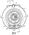
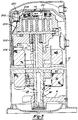
- the present invention is suitable for incorporation in many different types of scroll compressors, for exemplary purposes it will be described herein incorporated in a hermetic scroll refrigerant motor-compressor of the "low side" type (i.e., where the motor and compressor are cooled by suction gas in the hermetical shell, as illustrated in vertical section in Figure 1).
- the compressor comprises a cylindrical hermetic shell 10 having welded at the upper end thereof a cap 12, which is provided with a refrigerant discharge fitting 14 optionally having the usual discharge valve therein (not shown).
- affixed to the shell include a transversely extending partition 16 which is welded about its periphery at the same point that cap 12 is welded to shell 10, a main bearing housing 18 which is affixed to shell 10 at a plurality of points in any desirable manner, and a suction gas inlet fitting 17 having a gas deflector 19 disposed in communication therewith inside the shell.
- a motor stator 20 which is generally square in cross-section but with the corners rounded off is press fit into shell 10.
- the flats between the rounded corners on the stator provide passageways between the stator and shell, indicated at 22, which facilitate the flow of lubricant from the top of the shell to the bottom.
- a crankshaft 24 having an eccentric crank pin 26 at the upper end thereof is rotatably journaled in a bearing 28 in main bearing housing 18 and a second bearing 42 in a lower bearing housing 41.
- Crankshaft 24 has at the lower end the usual relatively large diameter oil-pumping concentric bore 43 which communicates with a radially outwardly inclined smaller diameter bore 30 extending upwardly therefrom to the top of the crankshaft.
- the lower portion of the interior shell 10 is filled with lubricating oil in the usual manner and the pump at the bottom of the crankshaft is the primary pump acting in conjunction with bore 30, which acts as a secondary pump, to pump lubricating fluid to all the various portions of the compressor which require lubrication.
- Crankshaft 24 is rotatively driven by an electric motor including stator 20 having windings 32 passing therethrough, and a rotor 34 press fit on the crankshaft and having one or more counterweights 36.
- a motor protector 35 of the usual type, is provided in close proximity to motor windings 32 so that if the motor exceeds its normal temperature range the protector will de-energize the motor.
- main bearing housing 18 The upper surface of main bearing housing 18 is provided with an annular flat thrust bearing surface 38 on which is disposed an orbiting scroll member 40 comprising an end plate 42 having the usual spiral vane or wrap 44 on the upper surface thereof, an annular flat thrust surface 46 on the lower surface, and projecting downwardly therefrom a cylindrical hub 48 having a journal bearing 50 therein and in which is rotatively disposed a drive bushing 52 having an inner bore 54 in which crank pin 26 is drivingly disposed.
- Crank pin 26 has a flat on one surface (not shown) which drivingly engages a flat surface in a portion of bore 54 (not shown) to provide a radially compliant driving arrangement, such as shown in assignee's U.S. Letters Patent No. 4,877,382, the disclosure of which is herein incorporated by reference.
- non-orbiting scroll member 58 has a plurality of circumferentially spaced mounting bosses 60, one of which is shown, each having a flat upper surface 62 and an axial bore 64 in which is slidably disposed a sleeve 66 which is bolted to main bearing housing 18 by a bolt 68 in the manner shown.
- Bolt 68 has an enlarged head having a flat lower surface 70 which engages surface 62 to limit the axially upper or separating movement of non-orbiting scroll member, movement in the opposite direction being limited by axial engagement of the lower tip surface of wrap 56 and the flat upper surface of orbiting scroll member 40.
- Non-orbiting scroll member 58 has a centrally disposed discharge passageway 72 communicating with an upwardly open recess 74 which is in fluid communication via an opening 75 in partition 16 with the discharge muffler chamber 76 defined by cap 12 and partition 16.
- An intermediate pressure relief valve 220 is disposed between the discharge muffler chamber 76 and the interior of shell 10. The intermediate relief valve 220 will open at a specified excessive pressure and vent pressurized gas from the discharge muffler chamber 76 to the ducting system 200.
- Non-orbiting scroll member 58 has in the upper surface thereof an annular recess 78 having parallel coaxial side walls in which is sealingly disposed for relative axial movement an annular floating seal 80 which serves to isolate the bottom of recess 78 from the presence of gas under suction and discharge pressure so that it can be placed in fluid communication with a source of intermediate fluid pressure by means of a passageway 81.
- the non-orbiting scroll member is thus axially biased against the orbiting scroll member by the forces created by discharge pressure acting on the central portion of scroll member 58 and those created by intermediate fluid pressure acting on the bottom of recess 78.
- This axial pressure biasing, as well as various techniques for supporting scroll member 58 for limited axial movement, are disclosed in much greater detail in assignee's aforesaid U.S. Letters Patent No. 4,877,328.
- Oldham coupling comprising a ring 82 having a first pair of keys 84 (one of which is shown) slidably disposed in diametrically opposed slots 86 (one of which is shown) in scroll member 58 and a second pair of keys (not shown) slidably disposed in diametrically opposed slots in scroll member 40.
- seal 80 is of a coaxial sandwiched construction and comprises an annular base plate 100 having a plurality of equally spaced upstanding integral projections 102 each having an enlarged base portion 104. Disposed on plate 100 is an annular gasket 106 having a plurality of equally spaced holes which receive base portions 104, on top of which is disposed a pair of normally flat identical lower lip seals 108 formed of glass filled PTFE. Seals 108 have a plurality of equally spaced holes which receive base portions 104.
- annular spacer plate 110 On top of seals 108 is disposed an annular spacer plate 110 having a plurality of equally spaced holes which receive base portions 104, and on top of plate 110 are a pair of normally flat identical annular upper lip seals 112 formed of a same material as lip seals 108 and maintained in coaxial position by means of an annular upper seal plate 114 having a plurality of equally spaced holes receiving projections 102.
- Seal plate 114 has disposed about the inner periphery thereof an upwardly projecting planar sealing lip 116. The assembly is secured together by swaging the ends of each of the projections 102, as indicated at 118.
- the overall seal assembly therefor provides three distinct seals; namely, an inside diameter seal at 124 and 126, an outside diameter seal at 128 and a top seal at 130, as best seen in Figure 1.
- Seal 124 is between the inner periphery of lip seals 108 and the inside wall of recess 78
- seal 126 is between the inner periphery of lip seals 112 and the inside wall of recess 78.
- Seals 124 and 126 isolate fluid under intermediate pressure in the bottom of recess 78 from fluid under discharge pressure in recess 74.
- Seal 128 is between the outer periphery of lip seals 108 and the outer wall of recess 78 , and isolates fluid under intermediate pressure in the bottom of recess 78 from fluid at suction pressure within shell 10.
- Seal 130 is between lip seal 116 and an annular wear ring 132 surrounding opening 75 in partition 16, and isolates fluid at suction pressure from fluid at discharge pressure across the top of the seal assembly.
- seal 80 The details of construction of seal 80 are more fully described in applicant's assignee's copending application for U.S. Letters Patent, Serial No. 07/591,454, filed October 1, 1990 and entitled Scroll Machine With Floating Seal, the disclosure of which is hereby incorporated herein by reference.
- the compressor is preferably of the "low side" type in which suction gas entering via deflector 19 is allowed, in part, to escape into the shell and assist in cooling the motor. So long as there is an adequate flow of returning suction gas the motor will remain within desired temperature limits. When this flow drops significantly, however, the loss of cooling will eventually cause motor protector 35 to trip and shut the machine down.
- the scroll compressor as thus far broadly described with the exception of ducting system 200 is either now known in the art or is the subject matter of other pending applications for patent by applicant's assignee.
- the details of construction which incorporate the principles of the present invention are those which deal with a unique temperature responsive valve assembly, indicated generally at 134, and a system for ducting discharge gases closer to the motor space, indicated generally at 200.
- the temperature responsive valve 146 and the intermediate pressure relief valve 220 cause the compressor to cease any significant pumping if the discharge gas reaches excessive temperatures or pressures respectively. The ceasing of pumping action deprives the motor of its normal flow of cooling gas.
- the excessive temperature discharge gas is ducted directly to the lower portion of motor space where it is circulated around and through the motor thus increasing the temperature of the stator 20 and the windings 32.
- This increase in temperature of the stator 20 and the windings 32 in conjunction with the circulating excessive temperature discharge gas will heat the standard motor protector 35 which will then trip and de-energize the motor.
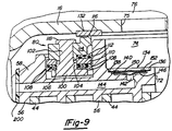
- the temperature responsive valve assembly 134 of the present invention comprises a circular valve cavity 136 disposed in the bottom of recess 74 and having annular coaxial peripheral steps 138 and 140 of decreasing diameter, respectively.
- the bottom of cavity 136 communicates with an axial passage 142 of circular cross-section, which in turn communicates with a radial passage 144, the radially outer outlet end of which is in communication with a ducting system 200 which is in turn in communication with suction gas within shell 10.
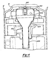
- the ducting system 200 consists of a first generally partially annular section 202, a funneling section 204 and a second partially annular section 206.
- the first generally partially annular section 202 is shaped to communicate with both the radial passage 144 and the pressure relief valve 220.
- the actual shape of annular section 202 is such that it easily fits into the open area in the upper portion of the motor/compressor assembly.
- the annular section 202 has a circular opening 208 which is in communication with radial passage 144.
- the annular section 202 acts as an accumulator for the excessive temperature discharge gas.
- the annular section 202 also surrounds the intermediate pressure relief valve 220 in order to direct any of the excessive pressure discharge gas which is released by relief valve 220 to specific areas within the shell 10.
- the annular section 202 is in communication with the funneling section 204 which funnels the excessive temperature discharge gas to annular section 206 which is also in communication with funneling section 204.
- the discharge end of the annular section 206 is positioned to direct the excessive temperature discharge gas to the lower portion of the shell 10 as shown in Figure 3 and more specifically to one of the passageways 22 the valve will "snap" into its open position in which is slightly concave upwardly with its outer periphery engaging step 140 and its center valving portion elevated away from the valve seat. In this position, high pressure discharge fluid can leak through holes 148 and passages 142 and 144 to the interior of annular section 202, to the funneling section 204, to the second annular section 206 and finally to the lower portion of the shell 10.
- the suction action of the compressor would limit the amount of circulation within the shell 10 of the excessive temperature gas.
- the excessive temperature gas will go through the compressor again and have its temperature increased further. This continuous increase of the temperature of the discharge gas will continue until the motor protector 35 trips.
- the delay caused by the limited recirculation of the discharge gas can allow the discharge gas to reach temperatures which are above those desired.
- valve assembly 134 is located on partition 16 rather than in recess 74 where there could be serious space constraints in certain compressor designs.
- valve assembly 134 is mounted in a fitting 158 which is secured to partition 16 in a fluid bore 160 in any suitable manner, with the bottom of fitting 158 extending radially between the stator 20 and outer shell 10.
- This excessive discharge gas circulates through passageway 22 and the areas around the motor stator 20. The gas is drawn through the gap between the motor stator 20 and rotor 34 as shown by the arrows in Figure 3.
- the excessive temperature discharge gas serves to further heat the motor protector, the motor stator, windings and rotor. This increase in heat, coupled with the loss of normal cooling suction gas will cause the motor protector 35 to trip and de-energize the motor.
- passage 142 The intersection of passage 142 and the planar bottom of cavity 136 defines a circular valve seat, in which is normally disposed the spherical center valving portion of a circular slightly spherical relatively thin saucer-like bimetallic valve 146 having a plurality of through holes 148 disposed outwardly of the spherical valving portion.
- Valve 146 is retained in place by a circular generally annular spider-like retainer ring 150 which has an open center portion and a plurality of spaced radially outwardly extending fingers 152 which are normally of a slightly larger diameter than the side wall of cavity 136. After valve 146 is assembled in place, retainer 150 is pushed into cavity 136 until it bottoms out on step 138, and is held in place by fingers 152 which bitingly engage the side wall of cavity 136. In Figure 9 valve 146 is shown in its normally closed position (i.e., slightly concave downwardly with its peripheral rim disposed between retainer 150 and step 140 and its center valving portion closing passageway 142.
- valve 146 Being disposed in discharge gas recess 74, valve 146 is fully exposed to the temperature of the discharge gas very close to the point it exits the scroll wraps (obviously, the closer the location at which the discharge gas temperature is sensed is to the actual temperature of the discharge gas existing in the last scroll compression pocket the more accurately the machine will be controlled in response to discharge pressure).
- the materials of bimetallic valve 146 are chosen, using conventional criteria, so that when discharge gas temperature reaches a predetermined value which is considered excessive, being spaced slightly from the bottom of bore 160 to define a cavity 162.
- the top of the valve assembly is exposed to discharge gas in discharge muffler 76, and when excessive temperatures are encountered valve 146 opens to permit leaking from the discharge muffler through the valve into cavity 162 via passage 142.
- FIG. 7 and 8 is essentially the same in design and function as the embodiment of Figures 5 and 6 except that there is provided an L-shaped tube 168 having one end disposed in a bore 170 in fitting 158, which communicates with valve cavity 136, and the opposite end disposed immediately adjacent discharge port 72, for the purpose of making the valve more sensitive to temperatures closer to the compressing mechanism. The closer the temperature sensed is to the actual compressor discharge gas temperature, the more accurate and reliable is the control.
Landscapes
- Engineering & Computer Science (AREA)
- Mechanical Engineering (AREA)
- General Engineering & Computer Science (AREA)
- Applications Or Details Of Rotary Compressors (AREA)
- Rotary Pumps (AREA)
- Safety Valves (AREA)
- Information Retrieval, Db Structures And Fs Structures Therefor (AREA)
Claims (13)
- Spiralverdichter, miteinem hermetischen Gehäuse (10) mit einem Motorhohlraum,einem umlaufenden Spiralelement (40), das sich in dem Gehäuse befindet und auf einer Seitenfläche davon eine erste Spiralhülle (44) aufweist,einem nicht umlaufenden Spiralelement (56), das sich in dem Gehäuse befindet und auf einer Seitenfläche davon eine zweite Spiralhülle aufweist, wobei die Hüllen ineinandergreifen,einem Motor (20, 34), der einen Motorstator (20) aufweist, wobei sich der Motor in dem Motorhohlraum des Gehäuses befindet, um zu bewirken, daß das umlaufende Spiralelement (40) um eine Achse relativ zu dem nicht umlaufenden Spiralelement (56) umläuft, wodurch diese Hüllen Taschen mit einem stetig abnehmenden Volumen von einer Ansaugzone zu einer Auslaßzone schaffen, und mitMitteln (17) zum Einführen von Sauggas in das Gehäuse (10),dadurch gekennzeichnet, daß der Verdichter desweiteren folgendes umfaßt:Durchgangsmittel (200), die einen Durchgang bilden, der ein Einlaßende und ein Auslaßende aufweist, wobei der Durchgang an seinem Einlaßende mit einem Ventilmittel (134) in Fluidverbindung steht und sich in den Motorhohlraum erstreckt, um an seinem Auslaßende nahe dem Motorstator zu enden, wobei das Ventilmittel (134) dazu dient, den Gasdurchfluß durch den Durchgang (200) zu steuern, und in Reaktion auf eine erfaßte Bedingung derart betätigt wird, daß es von einem normalerweise geschlossenen Zustand in einen offenen Zustand umgeschaltet wird, so daß es den Durchgang öffnet und dadurch das Ausströmen von Druckgas durch den Durchgang ausgehend von der Auslaßzone zu der Ansaugzone bis zu einem Bereich nahe dem Motorstator (20) erlaubt, undin der Ansaugzone einen Wärmeschutzschalter (35), der dem Motor (20, 34) zugeordnet ist, um den Motor zu deaktivieren, wenn der Wärmeschutzschalter eine vorbestimmte unzulässige Temperatur erreicht, und wobei das Ausströmen des Druckgases einen Anstieg der Temperatur des Motors und des Wärmeschutzschalters bewirkt, wodurch bewirkt wird, daß der Wärmeschutzschalter die zu hohe Temperatur erreicht und den Motor abschaltet.
- Spiralverdichter nach Anspruch 1, bei dem das Ventilmittel (134) ein auf Wärme reagierendes Ventil (146) ist und die erfaßte Bedingung die Gastemperatur ist.
- Spiralverdichter nach Anspruch 2, bei dem das Ventilmittel ein bimetallisches Ventilelement (146) umfaßt.
- Spiralverdichter nach Anspruch 3, bei dem das Ventilelement (146) eine kreisrunde scheibenförmige Konfiguration aufweist und einen im allgemeinen sphärischen mittleren Ventilabschnitt aufweist, wobei das Durchgangsmittel einen ringförmigen Absatz umfaßt, der als eine Ventilabdichtung dient, mit dem der sphärische Ventilabschnitt in Eingriff kommen kann.
- Spiralverdichter nach Anspruch 4, bei dem das Ventilelement (146) eine Vielzahl von Bohrungen (148) dort hindurch aufweist, die von dem Ventilabschnitt beabstandet sind, um den Durchfluß von Gas dort hindurch zu ermöglichen, wenn es offen ist.
- Spiralverdichter nach einem der vorhergehenden Ansprüche, bei dem das Ventilmittel (134) von dem daran anliegenden Druckdifferential in einer normalerweise geschlossenen Position gehalten wird.
- Spiralverdichter nach einem der vorhergehenden Ansprüche, desweiteren mit Mitteln, die einen Auslaßweg (72) durch das nicht umlaufende Spiralelement bilden, durch den das Druckgas die Taschen an dem Ende jedes Verdichtungszyklus verläßt, wobei sich das Ventilmittel (146) in einem Ventilhohlraum in der Wand des Auslaßwegs befindet.
- Spiralverdichter nach Anspruch 7, bei dem der Auslaßweg (72) eine erste axiale Bohrung mit einem relativ kleinen Durchmesser zur Aufnahme des Austrittsgases von den Taschen und eine zweite axiale Bohrung mit einem relativ großen Durchmesser zur Aufnahme des Austrittsgases von der ersten Bohrung umfaßt, wobei sich dieser Hohlraum in der zweiten Bohrung nahe bei dem Auslaß der ersten Bohrung befindet.
- Spiralverdichter nach Anspruch 8, bei dem die zweite Bohrung eine relativ flache quergerichtete axiale Innenfläche aufweist, von der ausgehend sich die erste Bohrung erstreckt, wobei sich der Ventilhohlraum in dieser Fläche befindet.
- Spiralverdichter nach einem der vorhergehenden Ansprüche, bei dem das Durchgangsmittel (200) in dem nicht umlaufenden Spiralelement (56) beginnt und sich der darin gebildete Durchgang ausgehend von dem Einlaßende radial in Richtung auf den äußeren Umfang des Spiralelements erstreckt.
- Spiralverdichter nach Anspruch 1, bei dem das Ventilmittel (134) ein auf Druck reagierendes Ventil ist und die erfaßte Bedingung der Gasdruck ist.
- Spiralverdichter nach einem der vorhergehenden Ansprüche, bei dem der Bereich nahe dem Motorstator (20) mit einer Öffnung zwischen dem Motorstator und dem hermetischen Gehäuse derart in Verbindung steht, daß das Druckgas in Richtung auf einen Abschnitt des Motors geleitet wird, der den Spiralelementen gegenüberliegt.
- Spiralverdichter nach einem der Ansprüche 1 bis 11, bei dem das Auslaßende des Durchgangs in einem radialen Raum (22) endet, der zwischen der Außenseite des Motorstators (20) und der Innenseite des hermetischen Gehäuses (10) ausgebildet ist.
Applications Claiming Priority (2)
| Application Number | Priority Date | Filing Date | Title |
|---|---|---|---|
| US07/591,428 US5141407A (en) | 1990-10-01 | 1990-10-01 | Scroll machine with overheating protection |
| PCT/US1992/002462 WO1993019295A1 (en) | 1990-10-01 | 1992-03-26 | Scroll machine with overheating protection |
Publications (3)
| Publication Number | Publication Date |
|---|---|
| EP0633980A1 EP0633980A1 (de) | 1995-01-18 |
| EP0633980A4 EP0633980A4 (de) | 1995-08-09 |
| EP0633980B1 true EP0633980B1 (de) | 1997-07-23 |
Family
ID=24366448
Family Applications (2)
| Application Number | Title | Priority Date | Filing Date |
|---|---|---|---|
| EP91305158A Expired - Lifetime EP0480560B1 (de) | 1990-10-01 | 1991-06-07 | Spiralmaschine mit Überhitzungsschutz |
| EP92917788A Expired - Lifetime EP0633980B1 (de) | 1990-10-01 | 1992-03-26 | Spiralmaschine mit überhitzungsschutz |
Family Applications Before (1)
| Application Number | Title | Priority Date | Filing Date |
|---|---|---|---|
| EP91305158A Expired - Lifetime EP0480560B1 (de) | 1990-10-01 | 1991-06-07 | Spiralmaschine mit Überhitzungsschutz |
Country Status (7)
| Country | Link |
|---|---|
| US (2) | US5141407A (de) |
| EP (2) | EP0480560B1 (de) |
| JP (2) | JP3084105B2 (de) |
| KR (1) | KR100194078B1 (de) |
| DE (2) | DE69121826T2 (de) |
| ES (1) | ES2091872T3 (de) |
| WO (1) | WO1993019295A1 (de) |
Families Citing this family (86)
| Publication number | Priority date | Publication date | Assignee | Title |
|---|---|---|---|---|
| US5141407A (en) * | 1990-10-01 | 1992-08-25 | Copeland Corporation | Scroll machine with overheating protection |
| US5186613A (en) * | 1991-12-20 | 1993-02-16 | American Standard Inc. | Reverse phase and high discharge temperature protection in a scroll compressor |
| US5248244A (en) * | 1992-12-21 | 1993-09-28 | Carrier Corporation | Scroll compressor with a thermally responsive bypass valve |
| US5290154A (en) * | 1992-12-23 | 1994-03-01 | American Standard Inc. | Scroll compressor reverse phase and high discharge temperature protection |
| US5368446A (en) * | 1993-01-22 | 1994-11-29 | Copeland Corporation | Scroll compressor having high temperature control |
| US5591014A (en) * | 1993-11-29 | 1997-01-07 | Copeland Corporation | Scroll machine with reverse rotation protection |
| US5366352A (en) * | 1993-12-13 | 1994-11-22 | Deblois Raymond L | Thermostatic compressor suction inlet duct valve |
| JP3173267B2 (ja) * | 1993-12-28 | 2001-06-04 | 松下電器産業株式会社 | スクロール圧縮機 |
| US5452989A (en) * | 1994-04-15 | 1995-09-26 | American Standard Inc. | Reverse phase and high discharge temperature protection in a scroll compressor |
| JP3517945B2 (ja) * | 1994-05-06 | 2004-04-12 | 三菱電機株式会社 | 車両用発電機 |
| US5707210A (en) * | 1995-10-13 | 1998-01-13 | Copeland Corporation | Scroll machine with overheating protection |
| US6017205A (en) * | 1996-08-02 | 2000-01-25 | Copeland Corporation | Scroll compressor |
| US6152700A (en) * | 1996-12-05 | 2000-11-28 | Maneurop | Hermetic compressor with remote temperature sensing means |
| US5951260A (en) * | 1997-05-01 | 1999-09-14 | Cummins Engine Company, Inc. | System and method for electronic air compressor control |
| US6095765A (en) | 1998-03-05 | 2000-08-01 | Carrier Corporation | Combined pressure ratio and pressure differential relief valve |
| WO2000020808A1 (fr) * | 1998-10-08 | 2000-04-13 | Zexel Valeo Climate Control Corporation | Cycle frigorifique |
| KR20000050614A (ko) * | 1999-01-12 | 2000-08-05 | 구자홍 | 스크롤 압축기의 과열 방지장치 |
| US6220839B1 (en) | 1999-07-07 | 2001-04-24 | Copeland Corporation | Scroll compressor discharge muffler |
| US6267565B1 (en) * | 1999-08-25 | 2001-07-31 | Copeland Corporation | Scroll temperature protection |
| US6341945B1 (en) * | 1999-10-18 | 2002-01-29 | Scroll Technologies | Scroll compressor with reduced capacity at high operating temperatures |
| US6302654B1 (en) * | 2000-02-29 | 2001-10-16 | Copeland Corporation | Compressor with control and protection system |
| US6406266B1 (en) * | 2000-03-16 | 2002-06-18 | Scroll Technologies | Motor protector on non-orbiting scroll |
| US6679683B2 (en) * | 2000-10-16 | 2004-01-20 | Copeland Corporation | Dual volume-ratio scroll machine |
| US6491500B1 (en) * | 2000-10-31 | 2002-12-10 | Scroll Technologies | Scroll compressor with motor protector in non-orbiting scroll and flow enhancement |
| US6418740B1 (en) * | 2001-02-22 | 2002-07-16 | Scroll Technologies | External high pressure to low pressure valve for scroll compressor |
| KR20020076185A (ko) * | 2001-03-27 | 2002-10-09 | 코우프랜드코포레이션 | 압축기 진단 시스템 |
| US6615594B2 (en) | 2001-03-27 | 2003-09-09 | Copeland Corporation | Compressor diagnostic system |
| KR100397561B1 (ko) * | 2001-08-20 | 2003-09-13 | 주식회사 엘지이아이 | 스크롤 압축기의 보호장치 |
| US8463441B2 (en) | 2002-12-09 | 2013-06-11 | Hudson Technologies, Inc. | Method and apparatus for optimizing refrigeration systems |
| JP4143827B2 (ja) * | 2003-03-14 | 2008-09-03 | 株式会社富士通ゼネラル | スクロール圧縮機 |
| US6821092B1 (en) | 2003-07-15 | 2004-11-23 | Copeland Corporation | Capacity modulated scroll compressor |
| KR100585798B1 (ko) * | 2003-12-19 | 2006-06-07 | 엘지전자 주식회사 | 스크롤압축기의 과열방지장치 |
| KR100585799B1 (ko) * | 2003-12-19 | 2006-06-07 | 엘지전자 주식회사 | 스크롤압축기의 고온방지장치 |
| CN101713397B (zh) * | 2003-12-30 | 2014-07-09 | 艾默生环境优化技术有限公司 | 压缩机保护和诊断系统 |
| KR100575829B1 (ko) | 2003-12-31 | 2006-05-03 | 엘지전자 주식회사 | 왕복동식 압축기의 흡입머플러 조립 구조 |
| US7412842B2 (en) * | 2004-04-27 | 2008-08-19 | Emerson Climate Technologies, Inc. | Compressor diagnostic and protection system |
| US7275377B2 (en) | 2004-08-11 | 2007-10-02 | Lawrence Kates | Method and apparatus for monitoring refrigerant-cycle systems |
| US7314357B2 (en) | 2005-05-02 | 2008-01-01 | Tecumseh Products Company | Seal member for scroll compressors |
| US7676543B2 (en) | 2005-06-27 | 2010-03-09 | Scenera Technologies, Llc | Associating presence information with a digital image |
| US20070036661A1 (en) * | 2005-08-12 | 2007-02-15 | Copeland Corporation | Capacity modulated scroll compressor |
| US7322806B2 (en) * | 2006-01-04 | 2008-01-29 | Scroll Technologies | Scroll compressor with externally installed thermostat |
| US8590325B2 (en) | 2006-07-19 | 2013-11-26 | Emerson Climate Technologies, Inc. | Protection and diagnostic module for a refrigeration system |
| US20080216494A1 (en) | 2006-09-07 | 2008-09-11 | Pham Hung M | Compressor data module |
| CN101205920B (zh) * | 2006-12-20 | 2012-04-18 | 乐金电子(天津)电器有限公司 | 涡旋式压缩机的过热防止装置 |
| JP2007170414A (ja) * | 2007-03-28 | 2007-07-05 | Mitsubishi Electric Corp | 圧縮機 |
| US20090037142A1 (en) | 2007-07-30 | 2009-02-05 | Lawrence Kates | Portable method and apparatus for monitoring refrigerant-cycle systems |
| WO2009017741A1 (en) * | 2007-07-30 | 2009-02-05 | Therm-O-Disc Incorporated | Thermally actuated valve |
| US8393169B2 (en) | 2007-09-19 | 2013-03-12 | Emerson Climate Technologies, Inc. | Refrigeration monitoring system and method |
| US9140728B2 (en) | 2007-11-02 | 2015-09-22 | Emerson Climate Technologies, Inc. | Compressor sensor module |
| US8160827B2 (en) | 2007-11-02 | 2012-04-17 | Emerson Climate Technologies, Inc. | Compressor sensor module |
| US7988433B2 (en) | 2009-04-07 | 2011-08-02 | Emerson Climate Technologies, Inc. | Compressor having capacity modulation assembly |
| TWI461606B (zh) | 2010-12-09 | 2014-11-21 | Ind Tech Res Inst | 渦卷式壓縮機浮動裝置之改良 |
| EP2681497A4 (de) | 2011-02-28 | 2017-05-31 | Emerson Electric Co. | Hvac-überwachung und diagnose für haushaltsanwendungen |
| JP5906632B2 (ja) * | 2011-09-22 | 2016-04-20 | 株式会社富士通ゼネラル | ロータリ圧縮機 |
| US8964338B2 (en) | 2012-01-11 | 2015-02-24 | Emerson Climate Technologies, Inc. | System and method for compressor motor protection |
| US8920139B2 (en) * | 2012-03-23 | 2014-12-30 | Bitzer Kuehlmaschinenbau Gmbh | Suction duct with stabilizing ribs |
| US9480177B2 (en) | 2012-07-27 | 2016-10-25 | Emerson Climate Technologies, Inc. | Compressor protection module |
| US9310439B2 (en) | 2012-09-25 | 2016-04-12 | Emerson Climate Technologies, Inc. | Compressor having a control and diagnostic module |
| CN203201773U (zh) * | 2012-11-01 | 2013-09-18 | 艾默生环境优化技术(苏州)有限公司 | 压缩机 |
| US9651043B2 (en) | 2012-11-15 | 2017-05-16 | Emerson Climate Technologies, Inc. | Compressor valve system and assembly |
| US9249802B2 (en) | 2012-11-15 | 2016-02-02 | Emerson Climate Technologies, Inc. | Compressor |
| US9551504B2 (en) | 2013-03-15 | 2017-01-24 | Emerson Electric Co. | HVAC system remote monitoring and diagnosis |
| WO2014144446A1 (en) | 2013-03-15 | 2014-09-18 | Emerson Electric Co. | Hvac system remote monitoring and diagnosis |
| US9803902B2 (en) | 2013-03-15 | 2017-10-31 | Emerson Climate Technologies, Inc. | System for refrigerant charge verification using two condenser coil temperatures |
| CA2908362C (en) | 2013-04-05 | 2018-01-16 | Fadi M. Alsaleem | Heat-pump system with refrigerant charge diagnostics |
| US9989057B2 (en) | 2014-06-03 | 2018-06-05 | Emerson Climate Technologies, Inc. | Variable volume ratio scroll compressor |
| US9790940B2 (en) | 2015-03-19 | 2017-10-17 | Emerson Climate Technologies, Inc. | Variable volume ratio compressor |
| US10378542B2 (en) | 2015-07-01 | 2019-08-13 | Emerson Climate Technologies, Inc. | Compressor with thermal protection system |
| US10598180B2 (en) | 2015-07-01 | 2020-03-24 | Emerson Climate Technologies, Inc. | Compressor with thermally-responsive injector |
| US10378540B2 (en) | 2015-07-01 | 2019-08-13 | Emerson Climate Technologies, Inc. | Compressor with thermally-responsive modulation system |
| CN207377799U (zh) | 2015-10-29 | 2018-05-18 | 艾默生环境优化技术有限公司 | 压缩机 |
| US10890186B2 (en) | 2016-09-08 | 2021-01-12 | Emerson Climate Technologies, Inc. | Compressor |
| US10801495B2 (en) | 2016-09-08 | 2020-10-13 | Emerson Climate Technologies, Inc. | Oil flow through the bearings of a scroll compressor |
| US10753352B2 (en) | 2017-02-07 | 2020-08-25 | Emerson Climate Technologies, Inc. | Compressor discharge valve assembly |
| US11022119B2 (en) | 2017-10-03 | 2021-06-01 | Emerson Climate Technologies, Inc. | Variable volume ratio compressor |
| US10962008B2 (en) | 2017-12-15 | 2021-03-30 | Emerson Climate Technologies, Inc. | Variable volume ratio compressor |
| US10995753B2 (en) | 2018-05-17 | 2021-05-04 | Emerson Climate Technologies, Inc. | Compressor having capacity modulation assembly |
| US11927187B2 (en) * | 2021-06-18 | 2024-03-12 | Copeland Lp | Compressor having a bushing assembly |
| US11655813B2 (en) | 2021-07-29 | 2023-05-23 | Emerson Climate Technologies, Inc. | Compressor modulation system with multi-way valve |
| US12259163B2 (en) | 2022-06-01 | 2025-03-25 | Copeland Lp | Climate-control system with thermal storage |
| US11846287B1 (en) | 2022-08-11 | 2023-12-19 | Copeland Lp | Scroll compressor with center hub |
| US11965507B1 (en) | 2022-12-15 | 2024-04-23 | Copeland Lp | Compressor and valve assembly |
| US12416308B2 (en) | 2022-12-28 | 2025-09-16 | Copeland Lp | Compressor with shutdown assembly |
| KR20240109318A (ko) * | 2023-01-03 | 2024-07-11 | 삼성전자주식회사 | 과열 방지 장치를 구비한 스크롤 압축기 |
| US12173708B1 (en) | 2023-12-07 | 2024-12-24 | Copeland Lp | Heat pump systems with capacity modulation |
| US12163523B1 (en) | 2023-12-15 | 2024-12-10 | Copeland Lp | Compressor and valve assembly |
Family Cites Families (41)
| Publication number | Priority date | Publication date | Assignee | Title |
|---|---|---|---|---|
| US3239132A (en) * | 1964-02-03 | 1966-03-08 | Trane Co | Compressor |
| US3918848A (en) * | 1972-04-27 | 1975-11-11 | Abex Corp | Fluid pressure energy translating device |
| JPS5716292A (en) * | 1980-07-01 | 1982-01-27 | Sanden Corp | Scroll type compressor |
| US4383805A (en) * | 1980-11-03 | 1983-05-17 | The Trane Company | Gas compressor of the scroll type having delayed suction closing capacity modulation |
| JPS57110789A (en) * | 1980-12-27 | 1982-07-09 | Matsushita Electric Ind Co Ltd | Control device for scroll type compressor |
| US4514150A (en) * | 1981-03-09 | 1985-04-30 | Sanden Corporation | Scroll type compressor with displacement adjusting mechanism |
| JPS57181983A (en) * | 1981-04-30 | 1982-11-09 | Hitachi Ltd | Closed type electric motor-driven compressor |
| JPS58122386A (ja) * | 1982-01-13 | 1983-07-21 | Hitachi Ltd | スクロ−ル圧縮機 |
| ES519218A0 (es) * | 1982-01-27 | 1983-12-16 | Eltek Srl | Valvula termoelectrica de una o mas vias. |
| DE3210317C2 (de) * | 1982-03-20 | 1984-01-12 | Gestra Kondensatableiter Gmbh & Co Kg, 2800 Bremen | Bimetallgesteuerter Kondensatableiter |
| EP0094457B1 (de) * | 1982-05-14 | 1986-03-05 | The Drum Engineering Company Limited | Sicherheitsanordnung für Vakuumpumpe |
| JPS5928083A (ja) * | 1982-08-07 | 1984-02-14 | Sanden Corp | スクロ−ル型圧縮機 |
| US4596521A (en) * | 1982-12-17 | 1986-06-24 | Hitachi, Ltd. | Scroll fluid apparatus |
| JPS59119080A (ja) * | 1982-12-24 | 1984-07-10 | Hitachi Ltd | スクロ−ル圧縮機 |
| JPS6066892A (ja) * | 1983-09-22 | 1985-04-17 | Toshiba Corp | 半導体レ−ザ装置及びその製造方法 |
| JPS6075796A (ja) * | 1983-10-03 | 1985-04-30 | Hitachi Ltd | スクロ−ル圧縮機 |
| JPS6078997A (ja) * | 1983-10-07 | 1985-05-04 | Dai Ichi Seiyaku Co Ltd | ムラミルペプチド誘導体 |
| JPS60101296A (ja) * | 1983-10-21 | 1985-06-05 | Hitachi Ltd | スクロール圧縮機 |
| LU85064A1 (fr) * | 1983-10-27 | 1985-06-19 | Miko Sa | Dispositif automatique d'ouverture et fermeture du passage d'un liquide selon des temperatures determinees |
| JPH061073B2 (ja) * | 1984-10-11 | 1994-01-05 | 株式会社日立製作所 | スクロ−ル圧縮機 |
| US4596520A (en) * | 1983-12-14 | 1986-06-24 | Hitachi, Ltd. | Hermetic scroll compressor with pressure differential control means for a back-pressure chamber |
| JPS60243388A (ja) * | 1984-05-18 | 1985-12-03 | Hitachi Ltd | スクロ−ル圧縮機 |
| JPS6117490A (ja) * | 1984-06-30 | 1986-01-25 | Sumitomo Electric Ind Ltd | 半導体液相エピタキシヤル成長装置および方法 |
| JPS6153486A (ja) * | 1984-08-22 | 1986-03-17 | Hitachi Ltd | スクロ−ル圧縮機 |
| JPS6187988A (ja) * | 1984-10-05 | 1986-05-06 | Hitachi Ltd | スクロ−ル圧縮機 |
| JPS61144284A (ja) * | 1984-12-17 | 1986-07-01 | Sumitomo Metal Ind Ltd | クラツド材の製造方法 |
| JPS61145892A (ja) * | 1984-12-20 | 1986-07-03 | 松下電器産業株式会社 | 半田付方法 |
| JPS61218792A (ja) * | 1985-03-25 | 1986-09-29 | Matsushita Electric Ind Co Ltd | スクロ−ル圧縮機 |
| JPH0641756B2 (ja) * | 1985-06-18 | 1994-06-01 | サンデン株式会社 | 容量可変型のスクロール型圧縮機 |
| JPS6248979A (ja) * | 1985-08-27 | 1987-03-03 | Hitachi Ltd | スクロ−ル圧縮機 |
| JP2631649B2 (ja) * | 1986-11-27 | 1997-07-16 | 三菱電機株式会社 | スクロール圧縮機 |
| US4828462A (en) * | 1987-12-10 | 1989-05-09 | Dana Corporation | Pressure detecting system for a hydraulic device |
| US4820130A (en) * | 1987-12-14 | 1989-04-11 | American Standard Inc. | Temperature sensitive solenoid valve in a scroll compressor |
| US4840545A (en) * | 1988-05-16 | 1989-06-20 | American Standard Inc. | Scroll compressor relief valve |
| DE3831487A1 (de) * | 1988-09-16 | 1990-03-29 | Gestra Ag | Thermisch gesteuertes ventil |
| US4955795A (en) * | 1988-12-21 | 1990-09-11 | Copeland Corporation | Scroll apparatus control |
| JP2567712B2 (ja) * | 1989-12-28 | 1996-12-25 | 三洋電機株式会社 | スクロール圧縮機 |
| US5141407A (en) * | 1990-10-01 | 1992-08-25 | Copeland Corporation | Scroll machine with overheating protection |
| JP2890971B2 (ja) * | 1992-04-20 | 1999-05-17 | 日本電気株式会社 | 半導体論理集積回路 |
| JPH0678997A (ja) * | 1992-09-02 | 1994-03-22 | Izumi Kenkyusho:Kk | 肺胞到達液粒子発生方法及びそれを利用した治療器 |
| JP3300447B2 (ja) * | 1993-01-29 | 2002-07-08 | 株式会社東芝 | 不揮発性半導体メモリ |
-
1990
- 1990-10-01 US US07/591,428 patent/US5141407A/en not_active Expired - Lifetime
-
1991
- 1991-06-07 EP EP91305158A patent/EP0480560B1/de not_active Expired - Lifetime
- 1991-06-07 ES ES91305158T patent/ES2091872T3/es not_active Expired - Lifetime
- 1991-06-07 DE DE69121826T patent/DE69121826T2/de not_active Expired - Lifetime
- 1991-09-27 JP JP03276582A patent/JP3084105B2/ja not_active Expired - Fee Related
-
1992
- 1992-03-26 DE DE69221164T patent/DE69221164T2/de not_active Expired - Lifetime
- 1992-03-26 JP JP05516497A patent/JP3073018B2/ja not_active Expired - Fee Related
- 1992-03-26 US US08/313,067 patent/US5527158A/en not_active Expired - Lifetime
- 1992-03-26 EP EP92917788A patent/EP0633980B1/de not_active Expired - Lifetime
- 1992-03-26 KR KR1019940703363A patent/KR100194078B1/ko not_active Expired - Lifetime
- 1992-03-26 WO PCT/US1992/002462 patent/WO1993019295A1/en not_active Ceased
Also Published As
| Publication number | Publication date |
|---|---|
| DE69121826D1 (de) | 1996-10-10 |
| EP0480560B1 (de) | 1996-09-04 |
| EP0480560A2 (de) | 1992-04-15 |
| JP3084105B2 (ja) | 2000-09-04 |
| JPH07506883A (ja) | 1995-07-27 |
| DE69221164T2 (de) | 1997-11-27 |
| US5141407A (en) | 1992-08-25 |
| DE69221164D1 (de) | 1997-09-04 |
| JPH04272490A (ja) | 1992-09-29 |
| US5527158A (en) | 1996-06-18 |
| KR950701040A (ko) | 1995-02-20 |
| EP0480560A3 (en) | 1992-10-21 |
| WO1993019295A1 (en) | 1993-09-30 |
| KR100194078B1 (ko) | 1999-06-15 |
| EP0633980A1 (de) | 1995-01-18 |
| EP0633980A4 (de) | 1995-08-09 |
| JP3073018B2 (ja) | 2000-08-07 |
| DE69121826T2 (de) | 1997-01-16 |
| ES2091872T3 (es) | 1996-11-16 |
Similar Documents
| Publication | Publication Date | Title |
|---|---|---|
| EP0633980B1 (de) | Spiralmaschine mit überhitzungsschutz | |
| US5707210A (en) | Scroll machine with overheating protection | |
| AU761543B2 (en) | Scroll temperature protection | |
| EP0479421B1 (de) | Spiralverdichter mit schwimmender Abdichtung | |
| US7568897B2 (en) | Scroll machine with seal | |
| US5156539A (en) | Scroll machine with floating seal | |
| US5076067A (en) | Compressor with liquid injection | |
| US7771178B2 (en) | Vapor injection system for a scroll compressor | |
| EP1039136B1 (de) | Spiralmaschine mit Auslassventil | |
| EP1182353B1 (de) | Spiralmaschine | |
| AU2004212516B2 (en) | Scroll machine | |
| KR100516490B1 (ko) | 방출덕트를갖춘스크롤머신 | |
| KR102869450B1 (ko) | 밀봉 어셈블리를 구비한 압축기 | |
| AU2013203937A1 (en) | Scroll machine with single plate floating seal |
Legal Events
| Date | Code | Title | Description |
|---|---|---|---|
| PUAI | Public reference made under article 153(3) epc to a published international application that has entered the european phase |
Free format text: ORIGINAL CODE: 0009012 |
|
| 17P | Request for examination filed |
Effective date: 19940929 |
|
| AK | Designated contracting states |
Kind code of ref document: A1 Designated state(s): DE FR |
|
| A4 | Supplementary search report drawn up and despatched | ||
| AK | Designated contracting states |
Kind code of ref document: A4 Designated state(s): DE FR |
|
| 17Q | First examination report despatched |
Effective date: 19960429 |
|
| GRAG | Despatch of communication of intention to grant |
Free format text: ORIGINAL CODE: EPIDOS AGRA |
|
| GRAH | Despatch of communication of intention to grant a patent |
Free format text: ORIGINAL CODE: EPIDOS IGRA |
|
| GRAH | Despatch of communication of intention to grant a patent |
Free format text: ORIGINAL CODE: EPIDOS IGRA |
|
| GRAH | Despatch of communication of intention to grant a patent |
Free format text: ORIGINAL CODE: EPIDOS IGRA |
|
| GRAA | (expected) grant |
Free format text: ORIGINAL CODE: 0009210 |
|
| AK | Designated contracting states |
Kind code of ref document: B1 Designated state(s): DE FR |
|
| ET | Fr: translation filed | ||
| REF | Corresponds to: |
Ref document number: 69221164 Country of ref document: DE Date of ref document: 19970904 |
|
| PLBE | No opposition filed within time limit |
Free format text: ORIGINAL CODE: 0009261 |
|
| 26N | No opposition filed | ||
| REG | Reference to a national code |
Ref country code: FR Ref legal event code: TP |
|
| PGFP | Annual fee paid to national office [announced via postgrant information from national office to epo] |
Ref country code: FR Payment date: 20110331 Year of fee payment: 20 |
|
| PGFP | Annual fee paid to national office [announced via postgrant information from national office to epo] |
Ref country code: DE Payment date: 20110329 Year of fee payment: 20 |
|
| REG | Reference to a national code |
Ref country code: DE Ref legal event code: R071 Ref document number: 69221164 Country of ref document: DE |
|
| REG | Reference to a national code |
Ref country code: DE Ref legal event code: R071 Ref document number: 69221164 Country of ref document: DE |
|
| PG25 | Lapsed in a contracting state [announced via postgrant information from national office to epo] |
Ref country code: DE Free format text: LAPSE BECAUSE OF EXPIRATION OF PROTECTION Effective date: 20120327 |