EP0620605A2 - Bleiakumulator und Verwendung einer Elektrolytumwälzeinrichtung für Bleiakkumulatorenzellen - Google Patents
Bleiakumulator und Verwendung einer Elektrolytumwälzeinrichtung für Bleiakkumulatorenzellen Download PDFInfo
- Publication number
- EP0620605A2 EP0620605A2 EP94200063A EP94200063A EP0620605A2 EP 0620605 A2 EP0620605 A2 EP 0620605A2 EP 94200063 A EP94200063 A EP 94200063A EP 94200063 A EP94200063 A EP 94200063A EP 0620605 A2 EP0620605 A2 EP 0620605A2
- Authority
- EP
- European Patent Office
- Prior art keywords
- tube
- cell
- air
- cell cover
- vessel
- Prior art date
- Legal status (The legal status is an assumption and is not a legal conclusion. Google has not performed a legal analysis and makes no representation as to the accuracy of the status listed.)
- Granted
Links
- 239000003792 electrolyte Substances 0.000 title claims abstract description 16
- 239000002253 acid Substances 0.000 title abstract description 4
- 229920003023 plastic Polymers 0.000 claims abstract description 6
- 239000004033 plastic Substances 0.000 claims abstract description 6
- 238000007789 sealing Methods 0.000 claims abstract description 6
- 238000001746 injection moulding Methods 0.000 claims description 3
- 238000004519 manufacturing process Methods 0.000 claims 1
- 238000010276 construction Methods 0.000 abstract description 2
- 238000001125 extrusion Methods 0.000 abstract 1
- 239000004698 Polyethylene Substances 0.000 description 2
- QAOWNCQODCNURD-UHFFFAOYSA-N Sulfuric acid Chemical compound OS(O)(=O)=O QAOWNCQODCNURD-UHFFFAOYSA-N 0.000 description 2
- 238000003745 diagnosis Methods 0.000 description 2
- 238000009434 installation Methods 0.000 description 2
- -1 polyethylene Polymers 0.000 description 2
- 229920000573 polyethylene Polymers 0.000 description 2
- 230000004308 accommodation Effects 0.000 description 1
- 238000004026 adhesive bonding Methods 0.000 description 1
- 238000003466 welding Methods 0.000 description 1
Images


Classifications
-
- H—ELECTRICITY
- H01—ELECTRIC ELEMENTS
- H01M—PROCESSES OR MEANS, e.g. BATTERIES, FOR THE DIRECT CONVERSION OF CHEMICAL ENERGY INTO ELECTRICAL ENERGY
- H01M50/00—Constructional details or processes of manufacture of the non-active parts of electrochemical cells other than fuel cells, e.g. hybrid cells
- H01M50/70—Arrangements for stirring or circulating the electrolyte
- H01M50/73—Electrolyte stirring by the action of gas on or in the electrolyte
-
- H—ELECTRICITY
- H01—ELECTRIC ELEMENTS
- H01M—PROCESSES OR MEANS, e.g. BATTERIES, FOR THE DIRECT CONVERSION OF CHEMICAL ENERGY INTO ELECTRICAL ENERGY
- H01M50/00—Constructional details or processes of manufacture of the non-active parts of electrochemical cells other than fuel cells, e.g. hybrid cells
- H01M50/70—Arrangements for stirring or circulating the electrolyte
-
- Y—GENERAL TAGGING OF NEW TECHNOLOGICAL DEVELOPMENTS; GENERAL TAGGING OF CROSS-SECTIONAL TECHNOLOGIES SPANNING OVER SEVERAL SECTIONS OF THE IPC; TECHNICAL SUBJECTS COVERED BY FORMER USPC CROSS-REFERENCE ART COLLECTIONS [XRACs] AND DIGESTS
- Y02—TECHNOLOGIES OR APPLICATIONS FOR MITIGATION OR ADAPTATION AGAINST CLIMATE CHANGE
- Y02E—REDUCTION OF GREENHOUSE GAS [GHG] EMISSIONS, RELATED TO ENERGY GENERATION, TRANSMISSION OR DISTRIBUTION
- Y02E60/00—Enabling technologies; Technologies with a potential or indirect contribution to GHG emissions mitigation
- Y02E60/10—Energy storage using batteries
Definitions
- the invention relates to an electrolyte circulation device for lead-acid battery cells, consisting of an air guide tube, which is arranged next to the vessel wall, extends into the lower region of the cell vessel and connects with its upper end to a plastic T-tube, one leg of which leads through the cell cover and the other two legs form hose connections.
- the circulating device usually used for this consists of a very rigid plastic air duct, the diameter of which is so large that a special space must be formed for the arrangement between the end wall of the cell vessel and the plate set in that a separately produced positive electrode plate (armored plate) is used which has one tube less, i.e. is correspondingly shorter.
- the air guide tube is passed through an opening in the cell cover and can be connected to it in an airtight manner by gluing, welding or by means of sealing elements.
- connection to a compressed air line is usually a T-tube assigned to the head end of the air guide tube or the cover guide, the two legs extending in one axis forming part of a distributor line connecting the cells of a battery, while the transverse leg is connected to the air guide tube.
- a throttle device or the like at the cover opening. arranged.
- This version has numerous disadvantages. Removing a tube from the edge of the positive electrode plate affects the discharge capacity.
- the invention provides a training corresponding to the characterizing part of claim 1.
- the air guide tube has such a small outer diameter that it can be pushed between the end wall of the cell vessel and the built-in plate set, without a tube being missing at the edge of a positive electrode plate.
- the cell therefore has its full discharge capacity. Since the air duct is flexible without kinking, it can be easily inserted into one of the available spaces between the cell end wall and the plate set during assembly without special requirements regarding the structure and position of the plate set. Furthermore, the air duct and the T-tube form a structural unit with a complete seal. Since no special for the accommodation of the air guide tube Space must be created, the electrolyte circulation device can also be used subsequently for cells that have not been prepared for this purpose.
- the clear cross section of the air tube is preferably only about 0.8 to 1.0 mm in order to achieve the throttling required for an equal amount of air.
- the installation of a special throttle device can therefore be omitted.
- a particularly simple assembly can be achieved in that the leg of the T-tube leading through the cell cover can be plugged into a diagnostic opening of the cell cover by means of a sealing ring.
- the air guide tube and the T-tube form a prefabricated structural unit which can be attached by simply plugging it into a diagnostic opening of the cell cover, so that a larger assembly effort is not necessary.
- the cell of a lead-acid battery shown in FIG. 1 consists of a cell vessel 1 in which a plate set 4 having positive and negative electrode plates 2, 3 is arranged and which contains sulfuric acid diluted in the operating state as the electrolyte.
- a plate set 4 having positive and negative electrode plates 2, 3 is arranged and which contains sulfuric acid diluted in the operating state as the electrolyte.
- One on the edge of the cell jar 1 arranged cell cover 5 is provided with two pole connections 6 and two diagnostic openings 7.
- An inwardly projecting pipe socket 8 connects to the diagnosis openings 7.
- the diagnostic openings 7 are initially closed by a plate 9 formed during the injection molding of the cell cover 5, which can be ejected if necessary (cf. FIG. 2).
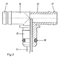
- the accumulator cell is equipped with an electrolyte circulation device (FIG. 3), which essentially consists of an air guide tube 11 and a T tube 12.
- the air duct 11 is a flexible, but dimensionally stable plastic part, for. B. made of polyethylene and has a length extending into the lower third of the cell vessel 1 and an outer diameter of less than 3.5 mm and a clear cross section of about 0.8 to 1.0 mm.
- the outside diameter must be so small that the air guide tube 11 can be inserted or inserted between the space 14 usually present between the edge of the positive or negative electrode plates 2, 3 and the end wall 13 of the cell vessel 1 during normal cell construction.
- the space 14 may differ depending on the cell type or size, it is generally less than 3.5 mm.
- An air guide tube 11 with an outer diameter of 3.0 mm and a clear cross section of 1.0 mm has proven to be particularly suitable.
- the T-tube 12 belonging to the electrolyte circulation device (FIG. 3) consists of a hard polyethylene which can be sprayed in a mold around the upper end of the air guide tube 11 so that it is embedded airtight in the transverse leg 15 of the T-tube 12 is.
- the two legs 16 of the T-tube 12 which run in one axis are provided with hose connections 17.
- the leg 15 enclosing the upper end of the air guide tube 11 is equipped with a sealing ring 18, which is opposite the pipe socket 8 of the cell cover 5 brings about an airtight seal.
- the electrolyte circulation device To attach the electrolyte circulation device, it is inserted with the air guide tube 11 through a diagnostic opening 7 of the cell cover 5 closing the cell. The air guide tube 11 is then pushed into the intermediate space 14 from above and finally fastened in the cover 5 by pressing legs 15 into the pipe socket 8.
- the electrolyte circulation device can optionally be inserted into the + or - side diagnosis opening 7 of the cell cover 5.
- Fig. 1 also shows that the air can escape through the centrally located plug 10.
Landscapes
- Chemical & Material Sciences (AREA)
- Chemical Kinetics & Catalysis (AREA)
- Electrochemistry (AREA)
- General Chemical & Material Sciences (AREA)
- Hybrid Cells (AREA)
Abstract
Description
- Die Erfindung betrifft eine Elektrolytumwälzeinrichtung für Bleiakkumulatorenzellen, bestehend aus einem Luftleitrohr, das neben der Gefäßwand angeordnet ist, bis in den unteren Bereich des Zellengefäßes ragt und mit seinem oberen Ende an ein aus Kunststoff bestehendes T-Rohr anschließt, dessen einer Schenkel durch den Zellendeckel führt und dessen beide anderen Schenkel Schlauchanschlüsse bilden.
- Um den Elektrolyt in den Zellen eines Bleiakkumulators zu homogenisieren und dadurch die Eigenschaften des Bleiakkumulators zu verbessern, ist eine Umwälzung des Elektrolyten bekannt. Die hierfür üblicherweise verwendete Umwälzeinrichtung besteht aus einem sehr steifen Luftleitrohr aus Kunststoff, dessen Durchmesser so groß ist, daß zur Anordnung zwischen der Stirnwand des Zellengefäßes und dem Plattensatz ein besonderer Raum dadurch gebildet werden muß, daß eine gesondert herzustellende positive Elektrodenplatte (Panzerplatte) eingesetzt ist, die ein Röhrchen weniger hat, also entsprechend kürzer ist. Das Luftleitrohr ist durch eine Öffnung im Zellendeckel hindurchgeführt und kann mit diesem durch Verkleben, Verschweißen oder durch Dichtungselemente luftdicht verbunden werden. Dem Anschluß an eine Druckluftleitung dient meist ein am Kopfende des Luftleitrohrs oder der Dekkelführung zugeordnetes T-Rohr, dessen zwei in einer Achse verlaufenden Schenkel Teil einer die Zellen einer Batterie verbindenden Verteilerleitung darstellen, während der querverlaufende Schenkel mit dem Luftleitrohr verbunden ist. Um bei einer Vielzahl von Zellen, die an eine solche Verteilerleitung angeschlossen sind, eine gleichgroße Luftmenge durch die einzelnen Zellen durchströmen zu lassen, ist am Kopfende des Luftleitrohres bzw. an der Deckeldurchführung in der Regel ein Drosselorgan o.dgl. angeordnet. Diese Ausführung hat zahlreiche Nachteile. Die Entfernung eines Röhrchens am Rand der positiven Elektrodenplatte beeinträchtigt die Entladekapazität. Bei der Montage ist ein sehr beschwerlicher lagerichtiger Einbau des Plattensatzes erforderlich, um das an einer bestimmten Stelle des Zellendeckels angebrachte steife Luftleitrohr einführen zu können. Weiterhin bereitet die dauerhaft luftdichte Abdichtung zwischen dem querverlaufenden Schenkel des T-Rohres und dem Luftleitrohr Schwierigkeiten und erfordert in der Regel aufwendige Kontrollmaßnahmen. Schließlich ist die Anordnung eines Drosselorgans in Form einer Verengung des Durchflußquerschnittes oder eines schraubenartigen Einsatzes umständlich, sehr aufwendig und fehleranfällig. Diese Nachteile entstehen auch bei der in DE-G 92 11 814.3 beschriebenen Einrichtung, bei der die positive Elektrodenplatte ein Röhrchen weniger hat, um Platz für ein Führungsrohr von etwa gleichem Durchmesser zu schaffen, das fest in der Zelle angeordnet ist und welches der Führung des elastischen Schlauches dient.
- Zur Vermeidung dieser Nachteile sieht die Erfindung eine dem Kennzeichen des Anspruches 1 entsprechende Ausbildung vor.
- Das Luftleitrohr hat einerseits einen so kleinen Außendurchmesser, daß es zwischen die Stirnwand des Zellengefäßes und den eingebauten Plattensatz schiebbar ist, ohne daß am Rand einer positiven Elektrodenplatte ein Röhrchen fehlt. Die Zelle weist daher ihre volle Entladekapazität auf. Da das Luftleitrohr ohne zu knicken biegsam ist, kann es bei der Montage leicht in einen der vorhandenen Freiräume zwischen Zellenstirnwand und Plattensatz eingeschoben werden, ohne daß spezielle Anforderungen an Aufbau und Lage des Plattensatzes bestehen. Weiterhin bilden das Luftleitrohr und das T-Rohr eine Baueinheit mit einer völligen Abdichtung. Da für die Unterbringung des Luftleitrohres kein besonderer Raum geschaffen werden muß, kann die Elektrolytumwälzeinrichtung auch nachträglich bei Zellen eingesetzt werden, die nicht für diesen Zweck vorbereitet wurden.
- Vorzugsweise beträgt der lichte Querschnitt des Luftrohres nur etwa 0,8 bis 1,0 mm, um die für eine gleichgroße Luftmenge erforderliche Drosselung zu erzielen. Der Einbau eines besonderen Drosselorgans kann daher entfallen. Ein besonders einfacher Zusammenbau läßt sich dadurch erzielen, daß der durch den Zellendeckel führende Schenkel des T-Rohrs mittels eines Dichtungsringes abdichtend in eine Diagnoseöffnung des Zellendeckels steckbar ist. Das Luftleitrohr und das T-Rohr bilden eine vorgefertigte Baueinheit, die durch einfaches Einstecken in einer Diagnoseoffnung des Zellendeckels anbringbar ist, so daß ein größerer Montageaufwand entfällt.
- Der Gegenstand der Erfindung ist in der Zeichnung dargestellt; es zeigt
- Fig. 1
- eine mit einer Elektrolytumwälzeinrichtung ausgerüstete Bleiakkumulatorenzelle in einem Längsschnitt,
- Fig. 2
- den Gegenstand der Fig. 1 in einer Draufsicht auf den Zellendeckel und
- Fig. 3
- das Kopfende der in Fig. 1 gezeigten Elektrolytumwälzeinrichtung in einer seitlichen Ansicht, teilweise geschnitten und in einem vergrößerten Maßstab.
- Die in Fig. 1 dargestellte Zelle eines Bleiakkumulators besteht aus einem Zellengefäß 1, in dem ein positive und negative Elektrodenplatten 2,3 aufweisender Plattensatz 4 angeordnet ist und das im Betriebszustand verdünnte Schwefelsäure als Elektrolyt enthält. Ein auf den Rand des Zellengefäßes 1 angeordneter Zellendeckel 5 ist mit zwei Polanschlüssen 6 und zwei Diagnoseöffnungen 7 versehen. An die Diagnoseöffnungen 7 schließt sich ein nach innen ragender Rohrstutzen 8 an. Die Diagnoseöffnungen 7 sind zunächst durch ein beim Spritzgießen des Zellendeckels 5 angeformtes Plättchen 9 verschlossen, das bei Bedarf ausgestoßen werden kann (vgl. Fig. 2).
- Die Akkumulatorenzelle ist mit einer Elektrolytumwälzeinrichtung (Fig. 3) ausgerüstet, die im wesentlichen aus einem Luftleitrohr 11 und einem T-Rohr 12 besteht. Das Luftleitrohr 11 ist ein flexibles, jedoch formstabiles Kunststoffteil, z. B. aus Polyethylen und hat eine bis in das untere Drittel des Zellengefäßes 1 reichende Länge sowie einen Außendurchmesser von kleiner als 3,5 mm und einen lichten Querschnitt von etwa 0,8 bis 1,0 mm. Der Außendurchmesser muß so klein sein, daß das Luftleitrohr 11 zwischen den bei normalem Zellenaufbau zwischen den Rand der positiven oder negativen Elektrodenplatten 2,3 und der Stirnwand 13 des Zellengefäßes 1 üblicherweise vorhandenen Zwischenraum 14 einschiebbar bzw. einsteckbar ist. Wenngleich der Zwischenraum 14 je nach der Zellentype bzw. -größe unterschiedlich sein kann, liegt er in der Regel unter 3,5 mm. Ein Luftleitrohr 11 mit einem Außendurchmesser von 3,0 mm und einem lichten Querschnitt von 1,0 mm hat sich als besonders geeignet erwiesen.
- Das der Elektrolytumwälzeinrichtung (Fig. 3) zugehörige T-Rohr 12 besteht aus einem harten Polyethylen, das sich in einer Spritzform um das obere Ende des Luftleitrohres 11 herum spritzen läßt, so daß dieses luftdicht in den querverlaufenden Schenkel 15 des T-Rohres 12 eingebettet ist. Die beiden in einer Achse verlaufenden Schenkel 16 des T-Rohres 12 sind mit Schlauchanschlüssen 17 versehen. Der das obere Ende des Luftleitrohres 11 einfassende Schenkel 15 ist mit einem Dichtungsring 18 ausgestattet, der gegenüber dem Rohrstutzen 8 des Zellendeckels 5 eine luftdichte Abdichtung herbeiführt.
- Zur Anbringung der Elektrolytumwälzeinrichtung wird diese mit dem Luftleitrohr 11 durch eine Diagnoseöffnung 7 des die Zelle verschließenden Zellendeckels 5 gesteckt. Sodann wird das Luftleitrohr 11 von oben in den Zwischenraum 14 geschoben und schließlich durch Einpressen von Schenkeln 15 in den Rohrstutzen 8 im Deckel 5 befestigt.
- Wie in Fig. 1 angedeutet ist, kann die Elektrolytumwälzeinrichtung wahlweise in die + oder - seitige Diagnoseöffnung 7 des Zellendeckels 5 eingesteckt werden. Fig. 1 zeigt ferner, daß die Luft über den zentral angeordneten Stopfen 10 entweichen kann.
-
- 1
- Zellengefäß
- 2
- positive Elektrodenplatten
- 3
- negative Elektrodenplatten
- 4
- Plattensatz
- 5
- Zellendeckel
- 6
- Polanschlüsse
- 7
- Diagnoseöffnungen
- 8
- Rohrstutzen
- 9
- Plättchen
- 10
- Stopfen
- 11
- Luftleitrohr
- 12
- T-Rohr
- 13
- Stirnwand
- 14
- Zwischenraum
- 15
- querverlaufende Schenkel von 12
- 16
- Schenkel
- 17
- Schlauchanschlüsse
- 18
- Dichtungsring
Claims (3)
- Elektrolytumwälzeinrichtung für Bleiakkumulatorenzellen, bestehend aus einem Luftleitrohr, das neben der Gefäßwand angeordnet ist, bis in das untere Drittel des Zellengefäßes ragt und mit seinem oberen Ende an ein aus Kunststoff bestehendes T-Rohr anschließt, dessen einer Schenkel durch den Zellendeckel führt und dessen beide anderen Schenkel Schlauchanschlüsse bilden, dadurch gekennzeichnet, daß das aus einem flexiblen und formstabilen Kunststoff bestehende Luftleitrohr (11) einen Außendurchmesser kleiner als 3,5 mm hat, mit seinem oberen Ende bei der im Spritzgieß- oder Spritzpreßverfahren erfolgenden Fertigung des T-Rohres in den durch den Zellendeckel (5) führenden Schenkel (15) eingebettet ist und zwischen den Plattensatz (4) und der Stirnwand (13) des Zellengefäßes (1) eingeschoben ist.
- Elektrolytumwälzeinrichtung nach Anspruch 1, dadurch gekennzeichnet, daß der lichte Querschnitt des Luftleitrohres (11) etwa 0,8 bis 1,0 mm beträgt.
- Elektrolytumwälzeinrichtung nach Anspruch 1 oder 2, dadurch gekennzeichnet, daß der durch den Zellendeckel (5) führende Schenkel (15) des T-Rohres (12) mittels eines Dichtungsringes (18) abdichtend wahlweise in eine der vorhandenen Diagnoseöffnungen (7) des Zellendeckels (5) steckbar ist.
Applications Claiming Priority (2)
| Application Number | Priority Date | Filing Date | Title |
|---|---|---|---|
| DE4311400 | 1993-04-07 | ||
| DE4311400A DE4311400C1 (de) | 1993-04-07 | 1993-04-07 | Elektrolytumwälzeinrichtung für Bleiakkumulatorenzellen |
Publications (3)
| Publication Number | Publication Date |
|---|---|
| EP0620605A2 true EP0620605A2 (de) | 1994-10-19 |
| EP0620605A3 EP0620605A3 (de) | 1994-12-21 |
| EP0620605B1 EP0620605B1 (de) | 1996-10-30 |
Family
ID=6484942
Family Applications (1)
| Application Number | Title | Priority Date | Filing Date |
|---|---|---|---|
| EP94200063A Revoked EP0620605B1 (de) | 1993-04-07 | 1994-01-13 | Bleiakumulator und Verwendung einer Elektrolytumwälzeinrichtung für Bleiakkumulatorenzellen |
Country Status (2)
| Country | Link |
|---|---|
| EP (1) | EP0620605B1 (de) |
| DE (1) | DE4311400C1 (de) |
Cited By (1)
| Publication number | Priority date | Publication date | Assignee | Title |
|---|---|---|---|---|
| EP1494301A3 (de) * | 2003-06-24 | 2006-01-18 | HAWKER GmbH | Batterie für Fahrzeuge |
Citations (1)
| Publication number | Priority date | Publication date | Assignee | Title |
|---|---|---|---|---|
| DE9211814U1 (de) | 1992-09-02 | 1992-12-03 | Accumulatorenwerke Hoppecke Carl Zoellner & Sohn GmbH & Co KG, 5790 Brilon | Vorrichtung zur Einführung eines Luftstromes in Zellen eines Akkumulators |
Family Cites Families (5)
| Publication number | Priority date | Publication date | Assignee | Title |
|---|---|---|---|---|
| US2584117A (en) * | 1949-12-28 | 1952-02-05 | Babcock & Wilcox Co | Circulation of cell electrolyte |
| IN150056B (de) * | 1977-09-12 | 1982-07-10 | Tudor Ab | |
| JPS5650060A (en) * | 1979-09-28 | 1981-05-07 | Shin Kobe Electric Mach Co Ltd | Formation with lead storage battery |
| US4693947A (en) * | 1986-04-21 | 1987-09-15 | The United States Of America As Represented By The United States Department Of Energy | System for agitating the acid in a lead-acid battery |
| JPH0230059A (ja) * | 1988-07-20 | 1990-01-31 | Japan Storage Battery Co Ltd | 印刷版用アルミニウム支持体の電解処理方法 |
-
1993
- 1993-04-07 DE DE4311400A patent/DE4311400C1/de not_active Expired - Fee Related
-
1994
- 1994-01-13 EP EP94200063A patent/EP0620605B1/de not_active Revoked
Patent Citations (1)
| Publication number | Priority date | Publication date | Assignee | Title |
|---|---|---|---|---|
| DE9211814U1 (de) | 1992-09-02 | 1992-12-03 | Accumulatorenwerke Hoppecke Carl Zoellner & Sohn GmbH & Co KG, 5790 Brilon | Vorrichtung zur Einführung eines Luftstromes in Zellen eines Akkumulators |
Cited By (1)
| Publication number | Priority date | Publication date | Assignee | Title |
|---|---|---|---|---|
| EP1494301A3 (de) * | 2003-06-24 | 2006-01-18 | HAWKER GmbH | Batterie für Fahrzeuge |
Also Published As
| Publication number | Publication date |
|---|---|
| EP0620605B1 (de) | 1996-10-30 |
| EP0620605A3 (de) | 1994-12-21 |
| DE4311400C1 (de) | 1994-05-11 |
Similar Documents
| Publication | Publication Date | Title |
|---|---|---|
| DE202012013316U1 (de) | Kabelkontaktierungswitterungsschutz | |
| DE19526197A1 (de) | Dachanordnung mit Planen und einer Mehrzahl die Planen zwischen sich aufnehmender Gitterträger sowie Gitterträger für eine derartige Dachanordnung | |
| DE8519055U1 (de) | Rückhalteklappe für Staubsauger | |
| EP0620605A2 (de) | Bleiakumulator und Verwendung einer Elektrolytumwälzeinrichtung für Bleiakkumulatorenzellen | |
| DE3312434A1 (de) | Staubsauger mit einem saugschlauch und einer steuervorrichtung | |
| DE3241677C1 (de) | Betaetigungsaufsatz fuer einen Druck-Zugschalter | |
| DE2018447B2 (de) | Sprühelektroden in Elektroabscheidern | |
| DE2904320C2 (de) | Mauerkasten zum Anschluß an das Ende eines flachen Lüftungskanals einer Dunstabzugshaube | |
| DE8626976U1 (de) | Vorrichtung zur Verbindung von Schläuchen mit Anschluß-Stutzen | |
| DE2347939C3 (de) | Kuppeiförmige Überdachung für runde Schwimmbecken | |
| DE1440082A1 (de) | Wetterschutzeinrichtung fuer Kabelkupplungen | |
| DE2734695C2 (de) | Bleistiftspitzer mit Spänebehälter und staubdicht aufsitzendem Verschlußstopfen | |
| DE2510250C3 (de) | Verbindungseinrichtung für Wetterluttenschüsse | |
| DE3341019A1 (de) | Dachabdeckplane fuer eine winterbauhalle | |
| DE2403869A1 (de) | Dichte wanddurchfuehrung von kabeln, leitungen o.dgl. | |
| DE960915C (de) | Aus Trockengleichrichterelementen aufgebauter Modulator | |
| DE19904221A1 (de) | Modulares Regenrinnensystem mit Reißverschlußmontage | |
| DE102007028936A1 (de) | Gehäuse mit Erweiterungszelt | |
| DE2626906B2 (de) | Niederspaiuiungs-Kabelabgriff zum Verbinden der Leiter eines Hauptkabels mit den Leitern eines Abzweigkabels | |
| CH610035A5 (en) | Inspection pipe | |
| DE890364C (de) | Huelle zur feuchtigkeitsdichten Einfuehrung der in Buendel aufgeteilten Adern vieladriger Kabel in Geraete | |
| DE513272C (de) | Lufteinlassvorrichtung fuer Lueftungsanlagen | |
| AT200199B (de) | Batterie, insbesondere Kraftfahrzeugbatterie | |
| DE2212026A1 (de) | Elektrische sammlerbatterie | |
| DE1939158U (de) | Polverbinder fuer elektrische sammler. |
Legal Events
| Date | Code | Title | Description |
|---|---|---|---|
| PUAI | Public reference made under article 153(3) epc to a published international application that has entered the european phase |
Free format text: ORIGINAL CODE: 0009012 |
|
| AK | Designated contracting states |
Kind code of ref document: A2 Designated state(s): FR GB IT NL |
|
| PUAL | Search report despatched |
Free format text: ORIGINAL CODE: 0009013 |
|
| AK | Designated contracting states |
Kind code of ref document: A3 Designated state(s): FR GB IT NL |
|
| 17P | Request for examination filed |
Effective date: 19941115 |
|
| 17Q | First examination report despatched |
Effective date: 19950920 |
|
| GRAG | Despatch of communication of intention to grant |
Free format text: ORIGINAL CODE: EPIDOS AGRA |
|
| GRAH | Despatch of communication of intention to grant a patent |
Free format text: ORIGINAL CODE: EPIDOS IGRA |
|
| GRAH | Despatch of communication of intention to grant a patent |
Free format text: ORIGINAL CODE: EPIDOS IGRA |
|
| ITF | It: translation for a ep patent filed | ||
| GRAH | Despatch of communication of intention to grant a patent |
Free format text: ORIGINAL CODE: EPIDOS IGRA |
|
| GRAA | (expected) grant |
Free format text: ORIGINAL CODE: 0009210 |
|
| AK | Designated contracting states |
Kind code of ref document: B1 Designated state(s): FR GB IT NL |
|
| GBT | Gb: translation of ep patent filed (gb section 77(6)(a)/1977) |
Effective date: 19961030 |
|
| ET | Fr: translation filed | ||
| PLBQ | Unpublished change to opponent data |
Free format text: ORIGINAL CODE: EPIDOS OPPO |
|
| PLBI | Opposition filed |
Free format text: ORIGINAL CODE: 0009260 |
|
| 26 | Opposition filed |
Opponent name: VHB INDUSTRIEBATTERIEN GMBH Effective date: 19970603 |
|
| PLBF | Reply of patent proprietor to notice(s) of opposition |
Free format text: ORIGINAL CODE: EPIDOS OBSO |
|
| NLR1 | Nl: opposition has been filed with the epo |
Opponent name: VHB INDUSTRIEBATTERIEN GMBH |
|
| PLBF | Reply of patent proprietor to notice(s) of opposition |
Free format text: ORIGINAL CODE: EPIDOS OBSO |
|
| PLBO | Opposition rejected |
Free format text: ORIGINAL CODE: EPIDOS REJO |
|
| APAC | Appeal dossier modified |
Free format text: ORIGINAL CODE: EPIDOS NOAPO |
|
| APAE | Appeal reference modified |
Free format text: ORIGINAL CODE: EPIDOS REFNO |
|
| APAC | Appeal dossier modified |
Free format text: ORIGINAL CODE: EPIDOS NOAPO |
|
| PLBQ | Unpublished change to opponent data |
Free format text: ORIGINAL CODE: EPIDOS OPPO |
|
| PLAB | Opposition data, opponent's data or that of the opponent's representative modified |
Free format text: ORIGINAL CODE: 0009299OPPO |
|
| REG | Reference to a national code |
Ref country code: GB Ref legal event code: IF02 |
|
| R26 | Opposition filed (corrected) |
Opponent name: HAWKER GMBH Effective date: 19970603 |
|
| APAC | Appeal dossier modified |
Free format text: ORIGINAL CODE: EPIDOS NOAPO |
|
| NLR1 | Nl: opposition has been filed with the epo |
Opponent name: HAWKER GMBH |
|
| PG25 | Lapsed in a contracting state [announced via postgrant information from national office to epo] |
Ref country code: IT Free format text: LAPSE BECAUSE OF NON-PAYMENT OF DUE FEES;WARNING: LAPSES OF ITALIAN PATENTS WITH EFFECTIVE DATE BEFORE 2007 MAY HAVE OCCURRED AT ANY TIME BEFORE 2007. THE CORRECT EFFECTIVE DATE MAY BE DIFFERENT FROM THE ONE RECORDED. Effective date: 20050113 |
|
| PLAG | Information modified related to despatch of communication that opposition is rejected |
Free format text: ORIGINAL CODE: EPIDOSCREJ1 |
|
| APAH | Appeal reference modified |
Free format text: ORIGINAL CODE: EPIDOSCREFNO |
|
| APAH | Appeal reference modified |
Free format text: ORIGINAL CODE: EPIDOSCREFNO |
|
| APBM | Appeal reference recorded |
Free format text: ORIGINAL CODE: EPIDOSNREFNO |
|
| APBP | Date of receipt of notice of appeal recorded |
Free format text: ORIGINAL CODE: EPIDOSNNOA2O |
|
| APBQ | Date of receipt of statement of grounds of appeal recorded |
Free format text: ORIGINAL CODE: EPIDOSNNOA3O |
|
| APAH | Appeal reference modified |
Free format text: ORIGINAL CODE: EPIDOSCREFNO |
|
| PGFP | Annual fee paid to national office [announced via postgrant information from national office to epo] |
Ref country code: NL Payment date: 20070117 Year of fee payment: 14 |
|
| PGFP | Annual fee paid to national office [announced via postgrant information from national office to epo] |
Ref country code: GB Payment date: 20070123 Year of fee payment: 14 |
|
| APBU | Appeal procedure closed |
Free format text: ORIGINAL CODE: EPIDOSNNOA9O |
|
| RDAF | Communication despatched that patent is revoked |
Free format text: ORIGINAL CODE: EPIDOSNREV1 |
|
| RDAG | Patent revoked |
Free format text: ORIGINAL CODE: 0009271 |
|
| STAA | Information on the status of an ep patent application or granted ep patent |
Free format text: STATUS: PATENT REVOKED |
|
| 27W | Patent revoked |
Effective date: 20071211 |
|
| GBPR | Gb: patent revoked under art. 102 of the ep convention designating the uk as contracting state |
Free format text: 20071211 |
|
| PGFP | Annual fee paid to national office [announced via postgrant information from national office to epo] |
Ref country code: IT Payment date: 20070504 Year of fee payment: 14 Ref country code: FR Payment date: 20070118 Year of fee payment: 14 |
|
| NLR2 | Nl: decision of opposition |
Effective date: 20071211 |