EP0619476B1 - Vorrichtung zur Detektion einer Flüssigkeitphasengrenze in einem lichtdurchlässigen Messrohr - Google Patents
Vorrichtung zur Detektion einer Flüssigkeitphasengrenze in einem lichtdurchlässigen Messrohr Download PDFInfo
- Publication number
- EP0619476B1 EP0619476B1 EP93119837A EP93119837A EP0619476B1 EP 0619476 B1 EP0619476 B1 EP 0619476B1 EP 93119837 A EP93119837 A EP 93119837A EP 93119837 A EP93119837 A EP 93119837A EP 0619476 B1 EP0619476 B1 EP 0619476B1
- Authority
- EP
- European Patent Office
- Prior art keywords
- liquid
- measuring tube
- light
- phase boundary
- fluid
- Prior art date
- Legal status (The legal status is an assumption and is not a legal conclusion. Google has not performed a legal analysis and makes no representation as to the accuracy of the status listed.)
- Expired - Lifetime
Links
Images


Classifications
-
- G—PHYSICS
- G01—MEASURING; TESTING
- G01F—MEASURING VOLUME, VOLUME FLOW, MASS FLOW OR LIQUID LEVEL; METERING BY VOLUME
- G01F23/00—Indicating or measuring liquid level or level of fluent solid material, e.g. indicating in terms of volume or indicating by means of an alarm
- G01F23/22—Indicating or measuring liquid level or level of fluent solid material, e.g. indicating in terms of volume or indicating by means of an alarm by measuring physical variables, other than linear dimensions, pressure or weight, dependent on the level to be measured, e.g. by difference of heat transfer of steam or water
- G01F23/28—Indicating or measuring liquid level or level of fluent solid material, e.g. indicating in terms of volume or indicating by means of an alarm by measuring physical variables, other than linear dimensions, pressure or weight, dependent on the level to be measured, e.g. by difference of heat transfer of steam or water by measuring the variations of parameters of electromagnetic or acoustic waves applied directly to the liquid or fluent solid material
- G01F23/284—Electromagnetic waves
- G01F23/292—Light, e.g. infrared or ultraviolet
- G01F23/2921—Light, e.g. infrared or ultraviolet for discrete levels
- G01F23/2922—Light, e.g. infrared or ultraviolet for discrete levels with light-conducting sensing elements, e.g. prisms
- G01F23/2925—Light, e.g. infrared or ultraviolet for discrete levels with light-conducting sensing elements, e.g. prisms using electrical detecting means
- G01F23/2927—Light, e.g. infrared or ultraviolet for discrete levels with light-conducting sensing elements, e.g. prisms using electrical detecting means for several discrete levels, e.g. with more than one light-conducting sensing element
-
- G—PHYSICS
- G01—MEASURING; TESTING
- G01N—INVESTIGATING OR ANALYSING MATERIALS BY DETERMINING THEIR CHEMICAL OR PHYSICAL PROPERTIES
- G01N35/00—Automatic analysis not limited to methods or materials provided for in any single one of groups G01N1/00 - G01N33/00; Handling materials therefor
- G01N35/0099—Automatic analysis not limited to methods or materials provided for in any single one of groups G01N1/00 - G01N33/00; Handling materials therefor comprising robots or similar manipulators
Definitions
- the invention relates to a Automatic device exact dosing of small amounts of liquid in a medical Analysis device comprising a device for detection a liquid phase boundary in a translucent Measuring tube.
- liquid phase boundary is every interface between a liquid and one in phase contact to this standing optically distinguishable phase, which can be gaseous, liquid or solid.
- Devices are mostly used for detection of the level of a liquid in an upright position standing measuring tube, hereinafter referred to as a riser becomes. They are used in specialist circles according to a English expression also as LLD (Liquid Level Detector).
- LLD Liquid Level Detector
- the Invention for use cases in connection with devices for the analysis of body fluids (especially blood and Urine). It is particularly about the detection of Liquid phase boundary of samples or liquid reagents.
- the probe mostly is also a pipette tip through which a reagent or sample liquid supplied or aspirated can be.
- a liquid detector when immersed - possibly even shortly before immersion - generates a signal in the liquid.
- This Principles known, for example, on the Determination of electrical resistance or electrical Capacity between two at the tip of the pipette attached electrodes based.
- optical principles for such applications have been discussed (European patent 0250671). With these The method gives the position of the probe or pipette a measure of the height when immersed in the liquid of the liquid level.
- the invention is directed in particular, but not exclusively, on the determination of the liquid phase boundary in a dosing device with a rising tube closed at the top.
- Optical measuring principles have been used for such applications proposed in which the riser pipe with a minimum a lighting device having a light source is illuminated with a light receiving device at least one light receiver is provided, the one Part of the through the riser pipe or the contained therein Liquid receiving light receives and in from whose location-dependent intensity distribution dependent converts electrical signals.
- the signals of the light receiving device become an electronic evaluation device fed to the desired information about the level of the liquid level in the Derive the riser pipe.
- the liquid-filled riser pipe serves as a lens to apply a narrow band of light to one of the Light source (related to the riser) opposite Focus area. It is important that Riser pipe has a certain (cylindrical) shape and the geometrical conditions of focusing exactly adhered to become.
- the light receiving device a Plurality of light receivers in the form of photocells, Photoresistors, photodiodes, phototransistors or The like, each opposite a light transmitter are arranged parallel to the riser pipe, so that they have a multitude of densely arranged one above the other Form light barriers.
- This arrangement allows a comfortable level detection, but can with regard the resolution and precision of the height determination meet only minor requirements. It will be with one Working distance of the photosensitive elements of 1 mm and a precision of volume determination in the Rise tube of approximately 100 ⁇ l reached. This results in, that a relatively thick riser pipe with an inner diameter of about 5 mm was used.
- an inner diameter of, for example, less than 1 mm is the one used in the European patent application on the different focus of the filled and the principle of the empty measuring tube is not suitable.
- German patent application 36 05 403 Device based the detection of the liquid level insist that a continuous Transition of the measured light intensity in the range of Liquid level is reached. This is done in parallel linear light source running to the riser in conjunction with a number of immediately detectors provided to the riser. It will viewed as essential to make a difference regarding the detected light intensity between the liquid-filled and the gas-filled area of the Riser pipe. This difference becomes apparent ensured that either the liquid was colored or (as in the previously described devices) the cylindrical lens effect when the light passes through the riser pipe is used.
- JP-A-60 086 439 is an apparatus for Measure a given sample volume known for a serum analysis. It is suggested, parallel rays of light through the Let the measuring tube pass through and Light guiding elements on a one-dimensional Arrangement of photosensitive elements to steer. An exact dosage of small amounts of liquid is not possible with it.
- the invention is directed according to a first main aspect of a device for Detection of a liquid phase boundary in a translucent Measuring tube with a lighting device with at least one light source for illuminating the Measuring tube, a light receiving device with at least a light receiver that passes through the measuring tube Light receives and depends on its location Intensity distribution dependent electrical signals converts and an evaluation unit for processing the Signals from the light receiving device for information about the position of the liquid phase boundary in the Measuring tube in which the lighting device for steady illumination of a detection section of the Measuring tube is formed and the light receiving device an optical imaging system for imaging the Detection section in an image plane and a row closely adjacent photosensitive elements in the Has image plane.
- the photosensitive elements in the image plane of the expediently serving as an optical imaging system Lenses are preferably a linear array of CCD elements (charged coupled devices).
- the distance of the photosensitive elements is preferably less than 50 ⁇ m.
- the position of a liquid phase boundary in a measuring tube with a very small diameter less than 1 mm, particularly preferably even less than 0.5 mm can be reliably and accurately detected.
- the invention enables the position determination of the Liquid phase boundary in such thin capillaries without moving parts. Because the liquid column in the measuring tube over a longer detection section is recorded with high resolution, it is also possible typical sources of error, such as air bubbles or contamination, using one of a microprocessor controlled Evaluation device carried out detection algorithm to eliminate.
- the illumination of the detection section must be steady in the sense that (unlike light barriers) none sudden changes in the spatial distribution of lighting intensity occurrence.
- Such steady lighting can be done by various known means achieve, for example with the help of an elongated (for example tubular), parallel to that Measuring tube running light source, a variety of parallel arranged close to the measuring tube Light sources or lighting optics that light corresponding to a simple light source (e.g. halogen lamp) expands.
- a simple light source e.g. halogen lamp
- the structure is relatively simple. There are not any Apertures, filters or shields required. It can extremely high accuracy and precision become. For example, with the invention in a capillary with an inner diameter of 0.2 mm and a distance of the CCD elements (pixels) of 25 ⁇ m volume differences of +/- 1 nl reliably detected.
- the system works without moving parts and without delay. It is possible to change the time Position of the phase boundary to be recorded precisely and for example to determine their speed of movement.
- the invention is directed to a device for automatic exact dosing of small amounts of liquid.
- Such devices are also called (automatic) Referred to as pipettors.
- You will be related with the analysis of body fluids, especially at corresponding analyzers, widely used to Samples and reagents from one vial to another Transfer vessel.
- the dosage of the liquid is based on the movement of a piston in one Precision tube.
- the piston is usually made by one Stepper motor driven, its movement over a Toothed belt is transferred to a spindle drive.
- This spindle drive moves a carriage that is usually firmly connected to the piston.
- the precision dosing with such a piston pump depending on the precision of the stepper motor and the accuracy the transmission elements (toothed belt, spindle drive).
- the invention provides an automatic pipettor with high accuracy, especially for dosing very small sample volumes to disposal. It has a phase boundary detection device ("Phase Boundary Detection Means, PBDM") through which a liquid phase boundary in a measuring tube automatically detected and a the position of the phase boundary in a detection section of the measuring tube electrical signal is generated.
- PBDM Phase Boundary Detection Means
- a liquid phase boundary in a measuring tube automatically detected and a the position of the phase boundary in a detection section of the measuring tube electrical signal is generated.
- PBDM Phase Boundary Detection Means
- AFTM Auxiliary fluid transfer device Means
- auxiliary fluid Auxiliary Fluid Supply Means, AFSM
- AFWM suction Auxiliary Fluid Withdrawl Means
- An electronic control unit is provided depending on the auxiliary fluid transfer device from that of the position of the liquid phase boundary to control the corresponding signal such that Suction or supply of auxiliary fluid to the measuring tube precisely defined amounts of liquid sucked in or be expelled.
- the detection device for the detection of the liquid phase boundary is designed according to claim 1. This can be done using a thin capillary tube can be used as a measuring tube, which immediately is immersed in the liquid, the Level of liquid with the LLD according to the invention at a relatively short distance is precisely determined over the suction opening. There the sample volume directly in the pipette tip serving capillary tube can be measured and therefore the aspirated volume is determined directly and immediately different conditions, like air pressure, Room temperature or viscosity of the liquid practically without influence on the dosing precision.
- the measuring tube can be used as a disposable Capillary be formed, which in an automatic Holder of the pipettor is used. This will the risk of transferring liquid residues to the each next metered volume of liquid ("Procrastination") completely avoided.
- Procrastination liquid residues to the each next metered volume of liquid
- the pipettor In connection with the pipettor according to the invention can be a LLD are used, the level of a Liquid in a riser tube closed at the top automatically detected and a resulting electrical Generates signal, which is fed to the control unit is used to suck and expel the liquid to control precisely.
- Known devices of this Art were mentioned in the introduction.
- the auxiliary fluid can be a gas or a liquid.
- a liquid can expediently with the help of a Piston pump supplied or extracted with precise control become. If the auxiliary liquid with the to be dosed Liquid immiscible can be at the phase boundary direct contact between the two liquids consist. You can also work with a miscible liquid between the auxiliary liquid and a gas bubble is sucked in. This Separation of two different liquids with the help a gas bubble is common in analysis technology. In in this case one of the phase boundaries between the dosing liquid or the auxiliary liquid and the Gas bubble detected.
- auxiliary fluid is a gas, in particular air and the measuring tube as Riser pipe runs essentially vertically.
- the phase boundary is the liquid level, which is the liquid column in the riser pipe from the one above Separates gas space to which the gaseous auxiliary fluid is supplied or from which it is sucked off.
- a switching valve device which consists of a Multi-way valve or several individual valves exist can.
- there should be at least one shut-off valve i.e. a valve that quickly moves between an open and closed position changes) close to the upper end of the riser pipe.
- the automatic pipettor according to the invention is particularly suitable for the fully automatic pipetting of very small amounts of liquid (in the range between 20 nl and 20 ⁇ l, ie 2 x 10 -8 l to 2 x10 -5 l).
- a very high level of precision is achieved.
- the coefficient of variation (CV) is, for example, a maximum of 1% (ie 10 -10 l).
- a thin capillary with an inner diameter between 0.1 mm and 0.3 mm is used as the measuring tube, which is immersed directly in the liquid to be pipetted (ie the liquid transfer opening is a component of the measuring tube).
- the control of a metered amount of liquid by means of an optical LLD is from the German patent 35 15 890 known.
- the function differs in essential elements from the device described here.
- the liquid by means of a downstream of the measuring tube Injector spray nozzle sucked out of the measuring tube.
- Fast and low-drag dosing of a sequence perform different liquids like this is required for clinical analyzers.
- the function of the automatic pipettor according to the invention is practically not due to mechanical wear impaired. Changeover valves are subject to only a small number Wear that their function over a long life unaffected. Will be according to a preferred Embodiment a gas pump as a gas suction device and / or gas supply device used, is subject mechanical wear and tear, however is insignificant for the precision of the dosage. It can a simple and relatively inexpensive gas pump be used.
- the device according to the invention works with different ones Dosing liquids, especially blood, Serum and protein-containing reagent fluids perfectly, even if these differ in their composition,
- Viscosity and hydrophobicity differ significantly. Changes in liquids have practically no influence on the pipetting precision. Changes in environmental conditions (for Example temperature changes) can be in contrast to conventional pipettors relatively easily in the control algorithm taken into account and thereby eliminated become.
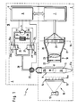
- the automatic pipettor 1 shown in FIG. 1 exists essentially from a detection device 2 for the detection of a liquid phase boundary 10 in the Detection section 8 of a measuring tube 9, and a Auxiliary fluid transfer device 16, to which a switching valve device 3 and a gas pump 4 heard.
- a electronic central unit 5 includes a control unit 6 for the gas pump 4 and the switching valve device 3 and an evaluation unit 7 for the detection device 2 a.
- the detection device 2 is in the case shown a liquid level detection device (LLD), i.e. the phase boundary 10 is the boundary between air and Liquid in a vertical riser 11 Measuring tube 9.
- LLD liquid level detection device
- the LLD is used to measure the height of the Liquid level 10 in the riser 11 automatically to detect.
- the riser 11 from a light source 12 via a light scattering device 13 illuminated with diffuse light.
- the light scattering device In the illustrated case, 13 is a focusing screen 14, whereby the riser pipe 11 on that facing away from the light source 12 Side of the focusing screen 14 and the focusing screen 14 and the riser 11 arranged approximately parallel to each other are.
- the light source 12 and the light scattering device form 13 a lighting device 15 for Illumination of the riser 11.
- a light receiving device 17 On the one opposite the lighting device 15 there is a light receiving device 17, which consists of an optical imaging system 18 for mapping the riser pipe into one Image plane 19 and one arranged in the image plane 19 Row 20 of photosensitive elements, which in the illustrated preferred case CCD elements (pixels) 21 are.
- the light source 12 can consist of one or more lamps, for example halogen lamps, tungsten lamps or the like consist.
- the light scattering device is preferred a screen 14 illuminated from the rear, however, the preferred diffuse in the context of the invention Illumination of the riser 11 also with, for example a diffusely reflecting surface, which is illuminated from the side in such a way that preferably no light from the light source directly on the riser 11 falls.
- a diffusely reflecting surface which is illuminated from the side in such a way that preferably no light from the light source directly on the riser 11 falls.
- the Riser pipe 11 facing surface which as a diffusion surface 14a can be referred to in uniform Distance (i.e. approximately parallel) to this.
- the riser pipe 11 is preferably a capillary with a Inner diameter of less than 1 mm, particularly preferred less than 0.5 mm. Its lower end is in Fluid connection with a liquid transfer port lla through which the liquid is sucked in and expelled can be. "Is in fluid communication (fluid communication) "is to be understood in such a way that the liquid transfer opening 11a - as shown - an opening of the riser 11 itself or by means of a Pipe or hose in indirect connection with the riser 11 can stand.
- the optical imaging system 18 suitably exists from an aperture 22 and one (only in the drawing lens (indicated as a lens) 23.
- the range of photosensitive elements may change also be part of a two-dimensional arrangement that not only parallel to the riser 11, but also extends perpendicular to it in the image plane 19. As sufficient and especially useful has a pure linear arrangement of the CCD pixels has been shown, with their spacing is less than 50 microns, preferably at most 25 microns.
- the Light source 12, the riser 11 and the row 20 of CCD pixel 21 in one plane With this arrangement (and Dosage of a clear liquid) provide CCD pixels, onto which the liquid-filled area of the capillary is mapped, a higher output signal than that Pixels on which the air-filled area of the capillary is imaged becomes.
- FIG. 2 shows a graphical representation A of the output signals the CCD pixel 21 depending on the location X of the capillary riser 11, which is shown on it.
- the output signal of the CCD line sensor was over a Interface transferred to a standard personal computer, which served as evaluation device 7.
- the assignment the CCD output signals for the values "capillary filled” or "capillary empty” was carried out with the help of a according to the set threshold.
- the interface should enable parallel processing of the data ensures the position of the liquid level in real time is.
- the graphs B, C, D of Figures 3 to 5 illustrate the dependence of the measurement signal on the Angular position of the light source 12 and the light scattering device 13. A supervision is shown in each case, the axis of the riser 11 is therefore perpendicular to Drawing level.
- Azimuth angle ⁇ (related to one to the riser 11 vertical plane) the difference of the Pixel output signals that the liquid-filled and correspond to the air-filled section of the riser 11.
- the measuring arrangement is designed so that the brightness of the liquid-filled section and the gas-filled section of the measuring section of the riser 11 clearly distinguish (as in Figure 2, 3 and 5), is the evaluation of the output signal of row 20 the photosensitive elements 21 particularly simple. How in general, it suffices to add a threshold value in this way place it about halfway between the output signals lies that of the filled or the empty capillary correspond. This allows a very good accuracy achieve without a high-precision adjustment of the Components is required. As from Figures 2 to 5 is shown schematically, the intensities change over relatively wide angular ranges only slightly.
- phase boundary detection device according to the invention (PBDM) is that exact localization even in such cases allows the phase boundary in which the brightness the areas of the measuring tube adjacent to the phase boundary does not differ, or differs only very slightly.
- FIG. 6 shows the signal of the CCD pixels in an experiment, in which the measuring section depicted on the CCDs 8 of a measuring tube 9 in successive partial areas Contains water (W), silane oil (O) and again water (W).
- W water
- O silane oil
- W water
- the oil does not mix with water, so that between form water / oil phase boundaries W / O and O / W, respectively.
- the measured output signals are preferably used the CCD pixel is first digital low-pass filtering subjected. Such methods, for example with the help of a Hamming, Blackman, or Hanning window function are known. They lead to smoothing the waveform. This will cause false ads a phase boundary due to random signal fluctuations avoided.
- the signal minimum can be found in the filtered signal curve again with the help of a limit value.
- a limit value is expediently a multiple of the statistical Fluctuation range of the pixel signals below the mean signal value of a defined neighborhood (for example 10 pixels).
- One below this intensity limit is called the phase boundary recognized.
- the automatic shown in Figure 1 includes Pipettor 1 next to the LLD 2 the switching valve device 3, the gas pump 4 and the associated control unit 6.
- the switching valve device 3 consists in the shown preferred embodiment from a quick shut-off valve 25 and two changeover valves 26 and 27.
- the valves 26, 27 each have a first side 26a, 27a a connection and on a second side 26b, 27b two connections, whereby by switching the Valve optionally a connection between the one connection the first side and one of the connectors of the second side is produced.
- the first page 26a of the Valve 26 is connected to the pressure side 4a of the gas pump 4, while the first side 27a of the valve 27 with the suction side 4b of the gas pump is connected.
- valves 26, 27 From the two ports on the second side of the valves 26, 27 are each connected to a Y line system 28, through that a connection to that of that Connection of the shut-off valve 25 facing away from the riser pipe 11 will be produced.
- the other connection of the second Page 26b, 27b of the valves 26,27 is with the outside air connected.
- the valves 26, 27 are switched synchronously so that in a first position (in the figure with shown by solid lines) the pressure side of the Gas pump 4 is connected to the shut-off valve 25 while in a second position (dashed in the figure shown) the suction side 4b with the shut-off valve 25 connected is.
- a bypass 29 with at least one Pressure relief valve 30 is provided.
- the changeover valves 26, 27 brought into the position shown in dashed lines, so that a negative pressure generated by the gas pump 4 is applied to the shut-off valve 25.
- this Valve connects to the gas space 11b of the Riser pipe 11 made above the liquid level 10.
- the liquid is sucked in and the liquid level 10 increases under the control of LLD 2.
- the valve control signal is from the control unit 6 depending on one of the Evaluation unit 7 generated electrical signal, which corresponds to the level of the liquid level 10, by comparison with a desired altitude corresponding setpoint is generated.
- the switching valve device 3 can, as the person skilled in the art is common to be constructed in a different way, for example using a four-way valve or by four one-way valves, which are switched synchronously, that at the desired time gas the gas space 11b is supplied or removed therefrom.
- phase boundary 10 is an interface between those located in the lower part of the measuring tube 9 Liquid column 32 and that in the gas space 11b air.
- a liquid instead of the gas (air) become.
- a liquid pump for example a piston pump
- a liquid reservoir Sucks in liquid or in it or deliver another container.
- Fluids gas or liquids
- the liquid to be dosed to suck into or to eject from the measuring tube 9 is the embodiment with a gas (in particular Air) particularly preferred because it is special is simple and every contact of the liquid to be dosed with another liquid.
- a gas in particular Air
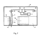
- the Lighting device 15 has a light-tight closed Housing in which the light source, not shown located. On the riser 11 facing Side of the lighting device 15 is the ground glass 14 attached.
- the light receiving device 17 is also including the imaging optical system 18 in housed in a common light-tight closed housing.
- the connecting lines between the gas pump 4, the changeover valves 25, 26, the pressure relief valve 30 and the solenoid valve 25 are formed by hoses.
- the riser pipe 11 is a very thin capillary attached to the frame 33 by means of a support part 34 is.
- the riser pipe 11 fixed. It can therefore occur during pipetting not be moved up and down. If such Movement is desired, it can be within the scope of the present Realize invention either by that Riser pipe 11 in a precisely predetermined and measurable manner and way is moving up and down and this movement by the evaluation unit 7 when calculating the level (and the resulting volume) in the riser is taken into account. There is a second possibility in using a fixed standpipe and on it lower end over a flexible hose one separately Movable pipetting needle with the liquid transfer opening to connect.
Landscapes
- Physics & Mathematics (AREA)
- Electromagnetism (AREA)
- General Physics & Mathematics (AREA)
- Thermal Sciences (AREA)
- Fluid Mechanics (AREA)
- Analytical Chemistry (AREA)
- General Health & Medical Sciences (AREA)
- Health & Medical Sciences (AREA)
- Life Sciences & Earth Sciences (AREA)
- Chemical & Material Sciences (AREA)
- Engineering & Computer Science (AREA)
- Biochemistry (AREA)
- Robotics (AREA)
- Immunology (AREA)
- Pathology (AREA)
- Automatic Analysis And Handling Materials Therefor (AREA)
- Investigating Or Analysing Materials By Optical Means (AREA)
- Measurement Of Levels Of Liquids Or Fluent Solid Materials (AREA)
- Length Measuring Devices By Optical Means (AREA)
- Sampling And Sample Adjustment (AREA)
Description
- Fig. 1
- Eine Prinzipdarstellung eines automatischen Pipettors mit Flüssigkeitsspiegeldetektionsvorrichtung;
- Fig. 2 bis Fig. 5
- Prinzipdarstellungen unterschiedlicher Anordnungen der Beleuchtungseinrichtung und der Lichtempfangseinrichtung bei einer erfindungsgemäßen Flüssigkeitsspiegeldetektionsvorrichtung;
- Fig. 6
- eine Meßkurve einer gemessenen Intensitätsverteilung in Abhängigkeit vom Ort des lichtempfindlichen Elementes in der Bildebene,
- Fig. 7
- eine praktische Ausführungsform einer Vorrichtung gemäß Fig. 1 in Seitenansicht.
Claims (15)
- Vorrichtung zum automatischen exakten Dosieren kleiner Flüssigkeitsmengen in einem medizinischen Analysegerät, umfassendeine Detektionsvorrichtung (2), mittels der eine Flüssigkeits-Phasengrenze (10) in einem lichtdurchlässigen Meßrohr (9) mit einer Kapillare mit einem Innendurchmesser von weniger als 1 mm, bevorzugt weniger als 0,5 mm automatisch detektiert und ein der Position der Phasengrenze (10) in einem Detektionsabschnitt (8) des Meßrohres (9) entsprechendes elektrisches Signal erzeugt wird,mit einer Beleuchtungseinrichtung (15) mit mindestens einer Lichtquelle (12) zur Beleuchtung des Meßrohres (9), einer Lichtempfangseinrichtung (17) mit mindestens einem Lichtempfänger, die durch das Meßrohr (9) hindurchtretendes Licht empfängt und in von dessen ortsabhängiger Intensitätsverteilung abhängige elektrische Signale umwandelt und einer Auswerteeinheit (7) zur Verarbeitung der Signale der Lichtempfangseinrichtung (17) zu einer Information über die Position der Flüssigkeits-Phasengrenze (10) in dem Meßrohr (9),wobei die Beleuchtungseinrichtung (15) zur stetigen Beleuchtung eines Detektionsabschnittes (8) des Meßrohres (9) ausgebildet ist unddie Lichtempfangseinrichtung (17) ein optisches Abbildungssystem (18) zur Abbildung des Detektionsabschnittes (8) in eine Bildebene (19) und eine Reihe (20) eng benachbarter lichtempfindlicher Elemente in der Bildebene aufweist,eine mit einem ersten Ende des Meßrohres (9) in Fluidverbindung stehende Flüssigkeitstransferöffnung (11a) zum Ansaugen und Ausstoßen von Flüssigkeit,eine mit einem zweiten Ende des Meßrohres (9) in Fluidverbindung stehende Hilfsfluid-Transfereinrichtung (16) zum präzise gesteuerten Zuführen und Absaugen eines gasförmigen oder flüssigen Hilfsfluids zu bzw. von dem Meßrohr undeine elektronische Steuereinheit (6), durch die die Hilfsfluid-Transfereinrichtung (16) in Abhängigkeit von dem der Position der Flüssigkeits-Phasengrenze (10) entsprechenden Signal derart ansteuerbar ist, daß durch Absaugen bzw. Zuführen von Hilfsfluid zu dem Meßrohr präzise definierte Flüssigkeitsmengen angesaugt bzw. ausgestoßen werden.
- Vorrichtung nach Anspruch 1, dadurch gekennzeichnet, daß die Auswerteeinheit (7) zur Detektion der Position der Flüssigkeits-Phasengrenze (10) in dem Detektionsabschnitt (8) des Meßrohres (9) mittels aus der ortsabhängigen Intensitätsverteilung der elektrischen Signale gewonnenen Informationen über den Signalverlauf der Signale der Lichtempfangseinrichtung (17) ausgebildet ist.
- Vorrichtung nach einem der vorhergehenden Ansprüche, dadurch gekennzeichnet, daß die Auswerteeinheit (7) Filtermittel zum Glätten des Signalverlaufs der Signale der Lichtempfangseinrichtung (17) mittels einer Tiefpaßfilterung umfaßt.
- Vorrichtung nach einem der vorhergehenden Ansprüche, insbesondere nach Anspruch 3, dadurch gekennzeichnet, daß die Auswerteeinheit (7) Differenzierungsmittel zum Differenzieren des Signalverlaufs der Signale der Lichtempfangseinrichtung (17) umfaßt.
- Vorrichtung nach einem der vorhergehenden Ansprüche, insbesondere nach Anspruch 4, dadurch gekennzeichnet, daß die Auswerteeinheit (7) Schwellwertmittel zum Erkennen der Flüssigkeits-Phasengrenze (10) aus dem Signalverlauf der Signale der Lichtempfangseinrichtung (17) mittels einer Schwellwertdetektion umfaßt.
- Vorrichtung nach einem der vorhergehenden Ansprüche, bei welcher die lichtempfindlichen Elemente CCD's sind.
- Vorrichtung nach einem der vorhergehenden Ansprüche, bei welcher der Abstand der lichtempfindlichen Elemente voneinander kleiner als 50 µm ist.
- Vorrichtung nach einem der vorhergehenden Ansprüche, bei welcher die Beleuchtungseinrichtung (15) eine Lichtstreueinrichtung (13) zur Beleuchtung des Detektionsabschnittes (8) des Meßrohres (9) mit diffusem Licht aufweist.
- Vorrichtung nach Anspruch 8, bei welcher die Lichtstreueinrichtung (13) eine etwa parallel zu dem Meßrohr (11) verlaufende Diffusionsfläche (14a) aufweist.
- Vorrichtung nach einem der Ansprüche 8 oder 9, bei welcher die Diffusionsfläche (14a) eine Mattscheibe (14) ist und die mindestens eine Lichtquelle (12) sich auf der von dem Meßrohr (11) abgewandten Seite der Mattscheibe (14) befindet.
- Vorrichtung nach einem der vorhergehenden Ansprüche, bei welcher das Hilfsfluid ein Gas, insbesondere Luft, das Meßrohr (9) ein Steigrohr (11) für die Flüssigkeit und die Phasengrenze (10) ein Flüssigkeitsspiegel ist, der eine Flüssigkeitssäule in dem Steigrohr (11) von einem darüber befindlichen Gasraum (11b) trennt, wobei das Gas dem Gasraum (11b) zugeführt bzw. von diesem abgeführt wird, um präzise definierte Flüssigkeitsmengen auszustoßen bzw. anzusaugen.
- Vorrichtung nach einem der vorhergehenden Ansprüche, bei welcher die Hilfsfluid-Transfereinrichtung eine Umschaltventileinrichtung (3) aufweist, welche mit einer Fluidabsaugeinrichtung und mit einer Fluidzufuhreinrichtung in Fluidverbindung steht.
- Vorrichtung nach den Ansprüchen 11 und 12, bei welcher die Umschaltventileinrichtung (3) ein dicht beim oberen Ende des Steigrohres (11) angeordnetes Absperrventil (25) einschließt.
- Vorrichtung nach einem der Ansprüche 11 bis 13, bei welcher eine Gaspumpe (4) als kombinierte Gasabsaugund Gaszufuhreinrichtung mittels Umschaltventilen (26,27) wahlweise mit ihrer Saugseite und mit ihrer Druckseite an das obere Ende des Steigrohres anschließbar ist.
- Vorrichtung nach einem der vorhergehenden Ansprüche, dadurch gekennzeichnet, daß das Meßrohr (9) zum Dosieren von Flüssigkeitsmengen von weniger als 20 µl ausgebildet ist.
Applications Claiming Priority (2)
| Application Number | Priority Date | Filing Date | Title |
|---|---|---|---|
| DE4243247 | 1992-12-19 | ||
| DE4243247 | 1992-12-19 |
Publications (2)
| Publication Number | Publication Date |
|---|---|
| EP0619476A1 EP0619476A1 (de) | 1994-10-12 |
| EP0619476B1 true EP0619476B1 (de) | 1999-09-22 |
Family
ID=6475952
Family Applications (1)
| Application Number | Title | Priority Date | Filing Date |
|---|---|---|---|
| EP93119837A Expired - Lifetime EP0619476B1 (de) | 1992-12-19 | 1993-12-09 | Vorrichtung zur Detektion einer Flüssigkeitphasengrenze in einem lichtdurchlässigen Messrohr |
Country Status (5)
| Country | Link |
|---|---|
| US (1) | US5463228A (de) |
| EP (1) | EP0619476B1 (de) |
| JP (1) | JP2651349B2 (de) |
| DE (1) | DE59309797D1 (de) |
| ES (1) | ES2137965T3 (de) |
Cited By (2)
| Publication number | Priority date | Publication date | Assignee | Title |
|---|---|---|---|---|
| DE102007003040A1 (de) * | 2007-01-20 | 2008-07-31 | Stratec Biomedical Systems Ag | Vorrichtung zur optischen Detektion eines Phasenübergangs oder dergleichen |
| LU103204B1 (en) | 2023-10-13 | 2025-04-22 | Stratec Se | Optical fluid verification for dispense volume evaluation |
Families Citing this family (63)
| Publication number | Priority date | Publication date | Assignee | Title |
|---|---|---|---|---|
| DE4331997A1 (de) * | 1993-09-21 | 1995-03-23 | Boehringer Mannheim Gmbh | Verfahren und System zur Mischung von Flüssigkeiten |
| DE69532920T2 (de) * | 1995-05-30 | 2005-04-14 | Ivek Corp. | Vorrichtung zur volumetrischen Abgabe von Flüssigkeiten |
| US5565977A (en) * | 1995-06-07 | 1996-10-15 | Baxter International Inc. | Systems and methods for identifying and controlling interfaces between blood components |
| CA2177658A1 (en) * | 1995-07-10 | 1997-01-11 | Kurukundi Ramesh Murthy | Volume detection apparatus and method |
| US6250130B1 (en) | 1995-07-10 | 2001-06-26 | Bayer Corporation | Method and apparatus for monitoring an aspirating and dispensing system |
| KR100454611B1 (ko) | 1996-10-30 | 2005-06-10 | 스미또모 가가꾸 고오교오 가부시끼가이샤 | 합성실험자동화시스템및분액처리장치와반응용기 |
| DE19817995C1 (de) * | 1998-04-22 | 1999-09-09 | Stoeckert Instr Gmbh | Vorrichtung zur Überwachung des Füllstands eines Blutreservoirs |
| US6235534B1 (en) * | 1998-04-27 | 2001-05-22 | Ronald Frederich Brookes | Incremental absorbance scanning of liquid in dispensing tips |
| US6343614B1 (en) * | 1998-07-01 | 2002-02-05 | Deka Products Limited Partnership | System for measuring change in fluid flow rate within a line |
| US6041801A (en) * | 1998-07-01 | 2000-03-28 | Deka Products Limited Partnership | System and method for measuring when fluid has stopped flowing within a line |
| DE50010939D1 (de) * | 2000-04-28 | 2005-09-15 | Fraunhofer Ges Forschung | Flüssigkeitsreservoir mit füllstandsmessung und dosiersystem, entnahmesystem sowie kombiniertes dosier/entnahmesystem |
| DE10041014A1 (de) * | 2000-08-22 | 2002-03-07 | Merck Patent Gmbh | Bestimmung von Flußraten |
| JP3602063B2 (ja) * | 2001-03-23 | 2004-12-15 | 株式会社日立製作所 | 検出対象の寸法を自動的に検出する装置及びそれを用いた自動分析装置 |
| WO2002101337A1 (en) * | 2001-06-12 | 2002-12-19 | Naoyuki Omatoi | Liquid level detecting device |
| US7473897B2 (en) * | 2001-09-12 | 2009-01-06 | Tecan Trading Ag | System, method, and computer program for conducting optical transmission measurements and evaluating determined measuring variables |
| US8158102B2 (en) | 2003-10-30 | 2012-04-17 | Deka Products Limited Partnership | System, device, and method for mixing a substance with a liquid |
| US7662139B2 (en) | 2003-10-30 | 2010-02-16 | Deka Products Limited Partnership | Pump cassette with spiking assembly |
| US7354190B2 (en) | 2003-10-30 | 2008-04-08 | Deka Products Limited Partnership | Two-stage mixing system, apparatus, and method |
| US7408632B2 (en) * | 2004-02-20 | 2008-08-05 | Transform Pharmaceuticals, Inc. | Miscibility determination of a combination of liquids |
| FR2879293B1 (fr) | 2004-12-13 | 2007-04-06 | Total France Sa | Procede pour l'analyse de la composition en hydrocarbures de produits petroliers liquides. |
| US7499581B2 (en) * | 2005-02-10 | 2009-03-03 | Forhealth Technologies, Inc. | Vision system to calculate a fluid volume in a container |
| JP2006276003A (ja) * | 2005-03-03 | 2006-10-12 | Juki Corp | 分注装置 |
| JP5199548B2 (ja) * | 2006-05-26 | 2013-05-15 | ベックマン コールター, インコーポレイテッド | 備品管理システム |
| DE102006047537B4 (de) * | 2006-10-07 | 2024-05-16 | Sanofi-Aventis Deutschland Gmbh | Verfahren und Vorrichtung zur Bestimmung der Position eines Stopfens einer Ampulle für ein Arzneimittel in einem medizinischen Gerät sowie deren Verwendung, ein entsprechendes medizinisches Gerät sowie Herstellung eines medizinischen Geräts |
| US20080169044A1 (en) * | 2006-10-20 | 2008-07-17 | Forhealth Technologies, Inc. | Automated drug preparation apparatus including syringe loading, preparation and filling |
| US20080302178A1 (en) * | 2007-06-11 | 2008-12-11 | Jeffrey Karg | Method and system for dispensing precise reagent volumes |
| WO2009030268A1 (de) * | 2007-08-31 | 2009-03-12 | Büchi Labortechnik AG | Verfahren und vorrichtung zur abtrennung einer phase |
| CA3138078C (en) | 2007-10-02 | 2024-02-13 | Labrador Diagnostics Llc | Modular point-of-care devices and uses thereof |
| EP2112514A1 (de) * | 2008-04-24 | 2009-10-28 | bioMérieux BV | Verfahren und Vorrichtung zur Überprüfung der Flüssigkeit in einer Pipettenspitze |
| ES2402225T3 (es) * | 2008-07-25 | 2013-04-29 | F. Hoffmann-La Roche Ag | Un método y un sistema de laboratorio para la manipulación de tubos de muestras y una unidad de análisis por imagen |
| CN101387538B (zh) * | 2008-10-29 | 2010-06-02 | 哈尔滨工程大学 | 线阵ccd透射式液位测量方法及测量装置 |
| DK2574356T3 (en) | 2008-11-14 | 2019-02-18 | Hoffmann La Roche | Micro-fluid "dead end duct" structure for pressure measurement inside a fluid duct based on the change in volume of a trapped gas bubble |
| CN101526384B (zh) * | 2009-04-17 | 2010-09-15 | 天津大学 | 一种图像法液面探测方法及装置 |
| US7982201B2 (en) * | 2009-09-08 | 2011-07-19 | Jadak, Llc | System and method for detection of liquid level in a vessel |
| JP5613769B2 (ja) * | 2009-09-18 | 2014-10-29 | サノフィ−アベンティス・ドイチュラント・ゲゼルシャフト・ミット・ベシュレンクテル・ハフツング | ストッパの長手位置を決定するための配置 |
| MX349288B (es) * | 2011-01-21 | 2017-07-21 | Theranos Inc | Sistemas y metodos para maximizacion de uso de muestras. |
| US9632102B2 (en) | 2011-09-25 | 2017-04-25 | Theranos, Inc. | Systems and methods for multi-purpose analysis |
| US9664702B2 (en) | 2011-09-25 | 2017-05-30 | Theranos, Inc. | Fluid handling apparatus and configurations |
| US20140170735A1 (en) | 2011-09-25 | 2014-06-19 | Elizabeth A. Holmes | Systems and methods for multi-analysis |
| US8475739B2 (en) | 2011-09-25 | 2013-07-02 | Theranos, Inc. | Systems and methods for fluid handling |
| US10012664B2 (en) | 2011-09-25 | 2018-07-03 | Theranos Ip Company, Llc | Systems and methods for fluid and component handling |
| US9810704B2 (en) | 2013-02-18 | 2017-11-07 | Theranos, Inc. | Systems and methods for multi-analysis |
| WO2014057480A2 (en) * | 2012-10-12 | 2014-04-17 | Koninklijke Philips N.V. | Optical fill detection |
| CN103487104B (zh) * | 2013-07-03 | 2016-06-15 | 青岛大学 | 一种细管液面式数据的图像采集识别系统及方法 |
| US11545241B1 (en) | 2013-09-07 | 2023-01-03 | Labrador Diagnostics Llc | Systems and methods for analyte testing and data management |
| EP3101428B1 (de) * | 2014-01-27 | 2021-07-07 | Hitachi High-Tech Corporation | Automatische analytische vorrichtung |
| US9677995B2 (en) * | 2015-01-13 | 2017-06-13 | Rudolph Research Analytical Corporation | Sample cell filling device for use remotely from a polarimeter and method of using the same |
| DE102015116392A1 (de) * | 2015-09-28 | 2017-03-30 | Endress+Hauser Conducta Gmbh+Co. Kg | Vorrichtung zum Dosieren einer Flüssigkeit |
| EP3359641B1 (de) | 2015-10-09 | 2020-01-08 | DEKA Products Limited Partnership | Fluidume und bioreaktorsystem |
| JP6238254B2 (ja) * | 2016-05-12 | 2017-11-29 | 株式会社明治 | 固液分離装置の固液分離カラム内における固液分布検出方法及び検出装置 |
| CN106225879B (zh) * | 2016-09-14 | 2023-11-07 | 上海理工大学 | 高精度非接触式透明液体液位测量装置及测量方法 |
| US11299705B2 (en) | 2016-11-07 | 2022-04-12 | Deka Products Limited Partnership | System and method for creating tissue |
| US11541396B2 (en) | 2018-03-30 | 2023-01-03 | Idexx Laboratories, Inc. | Point-of-care diagnostic systems and containers for same |
| US11358148B2 (en) | 2018-03-30 | 2022-06-14 | Idexx Laboratories, Inc. | Point-of-care diagnostic systems and containers for same |
| BR112020016080A2 (pt) | 2018-03-30 | 2020-12-15 | Idexx Laboratories, Inc. | Sistema de diagnóstico médico no ponto de atendimento. |
| WO2020045080A1 (ja) * | 2018-08-31 | 2020-03-05 | 株式会社島津製作所 | 分析装置、分析方法、微量液体採取装置、および微量液体採取方法 |
| CN111257186A (zh) * | 2018-11-30 | 2020-06-09 | 中国石油天然气集团有限公司 | 渗流体积的测量方法及装置 |
| CN111042799A (zh) * | 2020-01-15 | 2020-04-21 | 西安航空学院 | 实验用油水自动计量装置及计量方法 |
| US11867498B2 (en) * | 2020-01-20 | 2024-01-09 | Pixart Imaging Inc. | Sprayer comprising detection system for early power-off |
| CN112361929B (zh) * | 2020-10-30 | 2022-04-08 | 海南方能测试技术有限公司 | 一种建筑主体结构保护层厚度检验装置 |
| US20230200693A1 (en) * | 2021-12-22 | 2023-06-29 | Nova Biomedical Corporation | System and Method for Measuring the Percent Fill of Blood Sampling Capillary |
| JP2023160683A (ja) * | 2022-04-23 | 2023-11-02 | 浜理薬品工業株式会社 | 連続分液装置及び連続分液方法 |
| CN115950505A (zh) * | 2022-12-30 | 2023-04-11 | 苏州聚阳环保科技股份有限公司 | 一种基于ccd的液体定量装置以及定量方法 |
Family Cites Families (18)
| Publication number | Priority date | Publication date | Assignee | Title |
|---|---|---|---|---|
| AT146489B (de) * | 1934-12-31 | 1936-07-10 | Camillo Dr Ing Kaemmerer | Einrichtung zur Fernanzeige von Flüssigkeitssäulen. |
| DE2855651C2 (de) * | 1978-12-22 | 1983-10-06 | Bayer Ag, 5090 Leverkusen | Schaltungseinrichtung für die photoelektrische Abtastung eines Flüssigkeitsstandes |
| FR2446672A1 (fr) * | 1979-01-19 | 1980-08-14 | Marteau D Autry Eric | Pipette a deplacement positif |
| FR2496259A1 (fr) * | 1980-12-15 | 1982-06-18 | Alsacienne Services Ind | Dispositif de pipetage, notamment pour le melange d'au moins deux liquides |
| JPS6086439A (ja) * | 1983-10-19 | 1985-05-16 | Toshiba Corp | 光学式微量定量装置 |
| NL8400518A (nl) * | 1984-02-17 | 1985-09-16 | Herman Vanderheyden | Volumetrische doseerinrichting. |
| JPS6199021U (de) * | 1984-12-04 | 1986-06-25 | ||
| EP0185285A3 (de) * | 1984-12-18 | 1987-05-06 | Abbott Laboratories | Messapparat für Flüssigkeitspegel |
| DE3515890A1 (de) * | 1985-05-03 | 1986-11-06 | PKL Verpackungssysteme GmbH, 4000 Düsseldorf | Niveaustandsmesseinrichtung fuer fluessigkeiten, insbesondere h(pfeil abwaerts)2(pfeil abwaerts)o(pfeil abwaerts)2(pfeil abwaerts) |
| US4740077A (en) * | 1985-06-21 | 1988-04-26 | Atlantic Richfield Company | Centrifugal measurement of core samples |
| DE3605403C2 (de) * | 1986-02-20 | 1993-09-30 | Peter Faubel | Gerät zur optischen Bestimmung der Lage eines Flüssigkeitsniveaus |
| AU585033B2 (en) * | 1986-07-04 | 1989-06-08 | Tosoh Corporation | Quantitative dispenser for a liquid |
| JPS6330742A (ja) * | 1986-07-25 | 1988-02-09 | Ebara Res Co Ltd | 沈降界面測定装置 |
| DE3737204A1 (de) * | 1987-11-03 | 1989-05-24 | Amelung Gmbh Heinrich | Vorrichtung zum dosierten umfuellen von fluessigkeiten |
| JPH087222B2 (ja) * | 1990-01-18 | 1996-01-29 | 持田製薬株式会社 | 自動分注希釈装置 |
| DE4026228C1 (de) * | 1990-08-18 | 1991-08-22 | Robert Bosch Gmbh, 7000 Stuttgart, De | |
| GB2256478B (en) * | 1991-06-08 | 1995-09-13 | Masar Ltd | Flow measurement device |
| NO174119C (no) * | 1991-11-05 | 1994-03-16 | Metron As | Fremgangsmåte og anordning for kontinuerlig måling av væskeströmhastighet |
-
1993
- 1993-12-09 DE DE59309797T patent/DE59309797D1/de not_active Expired - Fee Related
- 1993-12-09 ES ES93119837T patent/ES2137965T3/es not_active Expired - Lifetime
- 1993-12-09 EP EP93119837A patent/EP0619476B1/de not_active Expired - Lifetime
- 1993-12-14 US US08/165,859 patent/US5463228A/en not_active Expired - Fee Related
- 1993-12-15 JP JP5314803A patent/JP2651349B2/ja not_active Expired - Fee Related
Cited By (3)
| Publication number | Priority date | Publication date | Assignee | Title |
|---|---|---|---|---|
| DE102007003040A1 (de) * | 2007-01-20 | 2008-07-31 | Stratec Biomedical Systems Ag | Vorrichtung zur optischen Detektion eines Phasenübergangs oder dergleichen |
| DE102007003040B4 (de) * | 2007-01-20 | 2010-09-02 | Stratec Biomedical Systems Ag | Vorrichtung zur optischen Detektion eines Phasenübergangs oder dergleichen |
| LU103204B1 (en) | 2023-10-13 | 2025-04-22 | Stratec Se | Optical fluid verification for dispense volume evaluation |
Also Published As
| Publication number | Publication date |
|---|---|
| ES2137965T3 (es) | 2000-01-01 |
| EP0619476A1 (de) | 1994-10-12 |
| DE59309797D1 (de) | 1999-10-28 |
| JPH06221895A (ja) | 1994-08-12 |
| JP2651349B2 (ja) | 1997-09-10 |
| US5463228A (en) | 1995-10-31 |
Similar Documents
| Publication | Publication Date | Title |
|---|---|---|
| EP0619476B1 (de) | Vorrichtung zur Detektion einer Flüssigkeitphasengrenze in einem lichtdurchlässigen Messrohr | |
| DE69223913T2 (de) | Mehrstrahltropfenerkennungssystem | |
| DE3828618C2 (de) | ||
| DE69128700T2 (de) | Vorrichtung zur quantitativen Entnahme von Flüssigkeitsproben | |
| DE102007003040B4 (de) | Vorrichtung zur optischen Detektion eines Phasenübergangs oder dergleichen | |
| DE69913424T2 (de) | Inkrementaler Absorptionsabtastung von Flüssigkeit in einer Abgabespitze | |
| DE69635705T2 (de) | Prüfverfahren mit flüssigkeitsansaugung und mit diesem verfahren kontrolliertes abgabegerät | |
| DE69409567T2 (de) | Durchflusszellenvorrichtung | |
| DE1919628A1 (de) | Durchflussphotometrie von Teilchen einer Dispersion mit einem automatischen Mess- und Zaehlgeraet | |
| DE2656654B2 (de) | Vorrichtung zur Messung des Volumens und bestimmter optischer Eigenschaften von Partikeln | |
| DE2349271A1 (de) | Vorrichtung zum ermitteln von parametern von blutzellen | |
| DE3446756C1 (de) | Photometer zum Analysieren fluessiger Medien | |
| DE4013588A1 (de) | Apparat zum nachweis der immunologischen agglutination | |
| EP3839476B1 (de) | Vorrichtung und verfahren zur bestimmung einer position und/oder einer ausdehnung eines tropfens | |
| DE3934344A1 (de) | Steuervorrichtung fuer das ansaugrohr bei automatischem probengeber | |
| DE68924890T2 (de) | Vereinfachter Lysekreislauf für einen automatischen Blutanalysator. | |
| DE2050672C3 (de) | Durchflußküvette zur mikroskopfotometrischen Messung von in einer Flüssigkeit suspendierten Teilchen | |
| DE3039475A1 (de) | Aufnahme- bzw. uebertragungsvorrichtung zur entnahme von fluessigkeiten, insbesondere im klinisch-chemischen bereich | |
| DE4106995C2 (de) | ||
| DE19924259C2 (de) | Vorrichtung und Verfahren zur Erfassung des Füllstandes eines Flüssigkeitsbehälters | |
| DE3030856C2 (de) | ||
| DE2855651C2 (de) | Schaltungseinrichtung für die photoelektrische Abtastung eines Flüssigkeitsstandes | |
| EP3751289A1 (de) | Vorrichtung zur optischen überwachung einer dosierung einer zu pipettierenden flüssigkeit | |
| DE2134937A1 (de) | Verfahren und vorrichtung zur analytischen bestimmung kleiner teilchen | |
| EP0163206A2 (de) | Vorrichtung zur Messung bestimmter Eigenschaften in einem Trägermedium suspendierter Partikel |
Legal Events
| Date | Code | Title | Description |
|---|---|---|---|
| PUAI | Public reference made under article 153(3) epc to a published international application that has entered the european phase |
Free format text: ORIGINAL CODE: 0009012 |
|
| 17P | Request for examination filed |
Effective date: 19931209 |
|
| AK | Designated contracting states |
Kind code of ref document: A1 Designated state(s): DE ES FR GB IT NL SE |
|
| 17Q | First examination report despatched |
Effective date: 19970321 |
|
| GRAG | Despatch of communication of intention to grant |
Free format text: ORIGINAL CODE: EPIDOS AGRA |
|
| RAP3 | Party data changed (applicant data changed or rights of an application transferred) |
Owner name: ROCHE DIAGNOSTICS GMBH |
|
| GRAG | Despatch of communication of intention to grant |
Free format text: ORIGINAL CODE: EPIDOS AGRA |
|
| GRAH | Despatch of communication of intention to grant a patent |
Free format text: ORIGINAL CODE: EPIDOS IGRA |
|
| GRAH | Despatch of communication of intention to grant a patent |
Free format text: ORIGINAL CODE: EPIDOS IGRA |
|
| GRAA | (expected) grant |
Free format text: ORIGINAL CODE: 0009210 |
|
| AK | Designated contracting states |
Kind code of ref document: B1 Designated state(s): DE ES FR GB IT NL SE |
|
| PG25 | Lapsed in a contracting state [announced via postgrant information from national office to epo] |
Ref country code: SE Free format text: THE PATENT HAS BEEN ANNULLED BY A DECISION OF A NATIONAL AUTHORITY Effective date: 19990922 Ref country code: NL Free format text: LAPSE BECAUSE OF FAILURE TO SUBMIT A TRANSLATION OF THE DESCRIPTION OR TO PAY THE FEE WITHIN THE PRESCRIBED TIME-LIMIT Effective date: 19990922 |
|
| ET | Fr: translation filed | ||
| REF | Corresponds to: |
Ref document number: 59309797 Country of ref document: DE Date of ref document: 19991028 |
|
| ITF | It: translation for a ep patent filed | ||
| NLV1 | Nl: lapsed or annulled due to failure to fulfill the requirements of art. 29p and 29m of the patents act | ||
| PLBE | No opposition filed within time limit |
Free format text: ORIGINAL CODE: 0009261 |
|
| STAA | Information on the status of an ep patent application or granted ep patent |
Free format text: STATUS: NO OPPOSITION FILED WITHIN TIME LIMIT |
|
| 26N | No opposition filed | ||
| REG | Reference to a national code |
Ref country code: GB Ref legal event code: IF02 |
|
| PGFP | Annual fee paid to national office [announced via postgrant information from national office to epo] |
Ref country code: GB Payment date: 20061106 Year of fee payment: 14 |
|
| PGFP | Annual fee paid to national office [announced via postgrant information from national office to epo] |
Ref country code: FR Payment date: 20061201 Year of fee payment: 14 |
|
| PGFP | Annual fee paid to national office [announced via postgrant information from national office to epo] |
Ref country code: ES Payment date: 20061214 Year of fee payment: 14 |
|
| PGFP | Annual fee paid to national office [announced via postgrant information from national office to epo] |
Ref country code: DE Payment date: 20061229 Year of fee payment: 14 |
|
| PGFP | Annual fee paid to national office [announced via postgrant information from national office to epo] |
Ref country code: IT Payment date: 20061231 Year of fee payment: 14 |
|
| GBPC | Gb: european patent ceased through non-payment of renewal fee |
Effective date: 20071209 |
|
| PG25 | Lapsed in a contracting state [announced via postgrant information from national office to epo] |
Ref country code: DE Free format text: LAPSE BECAUSE OF NON-PAYMENT OF DUE FEES Effective date: 20080701 |
|
| REG | Reference to a national code |
Ref country code: FR Ref legal event code: ST Effective date: 20081020 |
|
| PG25 | Lapsed in a contracting state [announced via postgrant information from national office to epo] |
Ref country code: GB Free format text: LAPSE BECAUSE OF NON-PAYMENT OF DUE FEES Effective date: 20071209 |
|
| REG | Reference to a national code |
Ref country code: ES Ref legal event code: FD2A Effective date: 20071210 |
|
| PG25 | Lapsed in a contracting state [announced via postgrant information from national office to epo] |
Ref country code: FR Free format text: LAPSE BECAUSE OF NON-PAYMENT OF DUE FEES Effective date: 20071231 Ref country code: ES Free format text: LAPSE BECAUSE OF NON-PAYMENT OF DUE FEES Effective date: 20071210 |
|
| PG25 | Lapsed in a contracting state [announced via postgrant information from national office to epo] |
Ref country code: IT Free format text: LAPSE BECAUSE OF NON-PAYMENT OF DUE FEES Effective date: 20071209 |