EP0599805B2 - Schlüssel und bzw. oder Schloss - Google Patents
Schlüssel und bzw. oder Schloss Download PDFInfo
- Publication number
- EP0599805B2 EP0599805B2 EP93890230A EP93890230A EP0599805B2 EP 0599805 B2 EP0599805 B2 EP 0599805B2 EP 93890230 A EP93890230 A EP 93890230A EP 93890230 A EP93890230 A EP 93890230A EP 0599805 B2 EP0599805 B2 EP 0599805B2
- Authority
- EP
- European Patent Office
- Prior art keywords
- key
- notch
- cross
- pins
- bearing surface
- Prior art date
- Legal status (The legal status is an assumption and is not a legal conclusion. Google has not performed a legal analysis and makes no representation as to the accuracy of the status listed.)
- Expired - Lifetime
Links
- 238000006073 displacement reaction Methods 0.000 claims description 3
- 230000000149 penetrating effect Effects 0.000 claims 1
- 238000000034 method Methods 0.000 description 4
- 238000004519 manufacturing process Methods 0.000 description 3
- 238000013475 authorization Methods 0.000 description 2
- 238000003801 milling Methods 0.000 description 2
Images
Classifications
-
- E—FIXED CONSTRUCTIONS
- E05—LOCKS; KEYS; WINDOW OR DOOR FITTINGS; SAFES
- E05B—LOCKS; ACCESSORIES THEREFOR; HANDCUFFS
- E05B19/00—Keys; Accessories therefor
- E05B19/0017—Key profiles
- E05B19/0023—Key profiles characterized by variation of the contact surface between the key and the tumbler pins or plates
-
- E—FIXED CONSTRUCTIONS
- E05—LOCKS; KEYS; WINDOW OR DOOR FITTINGS; SAFES
- E05B—LOCKS; ACCESSORIES THEREFOR; HANDCUFFS
- E05B19/00—Keys; Accessories therefor
- E05B19/0017—Key profiles
- E05B19/0041—Key profiles characterized by the cross-section of the key blade in a plane perpendicular to the longitudinal axis of the key
- E05B19/0052—Rectangular flat keys
Definitions
- the invention relates to a key and a key-lock combination on the Base of locking cylinders with a cylinder core Key channel in which several core pins radially in holes against spring-loaded housing pins from a locked position in a release position by means of the displacement position the pins are determined by notches Flat key are slidable with the notches in the Follow the key bit in a sawtooth fashion.
- Spare keys or additional copies required should be able to be procured quickly on the one hand, on the other hand it is in the interest of security if only authorized locksmith services after checking the authorization the client are able to use such keys to manufacture. It should be avoided, for example, that a worker copies a copy of his office key procured and thus also after the end of his Has access to the company.
- Replacement keys are provided by the key services made by copy milling. This will be an original key clamped, the key notches (serration) by means of a sensor in the longitudinal direction of the Key scanned and according to the recorded measured values on a key blank of the same cross-sectional shape transfer.
- the invention aims to achieve this. the manufacture of replacement or duplicate key through the usual copying process to complicate and thus copying onto those Restrict the circle that is authorized to do so.
- These key services check the identity of the customer and its authorization to order and take over a spare or additional key.
- the task is solved by designing the key in this way will that in at least one notch in the longitudinal direction of the Key about in extension of one Key side face spanning the notch Bridge with a contact surface for the core pin it is provided that the bearing surface of the Steges bridges the notch at a depth that is less than the notch depth is that the width of the bearing surface is smaller than the key width and for example is about a quarter of the key width and that the Key-lock combination is designed so that the core pin in the head Cross section is offset and preferably as Circular surface formed a sales area this towering extension surrounds.
- the core pin is of a stepped design and has an annular heel surface over which a cylindrical or conical extension lying in the axis protrudes. The division is thus a matter of concern the core pin sales surface on the contact surface of the web reached in the notch in the key.
- the key is copied, then the scanning sensor takes a copy of a copy the contour of the key bit, so that a The key depth is reproduced Position of the contact surface of the original corresponds.
- the key pin lies with the key reproduced in this way with its extension protruding beyond the sales area at the bottom of the notch and is thus in one position shifted, which protrudes beyond the division area.
- the core pin thus blocks the locking process.
- the key copy does not lock, although the key original is the Beard contour after copied correctly.
- a support surface can be achieved in that as the notch one Key cross-section obliquely V-shaped recess is provided, whose in Key cross-section seen high end the contact surface is flattened.
- the V-shaped design the notch in longitudinal section at the same time as oblique leads to inclined surfaces along which the core pin slides when the key is inserted. These sloping surfaces offset the core pin in rotation so that its wear is uniform all around he follows. It is useful if the key bit provided in a sawtooth-like manner The notches or edges alternately notch or in different sequences on the left or on the right Show cross-sectional edge The rework will thereby further complicated.
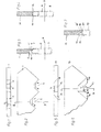
- FIG. 1 shows one Top view of the narrow side formed with notches a part of a flat key
- Fig. 2 is a side view
- FIG. 3 shows a section along the line III-III in Fig. 2, in addition a core pin, a housing pin as well as the division area are indicated.
- Fig. 4 one Section according to FIG. 3, but through a copied one Key.
- Fig. 5 a top view of that with another Execution of a notch formed narrow side a flat key
- Fig. 6 a side view of Fig. 5 and Fig. 7, a section along the line VII-VII in Fig. 6th with an indicated core pin.
- a flat key 1 for a cylinder lock or a locking system carries notches 2, 3 on his beard V-shaped running surfaces on which core pins a lock cylinder when inserting the Slide key 1 into a key channel until they reach the end position.
- a surface lying on the notch base the core pins their contact surfaces with spring-loaded housing pins in the division area between the cylinder core and Cylinder housing must be moved by one
- the notch 3 is one Support surface 5 or a web 5 'on the opposite Edge arranged.
- the core pin 6 executed separately, that is, it has a ring-shaped Heel area 7 with which he on the support surface 4th sits, the core pin 6 is positioned so that its interface with the associated sprung Housing pin 8 exactly in the division area 9, that is the circumferential surface in the cylinder housing rotatably Cylinder core lies. This can lock the cylinder become.
- the core pin 6 also carries the sales surface 7 towering extension 10, which in the notch 2 dips.
- the contour of the key bit as in Fig. 2 is shown by a sensor of a copy router the length as usual in the manufacture of duplicate keys scanned, then the feeler moves in the notches 2, 3 along the contact surfaces 4, 5. It results a copied duplicate key 11, as in the average III-III (Fig. 2) in Fig. 4 is shown.
- the controlling notch base 12 is in the position of the support surface 4 of the key 1. This is when inserting of the duplicate key 11 in the key channel of the Lock cylinder of the extension 10 of the core pin 6. As a result, the core pin 6 is over the dividing surface 9 postponed and blocked the saving process.
- FIG. 5 to 7 An alternative embodiment is shown in FIG. 5 to 7.
- a notch 14 is provided in a key 13, the one with a trapezoidal side milling cutter Contour oblique to the cross-sectional area of the key 13 was incised (Fig. 7). This results in V-shaped and additional against the longitudinal direction inclined inlet surfaces 15, 16 of the notch 14
- the notch base surface 17 also runs obliquely. She will 7 at its upper end in a second Machined horizontally, so that there is one results in a narrow contact surface 18 or a web (FIG. 5. 7).
- the Core pin 19 is executed again and carries an annular heel surface 20 with which he on the Bearing surface 18 abuts. Raises above the sales surface 20 an extension 21 in front, which is designed according to FIG. 7 as a cone is.
- the feeler of a copy router slides along the contour the key bit (Fig. 6), so that a duplicate fails again as shown in Fig. 4.
- the conical Extension 21 of the core pin 19 is in the Attempt to lock with the duplicate key on the notch base surface (12) and causes incorrect positioning the core pin 19 so that division is not reached. The locking process cannot be done with the duplicate key be carried out.
- the key 1 or 13 can in the longitudinal direction the flanks with profiling by grooves or ribs be designed as usual with flat keys is.
Landscapes
- Lock And Its Accessories (AREA)
Description
Claims (4)
- Schlüssel einer Schlüssel-Schloßkombination auf der Basis von Schließzylindern mit einem Zylinderkern mit Schlüsselkanal in dem mehrere Kernstifte radial in Bohrungen gegen gefederte Gehäusestifte aus einer Sperrstellung in eine Freigabestellung mittels eines die Verschiebelage der Stifte durch Kerben bestimmenden Flachschlüssel verschiebbar sind, wobei die Kerben im Schlüsselbart sägezahnartig aufeinander folgen, dadurch gekennzeichnet, daß in mindestens einer Kerbe (2, 3, 14) in Längsrichtung des Schlüssels (1, 13) etwa in Verlängerung einer Schlüsselseitenflache ein die Kerbe (2, 3, 14) überbrückender Steg (4', 5', 18') mit einer Auflagefläche (4, 5, 18) für den Kernstift (6, 19) vorgesehen ist, dass die Auflagefläche (4, 5, 18) des Steges (4', 5', 18') die Kerbe (2, 3, 14) in einer Tiefe überbrückt, die geringer als die Kerbentiefe ist, dass die Breite der Auflagefläche (4, 5, 18) geringer ist als die Schlüsselbreite und beispielsweise etwa ein Viertel der Schlüsselbreite beträgt.
- Schlüssel nach Anspruch 1, dadurch gekennzeichnet, daß als Kerbe (14) eine den Schlüsselquerschnitt schräg durchsetzende V-förmige Ausnehmung vorgesehen ist, deren im Schlüsselquerschnitt gesehen hochliegendes Ende zu der Auflagefläche (18) abgeflacht ist.
- Schlüssel nach den Ansprüchen 1 oder 2, dadurch gekennzeichnet, daß die im Schlüsselbart sägezahnartig aufeinanderfolgend vorgesehenen Kerben (2, 3, 14) die Auflageflächen (4, 5, 18) abwechselnd bzw. in unterschiedlicher Folge am linken bzw am rechten Querschnittsrand aufweisen.
- Schlüssel-Schloßkombination auf der Basis von Schließzylindern mit einem Zylinderkern mit Schlüsselkanal in dem mehrere Kernstifte radial in Bohrungen gegen gefederte Gehäusestifte aus einer Sperrstellung in eine Freigabestellung mittels eines die Verschiebelage der Stifte durch Kerben bestimmenden Flachschlüssels verschiebbar sind, wobei die Kerben im Schlüsselbart sägezahnartig aufeinander folgen, dadurch gekennzeichnet, daß in mindestens einer Kerbe (2, 3, 14) in Längsrichtung des Schlüssels (1, 13) etwa in Verlängerung einer Schlüsselseitenfläche ein die Kerbe (2, 3, 14) überbrückender Steg (4', 5', 18') mit einer Auflagefläche (4, 5, 18) für den Kernstift (6, 19) vorgesehen ist, dass die Auflagefläche (4, 5, 18) des Steges (4', 5', 18') die Kerbe (2, 3, 14) in einer Tiefe überbrückt, die geringer als die Kerbentiefe ist, daß die Breite der Auflagefläche (4, 5, 18) geringer ist als die Schlüsselbreite und beispielsweise etwa ein Viertel der Schlüsselbreite beträgt und daß der Kernstift (6, 19) kopfseitig im Querschnitt abgesetzt ist und die vorzugsweise als Kreisringfläche ausgebildete Absatzfläche (7, 20) einen diese überragenden Fortsatz (10, 21) umgibt.
Applications Claiming Priority (3)
| Application Number | Priority Date | Filing Date | Title |
|---|---|---|---|
| AT231392 | 1992-11-20 | ||
| AT231392A AT401546B (de) | 1992-11-20 | 1992-11-20 | Schlüssel und bzw. oder schloss |
| AT2313/92 | 1992-11-20 |
Publications (3)
| Publication Number | Publication Date |
|---|---|
| EP0599805A1 EP0599805A1 (de) | 1994-06-01 |
| EP0599805B1 EP0599805B1 (de) | 1996-03-06 |
| EP0599805B2 true EP0599805B2 (de) | 2001-06-06 |
Family
ID=3532047
Family Applications (1)
| Application Number | Title | Priority Date | Filing Date |
|---|---|---|---|
| EP93890230A Expired - Lifetime EP0599805B2 (de) | 1992-11-20 | 1993-11-19 | Schlüssel und bzw. oder Schloss |
Country Status (3)
| Country | Link |
|---|---|
| EP (1) | EP0599805B2 (de) |
| AT (1) | AT401546B (de) |
| DE (1) | DE59301792D1 (de) |
Families Citing this family (5)
| Publication number | Priority date | Publication date | Assignee | Title |
|---|---|---|---|---|
| US5943890A (en) * | 1996-10-31 | 1999-08-31 | Medeco Security Locks, Inc. | Cylinder lock and key assembly and hierarchical system therefor |
| DE29718647U1 (de) * | 1997-10-21 | 1997-12-11 | Schloßsicherungen Gera GmbH, 07548 Gera | Flachschlüssel für Zylinderschlösser |
| AT501473B8 (de) * | 2005-01-18 | 2007-02-15 | Evva Werke | Flachschlüssel |
| AT9157U1 (de) * | 2006-02-02 | 2007-05-15 | Evva Werke | Zylinderschloss sowie flachschlüssel |
| DE102006044106A1 (de) * | 2006-09-20 | 2008-04-03 | Dom Sicherheitstechnik Gmbh & Co Kg | Aus zwei parallel zueinander verlaufenden Steuerflanken aufweisenden Schlüssel und Zylinderschloss bestehendes Schließsystem |
Citations (1)
| Publication number | Priority date | Publication date | Assignee | Title |
|---|---|---|---|---|
| DE4036158A1 (de) † | 1989-12-15 | 1991-06-20 | Bauer Kaba Ag | Schliesszylinder und schluessel sowie schluesselrohling mit aufeinander abgestimmtem sicherheitselement |
Family Cites Families (9)
| Publication number | Priority date | Publication date | Assignee | Title |
|---|---|---|---|---|
| DE2344473B2 (de) * | 1973-09-04 | 1976-04-29 | Josef Voss KG, 5040 Brühl | Zylinderkern in einem zylinderschloss mit flachschluessel |
| DE2546551C3 (de) * | 1975-10-17 | 1978-09-07 | Fa. Wilhelm Karrenberg, 5620 Velbert | Zylinderschloß mit Flachschlüssel |
| CH606714A5 (de) * | 1976-05-20 | 1978-11-15 | Bauer Kaba Ag | |
| FR2413520A1 (fr) * | 1977-12-30 | 1979-07-27 | Fichet Bauche | Dispositif de serrure et cle |
| DE2924990B1 (de) * | 1979-06-21 | 1980-07-10 | Karrenberg Fa Wilhelm | Zylinderschloss mit Flachschluessel |
| FR2487414A1 (fr) * | 1980-07-23 | 1982-01-29 | Sodex Magister Expl Brevets Ne | Serrure a pistons a passe-partout |
| DE3119626C2 (de) * | 1981-05-16 | 1986-07-24 | Fa. Wilhelm Karrenberg, 5620 Velbert | Aus Flachzylinder und zugehörigen Flachschlüsseln bestehende Schließanlage |
| DE3326024A1 (de) * | 1983-07-20 | 1985-02-07 | Karrenberg, Wilhelm, 5620 Velbert | Flachschluessel fuer schliesszylinder von schliessanlagen |
| DE3935322A1 (de) * | 1989-08-01 | 1991-02-07 | Danijel Golub | Zylinderschloss |
-
1992
- 1992-11-20 AT AT231392A patent/AT401546B/de not_active IP Right Cessation
-
1993
- 1993-11-19 DE DE59301792T patent/DE59301792D1/de not_active Expired - Fee Related
- 1993-11-19 EP EP93890230A patent/EP0599805B2/de not_active Expired - Lifetime
Patent Citations (1)
| Publication number | Priority date | Publication date | Assignee | Title |
|---|---|---|---|---|
| DE4036158A1 (de) † | 1989-12-15 | 1991-06-20 | Bauer Kaba Ag | Schliesszylinder und schluessel sowie schluesselrohling mit aufeinander abgestimmtem sicherheitselement |
Also Published As
| Publication number | Publication date |
|---|---|
| DE59301792D1 (de) | 1996-04-11 |
| EP0599805B1 (de) | 1996-03-06 |
| AT401546B (de) | 1996-09-25 |
| EP0599805A1 (de) | 1994-06-01 |
| ATA231392A (de) | 1995-01-15 |
Similar Documents
| Publication | Publication Date | Title |
|---|---|---|
| DE8017685U1 (de) | Schliesszylinder mit passendem schluessel | |
| AT403606B (de) | Sicherheitsschloss und flachschlüssel für ein solches | |
| EP1055788B1 (de) | Flachschlüssel und Zylinderschloss | |
| EP0621384B1 (de) | Schlüssel und Drehschliesszylinder für ein Sicherheitsschloss | |
| DE2810756A1 (de) | Vorhaengeschloss | |
| DE2717799A1 (de) | Zylinderschloss | |
| DE8017686U1 (de) | Zylinderschloss | |
| DE3101418C2 (de) | Riegel-Abschließvorrichtung | |
| DE2917034A1 (de) | Einbau-doppelzylinder fuer ein sicherheitsschloss | |
| DE3128320C2 (de) | Schließzylinder | |
| EP0599805B2 (de) | Schlüssel und bzw. oder Schloss | |
| DE2546551C3 (de) | Zylinderschloß mit Flachschlüssel | |
| EP0712980B1 (de) | Zylinderschloss mit Zylinderkern und Zylindergehäuse | |
| EP0248787A2 (de) | Drehzylinderschlossschlüssel | |
| EP3872282B1 (de) | Schloss-schlüssel-system | |
| AT396706B (de) | Schliesszylinder | |
| EP0255986B1 (de) | Schloss-Schlüsselkombination | |
| CH651350A5 (en) | Cylinder lock with a reversible key | |
| DE29718647U1 (de) | Flachschlüssel für Zylinderschlösser | |
| EP0305336B1 (de) | Rotorhülse | |
| DE9218855U1 (de) | Codierbares Zylinderschloß | |
| DE3904333A1 (de) | Aus doppelschliesszylinder und schluesseln bestehende schliessvorrichtung | |
| DE8915331U1 (de) | Zylinderschloß mit einem auswechselbaren Schließzylinder | |
| EP1156179A2 (de) | Schliesszylinder | |
| EP3971371B1 (de) | Schloss-schlüssel-system |
Legal Events
| Date | Code | Title | Description |
|---|---|---|---|
| PUAI | Public reference made under article 153(3) epc to a published international application that has entered the european phase |
Free format text: ORIGINAL CODE: 0009012 |
|
| AK | Designated contracting states |
Kind code of ref document: A1 Designated state(s): BE CH DE FR GB LI NL SE |
|
| 17P | Request for examination filed |
Effective date: 19940518 |
|
| 17Q | First examination report despatched |
Effective date: 19950721 |
|
| GRAA | (expected) grant |
Free format text: ORIGINAL CODE: 0009210 |
|
| AK | Designated contracting states |
Kind code of ref document: B1 Designated state(s): BE CH DE FR GB LI NL SE |
|
| REG | Reference to a national code |
Ref country code: CH Ref legal event code: NV Representative=s name: PATENTANWALTSBUERO FELDMANN AG |
|
| GBT | Gb: translation of ep patent filed (gb section 77(6)(a)/1977) |
Effective date: 19960308 |
|
| REF | Corresponds to: |
Ref document number: 59301792 Country of ref document: DE Date of ref document: 19960411 |
|
| ET | Fr: translation filed | ||
| PLBQ | Unpublished change to opponent data |
Free format text: ORIGINAL CODE: EPIDOS OPPO |
|
| PLBI | Opposition filed |
Free format text: ORIGINAL CODE: 0009260 |
|
| PLBF | Reply of patent proprietor to notice(s) of opposition |
Free format text: ORIGINAL CODE: EPIDOS OBSO |
|
| 26 | Opposition filed |
Opponent name: AUGUST BOERKEY NACHF. GMBH Effective date: 19961203 |
|
| NLR1 | Nl: opposition has been filed with the epo |
Opponent name: AUGUST BOERKEY NACHF. GMBH |
|
| PLBF | Reply of patent proprietor to notice(s) of opposition |
Free format text: ORIGINAL CODE: EPIDOS OBSO |
|
| RAP2 | Party data changed (patent owner data changed or rights of a patent transferred) |
Owner name: KABA GEGE GMBH |
|
| NLT2 | Nl: modifications (of names), taken from the european patent patent bulletin |
Owner name: KABA GEGE GMBH |
|
| PLAW | Interlocutory decision in opposition |
Free format text: ORIGINAL CODE: EPIDOS IDOP |
|
| PLAW | Interlocutory decision in opposition |
Free format text: ORIGINAL CODE: EPIDOS IDOP |
|
| PUAH | Patent maintained in amended form |
Free format text: ORIGINAL CODE: 0009272 |
|
| STAA | Information on the status of an ep patent application or granted ep patent |
Free format text: STATUS: PATENT MAINTAINED AS AMENDED |
|
| 27A | Patent maintained in amended form |
Effective date: 20010606 |
|
| AK | Designated contracting states |
Kind code of ref document: B2 Designated state(s): BE CH DE FR GB LI NL SE |
|
| REG | Reference to a national code |
Ref country code: CH Ref legal event code: AEN Free format text: AUFRECHTERHALTUNG DES PATENTES IN GEAENDERTER FORM |
|
| NLR2 | Nl: decision of opposition | ||
| REG | Reference to a national code |
Ref country code: CH Ref legal event code: PFA Free format text: GRUNDMANN SCHLIESSTECHNIK GESELLSCHAFT M.B.H. TRANSFER- KABA GEGE GMBH |
|
| GBTA | Gb: translation of amended ep patent filed (gb section 77(6)(b)/1977) | ||
| NLR3 | Nl: receipt of modified translations in the netherlands language after an opposition procedure | ||
| ET3 | Fr: translation filed ** decision concerning opposition | ||
| NLS | Nl: assignments of ep-patents |
Owner name: KABA GEGE SCHLIESSTECHNIK GMBH |
|
| NLT1 | Nl: modifications of names registered in virtue of documents presented to the patent office pursuant to art. 16 a, paragraph 1 |
Owner name: KABA GEGE GMBH |
|
| REG | Reference to a national code |
Ref country code: GB Ref legal event code: IF02 |
|
| REG | Reference to a national code |
Ref country code: GB Ref legal event code: 732E |
|
| REG | Reference to a national code |
Ref country code: FR Ref legal event code: TP Ref country code: FR Ref legal event code: CD |
|
| PGFP | Annual fee paid to national office [announced via postgrant information from national office to epo] |
Ref country code: CH Payment date: 20030227 Year of fee payment: 10 |
|
| PGFP | Annual fee paid to national office [announced via postgrant information from national office to epo] |
Ref country code: DE Payment date: 20031021 Year of fee payment: 11 Ref country code: FR Payment date: 20031021 Year of fee payment: 11 |
|
| PGFP | Annual fee paid to national office [announced via postgrant information from national office to epo] |
Ref country code: SE Payment date: 20031031 Year of fee payment: 11 |
|
| PGFP | Annual fee paid to national office [announced via postgrant information from national office to epo] |
Ref country code: BE Payment date: 20031103 Year of fee payment: 11 |
|
| PGFP | Annual fee paid to national office [announced via postgrant information from national office to epo] |
Ref country code: NL Payment date: 20031128 Year of fee payment: 11 |
|
| PG25 | Lapsed in a contracting state [announced via postgrant information from national office to epo] |
Ref country code: LI Free format text: LAPSE BECAUSE OF NON-PAYMENT OF DUE FEES Effective date: 20031130 Ref country code: CH Free format text: LAPSE BECAUSE OF NON-PAYMENT OF DUE FEES Effective date: 20031130 |
|
| REG | Reference to a national code |
Ref country code: CH Ref legal event code: PL |
|
| PG25 | Lapsed in a contracting state [announced via postgrant information from national office to epo] |
Ref country code: SE Free format text: LAPSE BECAUSE OF NON-PAYMENT OF DUE FEES Effective date: 20041120 |
|
| PG25 | Lapsed in a contracting state [announced via postgrant information from national office to epo] |
Ref country code: BE Free format text: LAPSE BECAUSE OF NON-PAYMENT OF DUE FEES Effective date: 20041130 |
|
| BERE | Be: lapsed |
Owner name: *KABA GEGE G.M.B.H. Effective date: 20041130 |
|
| PG25 | Lapsed in a contracting state [announced via postgrant information from national office to epo] |
Ref country code: NL Free format text: LAPSE BECAUSE OF NON-PAYMENT OF DUE FEES Effective date: 20050601 Ref country code: DE Free format text: LAPSE BECAUSE OF NON-PAYMENT OF DUE FEES Effective date: 20050601 |
|
| EUG | Se: european patent has lapsed | ||
| PG25 | Lapsed in a contracting state [announced via postgrant information from national office to epo] |
Ref country code: FR Free format text: LAPSE BECAUSE OF NON-PAYMENT OF DUE FEES Effective date: 20050729 |
|
| NLV4 | Nl: lapsed or anulled due to non-payment of the annual fee |
Effective date: 20050601 |
|
| REG | Reference to a national code |
Ref country code: FR Ref legal event code: ST |
|
| BERE | Be: lapsed |
Owner name: *KABA GEGE G.M.B.H. Effective date: 20041130 |
|
| PGFP | Annual fee paid to national office [announced via postgrant information from national office to epo] |
Ref country code: GB Payment date: 20121122 Year of fee payment: 20 |
|
| REG | Reference to a national code |
Ref country code: GB Ref legal event code: PE20 Expiry date: 20131118 |
|
| PG25 | Lapsed in a contracting state [announced via postgrant information from national office to epo] |
Ref country code: GB Free format text: LAPSE BECAUSE OF EXPIRATION OF PROTECTION Effective date: 20131118 |