EP0595239B1 - Beschickbehälter für die Aufnahme von feinteiligem oder körnigem Beschickgut - Google Patents
Beschickbehälter für die Aufnahme von feinteiligem oder körnigem Beschickgut Download PDFInfo
- Publication number
- EP0595239B1 EP0595239B1 EP93117276A EP93117276A EP0595239B1 EP 0595239 B1 EP0595239 B1 EP 0595239B1 EP 93117276 A EP93117276 A EP 93117276A EP 93117276 A EP93117276 A EP 93117276A EP 0595239 B1 EP0595239 B1 EP 0595239B1
- Authority
- EP
- European Patent Office
- Prior art keywords
- suction
- port
- connection piece
- cylinder chamber
- control valve
- Prior art date
- Legal status (The legal status is an assumption and is not a legal conclusion. Google has not performed a legal analysis and makes no representation as to the accuracy of the status listed.)
- Expired - Lifetime
Links
- 239000000463 material Substances 0.000 title claims description 6
- 229920003023 plastic Polymers 0.000 claims description 3
- 239000004033 plastic Substances 0.000 claims description 3
- 238000005273 aeration Methods 0.000 claims 4
- 238000009423 ventilation Methods 0.000 description 8
- 238000010276 construction Methods 0.000 description 3
- 239000003546 flue gas Substances 0.000 description 1
- 239000008187 granular material Substances 0.000 description 1
Images
Classifications
-
- B—PERFORMING OPERATIONS; TRANSPORTING
- B65—CONVEYING; PACKING; STORING; HANDLING THIN OR FILAMENTARY MATERIAL
- B65G—TRANSPORT OR STORAGE DEVICES, e.g. CONVEYORS FOR LOADING OR TIPPING, SHOP CONVEYOR SYSTEMS OR PNEUMATIC TUBE CONVEYORS
- B65G53/00—Conveying materials in bulk through troughs, pipes or tubes by floating the materials or by flow of gas, liquid or foam
- B65G53/34—Details
- B65G53/60—Devices for separating the materials from propellant gas
Definitions
- the invention relates to a loading container for receiving finely divided or granular material to be loaded, with a filling device, funnel-shaped container bottom and outlet nozzle on the container bottom, the filling device having on the one hand a filling nozzle opening into the inside of the loading container and on the other hand a suction fan connected via a suction nozzle.
- the filling of the interior of the loading container takes place via the suction fan, i.e. by sucking in the load.
- valves are arranged in the filling nozzle, in the suction nozzle and in front of the suction fan, which are controlled by a special control device so that the filling material is filled in via the filling nozzle, but ventilation of the interior of the loading container can also be carried out.
- the known measures are complex because they require a plurality of valves and actuators for the control movement of the valves.
- a known filter system (DE-A-2 748 735) two mutually independent filter devices are provided in the upper part of a loading container, the clean air sides of which can be connected either to a suction fan or to the atmosphere via respectively associated valves.
- the clean air side of the other Filters uncoupled from the suction fan and connected to the atmosphere so that atmospheric air can enter the container via the clean air side of the filter, from which it is sucked off again by the suction fan via the other filter.
- Another known filter system for flue gases (US-A-2 276 805) has a controllable valve between two containers and a further controllable valve between a container and a suction fan.
- the two valves are driven in opposite directions, so that the vacuum which is established in the one container under the action of the suction fan is abruptly released and air can flow through an opening which is connected to the atmosphere to the clean side of the filter.
- the invention is based on the object of further developing a loading container of the construction described at the outset in such a way that filling but also ventilation are possible in a very simple manner and in addition special functional advantages are achieved.
- the invention is based on the knowledge that in a loading container of the construction described at the outset, the filling and the ventilation can be effected with a single valve. If you work according to the teaching of the invention, it is achieved at the same time that the suction fan continues to work in the ventilation, which is advantageous because the start-up and drainage, especially of large fans, is very complex and is no longer necessary according to the invention. Another advantage is that the ventilation takes place very suddenly. This causes the flexible filter walls to inflate outward as it were and to release deposited loading material which falls down into the loading container. It goes without saying that when loading plastic screw presses, several loading containers according to the invention can be combined to form an aggregate, with all loading containers of the aggregate being connected to a single suction fan.
- the filling device 2 has, on the one hand, a filling nozzle 4 opening into the interior of the charging container and, on the other hand, a suction fan 7 connected via a suction nozzle 5 and a suction line 6.
- the arrangement is such that a filter 9 with flexible filter walls 8 is arranged in front of the suction nozzle 5 and that a control valve 10 is arranged in the suction direction behind the suction nozzle 5, with which the loading container interior via the suction line 6 to the suction fan 7 or at 11 the atmosphere is connectable.
- the suction line 6 can be closed while the suction blower 7 is working.
- FIGS. 2 and 3 How the control valve 10 is designed in detail in the exemplary embodiment is shown in FIGS. 2 and 3.
- FIG. 2 the position of the control valve 10 is drawn, in which the piston valve 12 has the bore 13 for the suction line 6 and the bore 14 releases for the suction nozzle 5, but closes the atmosphere bores 15.
- FIG. 3 conversely, the bore 13 for the suction line 6 is closed, while the atmosphere bores 15 and the bore 14 for the suction nozzle 5 are free.
- the control valve 10 has a control valve cylinder chamber 16 which has a cylinder chamber cover 17 on the suction blower chamber side with at least one bore 13 for the connection of the suction line 6 and an opposite cylinder chamber cover 18 on the atmosphere side with at least one atmospheric bore 15.
- the cylinder chamber 16 has the bore 14 for the suction nozzle 5 in the region of its center.
- the piston slide 12 In the control valve cylinder chamber 16 there is the piston slide 12 with the control rod 19 guided outwards, which in the suction position releases the bore 13 for the suction line 6 and the bore 14 for the suction nozzle 5 , but the ventilation holes 15 closes.
- the ventilation bores 15 and the bore 14 for the suction nozzle 5 are free, while the bore 13 is closed for the connection of the suction line 6.
Landscapes
- Engineering & Computer Science (AREA)
- Mechanical Engineering (AREA)
- Basic Packing Technique (AREA)
- Supply Of Fluid Materials To The Packaging Location (AREA)
Description
- Die Erfindung betrifft einen Beschickbehälter für die Aufnahme von feinteiligem oder körnigem Beschickgut, - mit Befülleinrichtung, trichterförmigem Behälterboden und Auslaufstutzen am Behälterboden, wobei die Befülleinrichtung einerseits einen in den Beschickbehälterinnenraum einmündenden Befüllstutzen und andererseits ein über einen Absaugstutzen angeschlossenes Sauggebläse aufweist.
- Bei dem aus der Praxis bekannten Beschickbehälter des vorstehend beschriebenen Aufbaus erfolgt die Befüllung des Beschickbehälterinnenraumes über das Sauggeblässe, d.h. durch Einsaugen des Beschickgutes. Dazu sind im Befüllstutzen, im Absaugstutzen sowie vor dem Sauggebläse Ventile angeordnet, die über eine besondere Steuereinrichtung so gesteuert werden, daß über den Befüllstutzen ein Einfüllen des Beschickgutes erfolgt, aber auch eine Belüftung des Beschickbehälterinnenraumes durchgeführt werden kann. Die bekannten Maßnahmen sind aufwendig, weil sie eine Mehrzahl von Ventilen und Stelltriebe für die Steuerbewegung der Ventile erforderlich machen.
- Bei einer bekannten Filteranlage (DE-A-2 748 735) sind im oberen Teil eines Beschickbehälters zwei voneinander unabhängige Filtereinrichtungen vorgesehen, deren Reinluftseiten über jeweils zugeordnete Ventile entweder mit einem Sauggebläse oder mit der Atmosphäre verbindbar sind. Zum Reinigen jeweils eines der Filter wird die Reinluftseite des anderen Filters vom Sauggebläse abgekoppelt und an die Atmosphäre angeschlossen, so daß atmosphärische Luft über die Reinluftseite des Filters in den Behälter eintreten kann, aus dem sie vom Sauggebläse über das andere Filter wieder abgesaugt wird.
- Eine andere bekannte Filteranlage für Rauchgase (US-A-2 276 805) weist zwischen zwei Behältern ein steuerbares Ventil auf und zwischen einem Behälter und einem Sauggebläse ein weiteres steuerbares Ventil. Die beiden Ventile werden gegenläufig angesteuert, so daß das sich in dem einen Behälter unter der Wirkung des Sauggebläses einstellende Vakuum schlagartig aufgehoben wird und Luft durch eine mit der Atmosphäre in Verbindung stehende Öffnung auf die Reinseite des Filters strömen kann.
- Der Erfindung liegt die Aufgabe zugrunde, einen Beschickbehälter des eingangs beschriebenen Aufbaus so weiter auszubilden, daß auf sehr einfache Weise das Befüllen, aber auch die Belüftung möglich sind und darüber hinaus besondere funktionelle Vorteile erreicht werden.
- Diese Aufgabe wird mit einem Beschickbehälter gemäß dem einzigen Patentanspruch gelöst.
- Die Erfindung geht von der Erkenntnis aus, daß bei einem Beschickbehälter des eingangs beschriebenen Aufbaus das Befüllen und die Belüftung mit einem einzigen Ventil bewirkt werden können. Arbeitet man nach der Lehre der Erfindung, so wird gleichzeitig erreicht, daß das Sauggebläse bei der Belüftung weiterarbeitet, was von Vorteil ist, weil das Anlaufen und Ablaufen insbesondere von großen Gebläsen sehr aufwendig ist und erfindungsgemäß nicht mehr erforderlich ist. Von Vorteil ist aber auch, daß die Belüftung sehr plötzlich erfolgt. Das bewirkt, daß die flexiblen Filterwände sich gleichsam nach außen aufblähen und abgesetzes Beschickgut freigeben, welches in den Beschickbehälter nach unten fällt. Es versteht sich, daß beim Beschicken von Kunststoff-Schneckenpressen, mehrere erfindungsgemäße Beschickbehälter zu einem Aggregat zusammengefaßt werden können, wobei alle Beschickbehälter des Aggregates an ein einziges Sauggebläse angeschlossen werden.
- Im folgenden wird die Erfindung anhand einer lediglich ein Ausführungsbeispiel darstellenden Zeichnung ausführlicher erläutert. Es zeigen in schematischer Darstellung
- Fig. 1
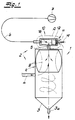
- einen Vertikalschnitt durch einen erfindungsgemäßen Beschickbehälter,
- Fig. 2
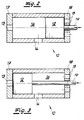
- in gegenüber der Fig. 1 wesentlich vergrößertem Maßstab den Ausschnitt A aus dem Gegenstand nach Fig. 1, nämlich das Steuerventil,
- Fig. 3
- den Gegenstand nach Fig. 2 in anderer Funktionsstellung.
- Der in den Figuren dargestellte Beschickbehälter 1 ist für die Aufnahme von feinteiligem oder körnigem Beschickgut bestimmt. Das Beschickgut wird aus dem Beschickbehälter 1 einer nachgeordneten Kunststoff-Schneckenpresse zugeführt. Sie wird unten an den Auslauf des Beschickbehälters 1 angeschlossen. Zum grundsätzlichen Aufbau gehören
- eine Befülleinrichtung 2,
- ein trichterförmiger Behälterboden 3 und
- Auslaufstutzen 3a am Behälterboden 3.
- Die Befülleinrichtung 2 weist einerseits einen in den Beschickbehälterinnenraum einmündenden Befüllstutzen 4 und andererseits ein über einen Absaugstutzen 5 und eine Saugleitung 6 angeschlossenes Sauggebläse 7 auf. Die Anordnung ist so getroffen, daß vor dem Absaugstutzen 5 ein Filter 9 mit flexiblen Filterwänden 8 angeordnet ist und daß in Absaugrichtung hinter dem Absaugstutzen 5 ein Steuerventil 10 angeordnet ist, mit dem der Beschickbehälterinnenraum über die Saugleitung 6 an das Sauggebläse 7 oder bei 11 an die Atmosphäre anschließbar ist. Dabei ist bei Anschluß des Beschickbehälterinnenraumes an die Atmosphäre die Saugleitung 6 bei arbeitendem Sauggebläse 7 verschließbar.
- Wie im Ausführungsbeispiel das Steuerventil 10 im einzelnen gestaltet ist, ergibt sich aus den Fig. 2 und 3. In der Fig. 2 ist die Stellung des Steuerventils 10 gezeichnet, bei der der Kolbenschieber 12 die Bohrung 13 für die Saugleitung 6 sowie die Bohrung 14 für den Absaugstutzen 5 freigibt, die Atmosphärenbohrungen 15 aber verschließt. In der Fig. 3 ist umgekehrt die Bohrung 13 für die Saugleitung 6 verschlossen, während die Atmosphärenbohrungen 15 und die Bohrung 14 für den Absaugstutzen 5 frei sind. Das Steuerventil 10 besitzt einen Steuerventilzylinderraum 16, der einen sauggebläseraumseitigen Zylinderraumdeckel 17 mit zumindest einer Bohrung 13 für den Anschluß der Saugleitung 6 und einen gegenüberliegenden atmosphärenseitigen Zylinderraumdeckel 18 mit zumindest einer Atmospährenbohrung 15 aufweist. Der Zylinderraum 16 besitzt im Bereich seiner Mitte die Bohrung 14 für den Absaugstutzen 5. Im Steuerventilzylinderraum 16 befindet sich der Kolbenschieber 12 mit nach außen geführter Steuerstange 19, der in Absaugstellung die Bohrung 13 für die Saugleitung 6 sowie die Bohrung 14 für den Absaugstutzen 5 freigibt, die Belüftungsbohrungen 15 aber verschließt. Umgekehrt gibt in der Belüftungsstellung der Kolbenschieber 12 die Belüftungsbohrungen 15 und die Bohrung 14 für den Absaugstutzen 5 frei, während die Bohrung 13 für den Anschluß der Saugleitung 6 verschlossen ist.
Claims (1)
- Beschickbehälter (1) für die Aufnahme von feinteiligem oder körnigem Beschickgut, das einer nachgeordneten Kunststoff-Schneckenpresse zugeführt wird, - mitBefülleinrichtung (2),trichterförmigem Behälterboden (3) undAuslaufstutzen (3a) am Behälterboden (3),wobei die Befülleinrichtung (2) einerseits einen in den Beschickbehälterinnenraum einmündenden Befüllstutzen (4) und andererseits ein über einen Absaugstutzen (5) und eine Saugleitung (6) angeschlossenes Sauggebläse (7) aufweist, dadurch gekennzeichnet, daß vor dem Absaugstutzen (5) ein Filter (9) mit flexiblen Filterwänden (8) angeordnet ist, wobei in Absaugrichtung hinter dem Absaugstutzen (5) ein Steuerventil (10) angeordnet ist, mit dem der Behälterinnenraum über die Saugleitung (6) entweder an das Sauggebläse (7) oder an die Atmosphäre anschließbar ist sowie bei Anschluß des Beschickbehälterinnenraumes an die Atmosphäre die Saugleitung (6) bei arbeitendem Sauggebläse (7) verschließbar ist, daß das Steuerventil (10) einen Steuerventilzylinderraum (16) und einen sauggebläseraumseitigen Zylinderraumdeckel (17) mit zumindest einer Bohrung (13) für den Anschluß der Saugleitung (6) und einen gegenüberliegenden atmosphärenseitigen Zylinderraumdeckel (18) mit zumindest einer Belüftungsbohrung (15) aufweist, daß fernerhin der Steuerzylinderraum (16) im Bereich seiner Mitte eine Bohrung (14) für den Absaugstutzen(5) aufweist und daß im Steuerventilzylinderraum (10) ein Kolbenschieber (12) mit nach außen geführter Steuerstange (19) geführt ist, der in Absaugstellung die Bohrung (13) für den Anschluß der Saugleitung (6) sowie die Bohrung (14) für den Absaugstutzen (5) freigibt und die Belüftungsbohrung (15) verschließt und der in Belüftungsstellung die Belüftungsbohrung (15) sowie die Bohrung (14) für den Absaugstutzen (5) freigibt und die Bohrung (13) für den Anschluß der Saugleitung (6) verschließt.
Applications Claiming Priority (2)
| Application Number | Priority Date | Filing Date | Title |
|---|---|---|---|
| DE9214620U | 1992-10-28 | ||
| DE9214620U DE9214620U1 (de) | 1992-10-28 | 1992-10-28 | Beschickbehälter für die Aufnahme von feinteiligem oder körnigem Beschickgut |
Publications (2)
| Publication Number | Publication Date |
|---|---|
| EP0595239A1 EP0595239A1 (de) | 1994-05-04 |
| EP0595239B1 true EP0595239B1 (de) | 1997-12-29 |
Family
ID=6885368
Family Applications (1)
| Application Number | Title | Priority Date | Filing Date |
|---|---|---|---|
| EP93117276A Expired - Lifetime EP0595239B1 (de) | 1992-10-28 | 1993-10-25 | Beschickbehälter für die Aufnahme von feinteiligem oder körnigem Beschickgut |
Country Status (2)
| Country | Link |
|---|---|
| EP (1) | EP0595239B1 (de) |
| DE (2) | DE9214620U1 (de) |
Citations (1)
| Publication number | Priority date | Publication date | Assignee | Title |
|---|---|---|---|---|
| DE2748735A1 (de) * | 1977-10-29 | 1979-05-03 | Motan Gmbh | Saugfoerdergeraet fuer koerniges oder pulverfoermiges transportgut, insbesondere kunststoff |
Family Cites Families (3)
| Publication number | Priority date | Publication date | Assignee | Title |
|---|---|---|---|---|
| US2276805A (en) * | 1940-06-22 | 1942-03-17 | Jr Edgar B Tolman | Apparatus for cleaning filter surfaces of pneumatic conveyer apparatus |
| NL7203924A (de) * | 1971-04-24 | 1972-10-26 | ||
| CH544023A (de) * | 1972-07-05 | 1973-11-15 | Eastern Cyclone Ind Inc | Vorrichtung zum Ausscheiden von festem Material aus einem Förderluftstrom |
-
1992
- 1992-10-28 DE DE9214620U patent/DE9214620U1/de not_active Expired - Lifetime
-
1993
- 1993-10-25 DE DE59307888T patent/DE59307888D1/de not_active Expired - Fee Related
- 1993-10-25 EP EP93117276A patent/EP0595239B1/de not_active Expired - Lifetime
Patent Citations (1)
| Publication number | Priority date | Publication date | Assignee | Title |
|---|---|---|---|---|
| DE2748735A1 (de) * | 1977-10-29 | 1979-05-03 | Motan Gmbh | Saugfoerdergeraet fuer koerniges oder pulverfoermiges transportgut, insbesondere kunststoff |
Also Published As
| Publication number | Publication date |
|---|---|
| DE9214620U1 (de) | 1993-04-15 |
| DE59307888D1 (de) | 1998-02-05 |
| EP0595239A1 (de) | 1994-05-04 |
Similar Documents
| Publication | Publication Date | Title |
|---|---|---|
| DE2501803C2 (de) | Anlage zum Sammeln und Fördern von vorsortierten Gütern verschiedener Gutklassen | |
| EP0423559B1 (de) | Pneumatische Saugförderanlage zum gravimetrischen Zuteilen von Schüttgutkomponenten | |
| EP0005542A1 (de) | Vorrichtung zur Abgabe abgemessener Mengen feinkörnigen Schüttgutes | |
| DE3716047C2 (de) | ||
| DE2205203C3 (de) | Fahrbare Verladevorrichtung für feinkörniges und staubförmiges Schüttgut | |
| DE3001652C2 (de) | Saugkanal einer Fördereinrichtung | |
| EP0595239B1 (de) | Beschickbehälter für die Aufnahme von feinteiligem oder körnigem Beschickgut | |
| DE3930954C2 (de) | Mischvorrichtung | |
| DE3319908C2 (de) | ||
| WO2005012147A2 (de) | Verfahren und vorrichtung zum transport von bauteilen in einer rohrartigen förderstrecke | |
| DE3022346A1 (de) | Mischsilo fuer schuettgut | |
| DE1152058B (de) | Silo fuer pulverfoermige und fluessige Gueter, insbesondere Zement | |
| EP0714016A2 (de) | Behälter, insbesondere mit flexiblem Innenteil | |
| DE19711889A1 (de) | Verfahren zur Handhabung von Schüttgütern und Schüttgutbehälter zur Durchführung des Verfahrens | |
| DE4210472C2 (de) | Wiege- und Abfüllvorrichtung für durch Luft transportierbares flockiges Material | |
| DE3613464C2 (de) | Vorrichtung zum Transportieren von staubförmigem oder körnigem Gut - Baustoffmischungen - (Fördergut) zur Verwendung im Untertagebergbau | |
| DE3021869A1 (de) | Silofahrzeug | |
| DE20203463U1 (de) | Speicheranordnung zur vorübergehenden Aufnahme von zur Betonfertigung einsetzbarem pulverartigem Material, insbesondere Bindemittel | |
| DE29913368U1 (de) | Vorrichtung zum Dosieren von mehligen bis körnigen Schüttgütern | |
| DE2938626C2 (de) | Schüttgutaufnahmevorrichtung für einen pneumatischen Druckförderer | |
| EP0073833A1 (de) | Pneumatiksystem zur sicherung der luftabsaugung aus silozellen | |
| DE1865881U (de) | Fahrbarer kipptank fuer staubfoermiges bzw. mehliges gut, insbesondere backmehl. | |
| EP4321780A1 (de) | Schieberventil, modul mit einem ventil und anlage zum fördern von schüttgut mit ventilen | |
| DE9418825U1 (de) | Zuteilungs- und Fördervorrichtung für Schüttgut | |
| CH471027A (de) | Transportbehälter für Schüttgut, auf Lastkraftwagen oder -anhänger |
Legal Events
| Date | Code | Title | Description |
|---|---|---|---|
| PUAI | Public reference made under article 153(3) epc to a published international application that has entered the european phase |
Free format text: ORIGINAL CODE: 0009012 |
|
| AK | Designated contracting states |
Kind code of ref document: A1 Designated state(s): AT BE CH DE DK ES FR GB GR IE IT LI LU MC NL PT SE |
|
| 17P | Request for examination filed |
Effective date: 19940712 |
|
| RBV | Designated contracting states (corrected) |
Designated state(s): CH DE DK FR GB IT LI NL |
|
| 17Q | First examination report despatched |
Effective date: 19960813 |
|
| GRAG | Despatch of communication of intention to grant |
Free format text: ORIGINAL CODE: EPIDOS AGRA |
|
| GRAG | Despatch of communication of intention to grant |
Free format text: ORIGINAL CODE: EPIDOS AGRA |
|
| GRAH | Despatch of communication of intention to grant a patent |
Free format text: ORIGINAL CODE: EPIDOS IGRA |
|
| GRAH | Despatch of communication of intention to grant a patent |
Free format text: ORIGINAL CODE: EPIDOS IGRA |
|
| GRAA | (expected) grant |
Free format text: ORIGINAL CODE: 0009210 |
|
| AK | Designated contracting states |
Kind code of ref document: B1 Designated state(s): CH DE DK FR GB IT LI NL |
|
| PG25 | Lapsed in a contracting state [announced via postgrant information from national office to epo] |
Ref country code: NL Free format text: LAPSE BECAUSE OF FAILURE TO SUBMIT A TRANSLATION OF THE DESCRIPTION OR TO PAY THE FEE WITHIN THE PRESCRIBED TIME-LIMIT Effective date: 19971229 Ref country code: DK Free format text: LAPSE BECAUSE OF NON-PAYMENT OF DUE FEES Effective date: 19971229 |
|
| REG | Reference to a national code |
Ref country code: CH Ref legal event code: EP |
|
| REF | Corresponds to: |
Ref document number: 59307888 Country of ref document: DE Date of ref document: 19980205 |
|
| ITF | It: translation for a ep patent filed | ||
| GBT | Gb: translation of ep patent filed (gb section 77(6)(a)/1977) |
Effective date: 19980407 |
|
| ET | Fr: translation filed | ||
| NLV1 | Nl: lapsed or annulled due to failure to fulfill the requirements of art. 29p and 29m of the patents act | ||
| PG25 | Lapsed in a contracting state [announced via postgrant information from national office to epo] |
Ref country code: LI Free format text: LAPSE BECAUSE OF NON-PAYMENT OF DUE FEES Effective date: 19981031 Ref country code: CH Free format text: LAPSE BECAUSE OF NON-PAYMENT OF DUE FEES Effective date: 19981031 |
|
| PLBE | No opposition filed within time limit |
Free format text: ORIGINAL CODE: 0009261 |
|
| STAA | Information on the status of an ep patent application or granted ep patent |
Free format text: STATUS: NO OPPOSITION FILED WITHIN TIME LIMIT |
|
| 26N | No opposition filed | ||
| REG | Reference to a national code |
Ref country code: CH Ref legal event code: PL |
|
| REG | Reference to a national code |
Ref country code: GB Ref legal event code: IF02 |
|
| PGFP | Annual fee paid to national office [announced via postgrant information from national office to epo] |
Ref country code: FR Payment date: 20051014 Year of fee payment: 13 |
|
| PGFP | Annual fee paid to national office [announced via postgrant information from national office to epo] |
Ref country code: GB Payment date: 20051017 Year of fee payment: 13 |
|
| PGFP | Annual fee paid to national office [announced via postgrant information from national office to epo] |
Ref country code: IT Payment date: 20061031 Year of fee payment: 14 |
|
| GBPC | Gb: european patent ceased through non-payment of renewal fee |
Effective date: 20061025 |
|
| REG | Reference to a national code |
Ref country code: FR Ref legal event code: ST Effective date: 20070629 |
|
| PG25 | Lapsed in a contracting state [announced via postgrant information from national office to epo] |
Ref country code: GB Free format text: LAPSE BECAUSE OF NON-PAYMENT OF DUE FEES Effective date: 20061025 |
|
| PG25 | Lapsed in a contracting state [announced via postgrant information from national office to epo] |
Ref country code: FR Free format text: LAPSE BECAUSE OF NON-PAYMENT OF DUE FEES Effective date: 20061031 |
|
| PGFP | Annual fee paid to national office [announced via postgrant information from national office to epo] |
Ref country code: DE Payment date: 20081022 Year of fee payment: 16 |
|
| PG25 | Lapsed in a contracting state [announced via postgrant information from national office to epo] |
Ref country code: IT Free format text: LAPSE BECAUSE OF NON-PAYMENT OF DUE FEES Effective date: 20071025 |
|
| PG25 | Lapsed in a contracting state [announced via postgrant information from national office to epo] |
Ref country code: DE Free format text: LAPSE BECAUSE OF NON-PAYMENT OF DUE FEES Effective date: 20100501 |