EP0583218A1 - Procédé et dispositif pour transporter des paquets tubulaires de produits imprimés et leur assemblage comme unités d'expédition - Google Patents
Procédé et dispositif pour transporter des paquets tubulaires de produits imprimés et leur assemblage comme unités d'expédition Download PDFInfo
- Publication number
- EP0583218A1 EP0583218A1 EP93810359A EP93810359A EP0583218A1 EP 0583218 A1 EP0583218 A1 EP 0583218A1 EP 93810359 A EP93810359 A EP 93810359A EP 93810359 A EP93810359 A EP 93810359A EP 0583218 A1 EP0583218 A1 EP 0583218A1
- Authority
- EP
- European Patent Office
- Prior art keywords
- packages
- point
- conveying direction
- loading
- intermediate storage
- Prior art date
- Legal status (The legal status is an assumption and is not a legal conclusion. Google has not performed a legal analysis and makes no representation as to the accuracy of the status listed.)
- Granted
Links
Images


Classifications
-
- B—PERFORMING OPERATIONS; TRANSPORTING
- B65—CONVEYING; PACKING; STORING; HANDLING THIN OR FILAMENTARY MATERIAL
- B65H—HANDLING THIN OR FILAMENTARY MATERIAL, e.g. SHEETS, WEBS, CABLES
- B65H29/00—Delivering or advancing articles from machines; Advancing articles to or into piles
- B65H29/006—Winding articles into rolls
-
- B—PERFORMING OPERATIONS; TRANSPORTING
- B65—CONVEYING; PACKING; STORING; HANDLING THIN OR FILAMENTARY MATERIAL
- B65H—HANDLING THIN OR FILAMENTARY MATERIAL, e.g. SHEETS, WEBS, CABLES
- B65H2701/00—Handled material; Storage means
- B65H2701/10—Handled articles or webs
- B65H2701/19—Specific article or web
- B65H2701/1932—Signatures, folded printed matter, newspapers or parts thereof and books
Definitions
- the invention lies in the field of mailroom technology and relates to a method and a device according to the preambles of the corresponding independent claims, with which packages containing flat products, in particular printed products, such as newspapers or magazines, are conveyed and conveyed via predeterminable conveyor lines can be grouped into shipping units for loading or temporary storage.
- shipping units are created from printed products, such as newspapers and magazines, by stacking the printed products obtained as a scale formation, packing them in film or wrapping paper and tying them up into packages.
- the devices used for this are designed in such a way that the parcels have a standardized, maximum size or are smaller than this and that shipping units that exceed the maximum parcel size consist of two or more independent parcels (standard parcels and top parcel).
- Such parallel shipping units consisting of several packages created working machines with optimal utilization, it is not easy to eject the individual packages that belong to a shipping unit (e.g. with the same address) immediately behind or next to each other, so that they are usually stowed for an orderly loading and according to the address again need to be gathered together.
- tubular packages instead of stacked packages.
- a method and an apparatus for producing such tubular packages are described, for example, in European Patent No. 474999 (F337) by the same applicant.
- the printed products are wound onto a mandrel as a scale formation of a certain length.
- the tubular winding can be provided with an address sheet, covered with a protective cover, for example made of plastic film or strong paper, and / or tied with a cord or plastic tape.
- the finished, tubular package is then pushed off the winding mandrel in the axial direction.
- tubular packages it is advantageous to limit the size of the packages, that is, for large shipping units, to create several tubular packages with a diameter that corresponds to a standardized maximum value or is smaller than this.
- the method and the corresponding device are intended to make it possible, with a corresponding control, to deliver the packages belonging to a shipping unit in a simple manner simultaneously or immediately one after the other for loading or intermediate storage, in such a way that the packages belonging to a shipping unit follow up with quasi-continuous conveyance are placed directly next to each other in a transport vehicle or in an interim storage facility.
- the device for carrying out the method according to the invention should be simple and space-saving.
- the tubular packages are conveyed from a device producing them, for example a winding station, to a loading or intermediate storage location via conveyor lines, which may be predeterminable, passing through a merging point in which two or more packages with parallel axes are positioned next to one another and double - or multiple packages can be put together by pressing them together and wrapping them with a belt and holding them together. Furthermore, they can pass through one or more distribution points at which they are divided up for different loading or intermediate storage points.
- the parcels are conveyed away from the winding station with axes aligned in the conveying direction (longitudinal conveying), the spatial position of the parcel axes at least immediately outside the parcel-producing device being the same as during the winding process itself.
- the parcels are conveyed to the loading or intermediate storage locations conveyed either with axes aligned in the conveying direction (longitudinal conveying) or with axes oriented transversely to the conveying direction (transverse conveying), whereby any number of transitions from one type of conveying to the other and vice versa can be made.
- the conveyor sections run as essentially straight-line sections connected by deflections by essentially 90 °, at which a change is made from one type of conveyor to the other.
- Conveyor channels with a V-shaped cross section are advantageously used for longitudinal conveying.
- Conveyor belts or sloping rolling or gliding sections are used for cross-conveying.
- the packages For loading into a transport vehicle or for temporary storage, the packages can be rotated or tilted individually or in groups such that they come to rest on one of their end faces.
- these are conveyed, for example, via a rotating link or rotated with the aid of a rotating tilting device.
- the method according to the invention allows the tubular packages ejected by one or more package-producing devices to be delivered in a predetermined sequence to one or more transport vehicles or intermediate storage facilities in a predetermined sequence, in such a way that the packages belonging to a shipping unit, so for example, the packets with the same address can be deposited directly next to each other.
- the wrapped double or multiple packets are given a high degree of stability by the pressing, which leads to a flattening of the tubular packets at the contact points. They can easily be gripped on the wrapping means, for example with a hook or by hand, since there are always more or less large gaps between the wrapping means and the tubular packages.
- Loading or intermediate storage formations with tubular packages standing on the end faces are very stable. This is particularly the case when very small packages (peaks) are combined in the manner already mentioned with a package of standard size to form a double or multiple package.
- Figures 1 and 2 show schematically two exemplary, typical applications of the method according to the invention from a bird's eye view.
- FIG. 1 relates to an exemplary application starting from a single package-producing device, for example a winding station W.
- a shingled stream S enters the winding station W.
- Tubular packets P are conveyed from the winding station W transverse to the conveying direction FS of the shingled stream S.
- the package axes are parallel to the conveying direction FP1 (longitudinal conveying).
- the parcels P are led from the winding station W into a merging point Z, at which a parcel can wait for one or more subsequent parcels, whereupon the individual parcels are combined to form a double or multiple parcel PP by pressing and wrapping with a wrapping means.
- Single, double or multiple packages P / PP are conveyed in the longitudinal conveying direction FP 1 from the merging point Z to a distribution point VU.
- a distribution point VU For a distribution of the parcels to different shipping units or for the delivery of different transport vehicles or different interim storage facilities, at least some of the parcels at this distribution point VU with an essentially constant axis position are diverted by approx. 90 ° to a cross conveying with conveying direction FP q and to a loading -, or intermediate storage point A promoted.
- There the packages are tilted in such a way that they come to rest on one of their end faces.
- FIG. 2 shows a further method variant based on two packet-generating devices W.1 and W.2. Since the process diagram does not differ in principle from the diagram of FIG. 1, the same reference numerals are used for elements with the same function.
- a shingled stream S enters two winding stations W.1 and W.2, the winding stations functioning, for example, in such a way that the shingled stream is wound up in one station, while a package is finished and ejected in the other station.
- Packages P are conveyed away in the longitudinal conveying direction FP 1 from both stations.
- a deflection point U which can also be designed as a distribution point VU
- at least some of the packages are deflected by essentially 90 ° while the axis position remains the same and conveyed to one or more junction points CLOSED or CLOSED 'so that they belong to the same shipping unit
- Packets from the same or the other packet-generating device are merged and combined by wrapping.
- Parcels can also be conveyed directly in the longitudinal conveying direction FP 1 to the merging points ZU, ZU ', a variant which is not shown in FIG.
- the individual or combined packets P / PP are conveyed in the longitudinal conveying direction FP 1 from the merging point ZU into a further distribution point VU and there are at least partially redirected by essentially 90 ° to convey to different loading or intermediate storage points A.
- the packages P / PP are tilted in the manner already described and placed on one of their end faces.
- winding stations W, merging points Z / ZU, deflection points U and distribution points VU can be combined in many variations to form meaningful devices. Approaches to this are indicated in FIG. 2 with dashed arrows and further junction points Z / ZU, deflection or distribution points U / VU placed in brackets.
- Each conveyor line ends at a loading or intermediate storage point A, at which the single, double or multiple packages P / PP can be tilted into a position with a vertical axis.
- the loading points are advantageously arranged in such a way that a transport vehicle can drive under them such that the packages are tipped directly onto the loading bridge or onto a pallet laid out thereon. Also designed as intermediate storage locations are suitable pallets on which the packages can be temporarily stored in the manner indicated in FIG .
- FIG 3 now shows schematically as an exemplary device for the junction Z according to Figure 1, two sections of V-shaped conveying channels for longitudinal conveyance with conveying direction FP1, which together form the junction Z.
- the walls of such conveyor channels are advantageously provided with conveyor rollers (not shown).
- the conveyor rollers can rotate freely and the packages are conveyed by their own gravity. If the conveyor channel runs horizontally or slightly, the conveyor rollers must be driven.
- the junction point Z can, as shown, be formed by a step-like arrangement of two V-shaped conveyor channels, the packages falling from a feed channel 31 into a discharge channel 32.
- the conveyance in the first part of the discharge channel 32 can be controlled in such a way by, for example, controllable conveyor rollers or by braking means (not shown) that packages can wait there for further packages.
- a belt device (not shown) is provided, the function of which will be discussed in connection with FIGS. 5 and 6.
- the feed channel can also be provided with a flap that can be controlled, for example be provided, which opens in a controlled manner when a package to be fed into the assembly point is fed.
- Other packages can be conveyed further in the longitudinal conveying direction via the closed flap.
- the function of the controllable flap can also be taken over by a corresponding lifting table that lifts the packages to be brought together into a higher discharge channel.
- the discharge channel does not necessarily have to start at the junction point Z, as shown in FIG. 3. It is also conceivable that some of the packages are conveyed via the discharge channel into the merging point Z, where they are then connected to packages from the supply channel to form double or multiple packages.
- Figure 4 shows schematically, as a section transverse to a longitudinal conveying direction FP1, an exemplary embodiment of a device for an assembly point ZU according to Figure 2.
- the assembly point ZU differs from the assembly point Z ( Figures 1 and 3) in that the delivery of the packages in the transverse conveying direction FP q happens while the discharge occurs in the longitudinal conveying direction FP1. The packages are therefore also redirected with the merge.
- Individual packets P are conveyed into the V-shaped discharge channel 32 in the transverse conveying direction FP q by two transverse conveying means, for example conveyor belts 40 or sloping roller tracks.
- the discharge channel 32 is equipped in the same way as described in connection with FIG. 3 for the merging, pressing and wrapping of the packages into double or multiple packages PP.
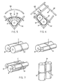
- FIGS 5 and 6 now show schematically (section transverse to the longitudinal conveying direction) two exemplary embodiments for belt devices, such as those in the discharge channel (32 in Figures 3 and 4) of merging points are provided.
- the individual packages brought together in the junction point are first pressed together and then wrapped around, so that two or more individual packages form a double or multiple package in which the packages are flattened at the contact surfaces and are therefore very stable in their mutual position.
- FIG. 5 shows a device, for example, for creating packages of three.
- a concavely curved press beam 50 is moved from a rest position shown in dash-dotted lines in the direction of the arrow against the discharge channel 32 into a press position shown in solid lines.
- the packages lying in the channel 32 are pressed against one another between the discharge channel 32 and the press bar 50 and in this state are wrapped around at least once by the wrap means 51, for example a cord or plastic band.
- the wrap means 51 for example a cord or plastic band.
- Devices for attaching the wrapping means 51 are known from wrapping stacked packages. For this reason, a representation of a corresponding device and an associated description will be omitted here.
- FIG. 6 shows a further embodiment of a device for creating double or multiple packages.
- This has two essentially flat press bars 61 and 62, one (61) having the function of stabilizing the packets in the position shown and the other (62) having the actual press function in the position of the individual packs shown. It is also quite conceivable that the two press bars 61 and 62 are joined together to form an angled single press bar.
- the two pressing beams 61 and 62 are also moved from a rest position (shown in broken lines) to a pressing position (shown in solid lines).
- FIG. 7 shows some examples of double or multiple packages which are formed by combining two or more single packages with the aid of a belt means 51.
- the flattened contact areas between the individual packages are visible.
- the wrapping means does not lie on the packages at the points labeled C, so that the package can be grasped and lifted at these points with a hook or by hand.
- Figure 8 shows schematically a device for a distribution point VU. It is a cut perpendicular to the longitudinal conveying direction.
- the figure shows a V-shaped conveying channel 80 in which packets P are conveyed into the distribution point in the longitudinal conveying direction (perpendicular to the paper plane).
- the conveyor channel 80 can be, for example, an exit channel from a package-producing device, a discharge channel of a merging point (32, FIG. 3) or the extension of the supply channel of a merging point (31, FIG. 3).
- the conveying channel 80 which is continued from the distribution point VU, can again lead into a merging point (Z / ZU) or into a further deflection point or distribution point (U / VU).
- the conveyor channel 80 has, for example, a wall part 81.1 and 81.2 that can be folded down on both sides (shown in dash-dot lines in the folded position), which allows a package to be laterally placed on a transverse conveyor (conveying direction FP q ), for example on a conveyor belt 40 or an equivalent to roll sloping taxiway.
- the wall of the conveying channel 80 is closed on one side, permanently open on the other side, and only on this latter side is a transverse conveying means connected.
- the parcels are led from the transverse conveying means adjoining a distribution or deflection point to an assembly point ZU (see FIGS. 2 and 4) or to a loading or intermediate storage point.
- the conveyor belts 40 can also be missing as cross-conveying means, so that the folded-down wall parts 81.1 and 82.2 (shown in dash-dotted lines) of the deflection or distribution points represent the only cross-conveying means to which a junction point ZU or loading is directly - or connect intermediate storage point.
- FIGS. 9 and 10 now show an exemplary embodiment of a device 90 for tilting packages into a position standing on an end face, as can be done according to the method according to the invention for loading or intermediate storage.
- the device is shown in FIG. 9 with a viewing angle perpendicular to the transverse conveying direction FP q , in FIG. 10 perpendicular to the transverse conveying direction FP q .
- the device is used for tipping packages occurring in the transverse conveying direction FP q , that is to say on a transverse conveying means or directly from a deflection point U or distribution point VU (as shown).
- tilt packets delivered in the longitudinal conveying direction they can simply be conveyed using appropriate tilting templates, by means of which they are brought into a position with a vertical axis.
- FIG. 11 shows tubular single / double and / or multiple packages P / PP which are temporarily stored on a pallet or stacked for transport. Such formations are very stable, even if they contain packages with small diameters, but which are integrated in a double or multiple package.
Landscapes
- Engineering & Computer Science (AREA)
- Mechanical Engineering (AREA)
- Coupling Device And Connection With Printed Circuit (AREA)
- Piles And Underground Anchors (AREA)
- Nitrogen Condensed Heterocyclic Rings (AREA)
- Auxiliary Devices For And Details Of Packaging Control (AREA)
- Discharge Of Articles From Conveyors (AREA)
- Stacking Of Articles And Auxiliary Devices (AREA)
- Basic Packing Technique (AREA)
- Discharge By Other Means (AREA)
Applications Claiming Priority (2)
| Application Number | Priority Date | Filing Date | Title |
|---|---|---|---|
| CH2195/92 | 1992-07-13 | ||
| CH219592 | 1992-07-13 |
Publications (2)
| Publication Number | Publication Date |
|---|---|
| EP0583218A1 true EP0583218A1 (fr) | 1994-02-16 |
| EP0583218B1 EP0583218B1 (fr) | 1997-03-05 |
Family
ID=4228113
Family Applications (1)
| Application Number | Title | Priority Date | Filing Date |
|---|---|---|---|
| EP93810359A Expired - Lifetime EP0583218B1 (fr) | 1992-07-13 | 1993-05-14 | Procédé et dispositif pour transporter des paquets tubulaires de produits imprimés et leur assemblage comme unités d'expédition |
Country Status (8)
| Country | Link |
|---|---|
| US (1) | US5419098A (fr) |
| EP (1) | EP0583218B1 (fr) |
| JP (1) | JPH06115698A (fr) |
| AT (1) | ATE149471T1 (fr) |
| AU (1) | AU665252B2 (fr) |
| DE (1) | DE59305570D1 (fr) |
| FI (1) | FI933186A (fr) |
| RU (1) | RU2114042C1 (fr) |
Cited By (1)
| Publication number | Priority date | Publication date | Assignee | Title |
|---|---|---|---|---|
| DE19605783A1 (de) * | 1996-02-16 | 1997-08-21 | Heinrich Schnell | Automatische Rollentransport-, Verpackungs-, und Sortieranlage für Endaufmachung, Prozeßgesteuert |
Families Citing this family (5)
| Publication number | Priority date | Publication date | Assignee | Title |
|---|---|---|---|---|
| US5885733A (en) * | 1994-07-07 | 1999-03-23 | Ricoh Company, Ltd. | Non-aqueous secondary lithium battery |
| US5713179A (en) * | 1994-09-30 | 1998-02-03 | Dai Nippon Printing Co. Ltd. | Combination of sheet roll with subshaft, producing apparatus thereof, packaging apparatus thereof, and production system thereof |
| FI107441B (fi) * | 1998-10-20 | 2001-08-15 | Metso Paper Inc | Menetelmä ja sovitelma rullaryhmän muodostamiseksi |
| JP2009543747A (ja) * | 2006-07-17 | 2009-12-10 | ア.チエリ ノンヴオヴエンス ソチエタ ペル アチオーニ | ウェブ素材のロールを生産し管理する自動化システム及び特に該システム用のロボット |
| USD861484S1 (en) | 2018-07-24 | 2019-10-01 | Kimberly-Clark Worldwide, Inc. | Bundle of consumer goods |
Citations (1)
| Publication number | Priority date | Publication date | Assignee | Title |
|---|---|---|---|---|
| EP0474999A1 (fr) * | 1990-08-28 | 1992-03-18 | Ferag AG | Procédé pour traiter des produits imprimés arrivant en formation d'écailles de poisson |
Family Cites Families (17)
| Publication number | Priority date | Publication date | Assignee | Title |
|---|---|---|---|---|
| US2701938A (en) * | 1951-11-30 | 1955-02-15 | Arthur J Murray | Method and apparatus for packaging cans and bottles in carrier cartons |
| US3537226A (en) * | 1967-10-27 | 1970-11-03 | Du Pont | Process of packaging batts of fibers |
| US3701314A (en) * | 1970-09-21 | 1972-10-31 | Hoerner Waldorf Corp | Strapping apparatus |
| US3818674A (en) * | 1970-09-21 | 1974-06-25 | Waldorf Corp | Bale wrapping apparatus |
| JPS4885858U (fr) * | 1972-01-19 | 1973-10-18 | ||
| JPS527652Y2 (fr) * | 1972-09-25 | 1977-02-17 | ||
| JPS535338Y2 (fr) * | 1973-02-28 | 1978-02-09 | ||
| JPS5532173Y2 (fr) * | 1975-02-08 | 1980-07-31 | ||
| JPS6015522B2 (ja) * | 1980-08-15 | 1985-04-19 | 有限会社比奈鉄工所 | トイレットペ−パ−ロ−ルの包装装置 |
| JPS57180505A (en) * | 1981-04-30 | 1982-11-06 | Kawasaki Steel Corp | Disc feeder for storing shelf |
| JPS5899327A (ja) * | 1981-12-10 | 1983-06-13 | 川之江造機株式会社 | 物品取り分け整列方法及び装置 |
| JPS6135113U (ja) * | 1984-07-31 | 1986-03-04 | 株式会社 石津製作所 | ロ−ル袋詰製品の連続製造装置 |
| FI72475C (fi) * | 1985-02-08 | 1987-06-08 | Waertsilae Oy Ab | Foerfarande foer anordning av rullar, i synnerhet pappersrullar till en foerpackning laemplig foer leverans. |
| CH680509A5 (fr) * | 1986-11-21 | 1992-09-15 | Ferag Ag | |
| JPH0738260Y2 (ja) * | 1988-08-25 | 1995-08-30 | 第一工業株式会社 | コンベヤによる物品仕分装置 |
| US5038549A (en) * | 1989-04-06 | 1991-08-13 | John E. Nordstrom | Stacking packaging machine |
| DE4015935C2 (de) * | 1990-05-17 | 1997-07-24 | Ferdinand Christ | Kommissioniervorrichtung für Artikel |
-
1993
- 1993-05-14 EP EP93810359A patent/EP0583218B1/fr not_active Expired - Lifetime
- 1993-05-14 AT AT93810359T patent/ATE149471T1/de not_active IP Right Cessation
- 1993-05-14 DE DE59305570T patent/DE59305570D1/de not_active Expired - Fee Related
- 1993-05-24 AU AU38764/93A patent/AU665252B2/en not_active Ceased
- 1993-05-28 US US08/069,019 patent/US5419098A/en not_active Expired - Fee Related
- 1993-06-23 JP JP5152297A patent/JPH06115698A/ja active Pending
- 1993-07-12 RU RU93035830A patent/RU2114042C1/ru active
- 1993-07-13 FI FI933186A patent/FI933186A/fi unknown
Patent Citations (1)
| Publication number | Priority date | Publication date | Assignee | Title |
|---|---|---|---|---|
| EP0474999A1 (fr) * | 1990-08-28 | 1992-03-18 | Ferag AG | Procédé pour traiter des produits imprimés arrivant en formation d'écailles de poisson |
Cited By (1)
| Publication number | Priority date | Publication date | Assignee | Title |
|---|---|---|---|---|
| DE19605783A1 (de) * | 1996-02-16 | 1997-08-21 | Heinrich Schnell | Automatische Rollentransport-, Verpackungs-, und Sortieranlage für Endaufmachung, Prozeßgesteuert |
Also Published As
| Publication number | Publication date |
|---|---|
| AU665252B2 (en) | 1995-12-21 |
| DE59305570D1 (de) | 1997-04-10 |
| FI933186A0 (fi) | 1993-07-13 |
| AU3876493A (en) | 1994-01-20 |
| US5419098A (en) | 1995-05-30 |
| RU2114042C1 (ru) | 1998-06-27 |
| EP0583218B1 (fr) | 1997-03-05 |
| FI933186A (fi) | 1994-01-14 |
| JPH06115698A (ja) | 1994-04-26 |
| ATE149471T1 (de) | 1997-03-15 |
Similar Documents
| Publication | Publication Date | Title |
|---|---|---|
| EP2174895B1 (fr) | Dispositif et procédé économique de formation de couches de conteneurs | |
| DE2952624A1 (de) | Vorrichtung zum gruppieren von gegenstaenden in stapelschichten zur beschickung von paletten | |
| AT394021B (de) | Vorrichtung zum foerdern von gegenstaenden | |
| DE2037911A1 (de) | Verfahren zum Aufstapeln von Vorzugs weise zusammengefalteten Schachteln o dgl und Vorrichtung zur Durchfuhrung des Ver fahrens | |
| EP0272398A1 (fr) | Dispositif pour transférer des produits imprimés arrivant en une ligne vers la ligne d'alimentation d'une station de transformation | |
| EP0583218B1 (fr) | Procédé et dispositif pour transporter des paquets tubulaires de produits imprimés et leur assemblage comme unités d'expédition | |
| DE19904443A1 (de) | Verfahren und Vorrichtung zum Zuführen von Packungszuschnitten | |
| DE19920531C2 (de) | Verpackungsstraße für Zeitschriften, Magazine und dergleichen Druckprodukte | |
| EP1439143A1 (fr) | Méthode et dispositif pour former des piles de produits d'imprimerie, comprenant une feuille additionnelle | |
| DE102005045864B4 (de) | Verpackungsanlage und Verpackungsverfahren | |
| EP0230677B1 (fr) | Dispositif et procédé de traitement d'imprimés tels que journaux, périodiques ou similaires, alimentés en courants d'articles se chevauchant | |
| EP0243753A1 (fr) | Procédé et dispositif pour traiter des produits imprimés, comme journaux, magazines et analogues, arrivant en formation imbriquée | |
| DE4209952C2 (de) | Einrichtung bei Buntaufteilanlagen | |
| EP3156250A1 (fr) | Procédé destiné à appliquer au moins un élément périphérique sur une combinaison de produits plats et dispositif d'application d'élément périphérique destiné à exécuter le procédé | |
| EP0870710B1 (fr) | Méthode et dispositif pour séparer et empiler du courant de transport des articles imprimés | |
| EP1564169B1 (fr) | Dispositif pour former des paquets de produits imprimés libres empilés | |
| DE3242192C2 (de) | Vorrichtung zum Verpacken von flachen Gegenständen | |
| EP1494949B1 (fr) | Procede et dispositif pour acheminer a chaque fois une pluralite de produits partiels plats dans une unite de traitement ulterieur en serie | |
| DE102018126695A1 (de) | Verpackungsvorrichtung zur Ausstattung von Artikeln oder Artikelgruppierungen mit umhüllenden Umverpackungen, insbesondere zum Umwickeln von Artikeln mit dehnbarer Folie | |
| CH640800A5 (de) | Verfahren und einrichtung zum manipulieren von druckprodukten. | |
| AT398745B (de) | Einrichtung zum sortieren von unterschiedlichen, auf buntaufteilanlagen aus plattenförmigen werkstücken durch längs- und querschnitte gewonnene formatzuschnitte | |
| AT412154B (de) | Verfahren sowie anlage zum kommissionieren von flachem, insbesondere blattförmigem stückgut | |
| AT404464B (de) | Anlage zum abstapeln von plattenpaketen unterschiedlichen grundrisses | |
| DE202023000970U1 (de) | Vorrichtung zum Positionieren von Produkten in einer Verpackungslinie | |
| DE3306639A1 (de) | Maschine zum ent- und bepalettieren |
Legal Events
| Date | Code | Title | Description |
|---|---|---|---|
| PUAI | Public reference made under article 153(3) epc to a published international application that has entered the european phase |
Free format text: ORIGINAL CODE: 0009012 |
|
| AK | Designated contracting states |
Kind code of ref document: A1 Designated state(s): AT CH DE DK GB IT LI NL SE |
|
| 17P | Request for examination filed |
Effective date: 19940711 |
|
| 17Q | First examination report despatched |
Effective date: 19950906 |
|
| GRAG | Despatch of communication of intention to grant |
Free format text: ORIGINAL CODE: EPIDOS AGRA |
|
| GRAH | Despatch of communication of intention to grant a patent |
Free format text: ORIGINAL CODE: EPIDOS IGRA |
|
| GRAH | Despatch of communication of intention to grant a patent |
Free format text: ORIGINAL CODE: EPIDOS IGRA |
|
| GRAA | (expected) grant |
Free format text: ORIGINAL CODE: 0009210 |
|
| AK | Designated contracting states |
Kind code of ref document: B1 Designated state(s): AT CH DE DK GB IT LI NL SE |
|
| PG25 | Lapsed in a contracting state [announced via postgrant information from national office to epo] |
Ref country code: IT Free format text: LAPSE BECAUSE OF FAILURE TO SUBMIT A TRANSLATION OF THE DESCRIPTION OR TO PAY THE FEE WITHIN THE PRESCRIBED TIME-LIMIT;WARNING: LAPSES OF ITALIAN PATENTS WITH EFFECTIVE DATE BEFORE 2007 MAY HAVE OCCURRED AT ANY TIME BEFORE 2007. THE CORRECT EFFECTIVE DATE MAY BE DIFFERENT FROM THE ONE RECORDED. Effective date: 19970305 Ref country code: DK Effective date: 19970305 |
|
| REF | Corresponds to: |
Ref document number: 149471 Country of ref document: AT Date of ref document: 19970315 Kind code of ref document: T |
|
| REG | Reference to a national code |
Ref country code: CH Ref legal event code: NV Representative=s name: FREI PATENTANWALTSBUERO Ref country code: CH Ref legal event code: EP |
|
| GBT | Gb: translation of ep patent filed (gb section 77(6)(a)/1977) |
Effective date: 19970305 |
|
| REF | Corresponds to: |
Ref document number: 59305570 Country of ref document: DE Date of ref document: 19970410 |
|
| PG25 | Lapsed in a contracting state [announced via postgrant information from national office to epo] |
Ref country code: AT Free format text: LAPSE BECAUSE OF NON-PAYMENT OF DUE FEES Effective date: 19970514 |
|
| PG25 | Lapsed in a contracting state [announced via postgrant information from national office to epo] |
Ref country code: SE Effective date: 19970605 |
|
| PLBE | No opposition filed within time limit |
Free format text: ORIGINAL CODE: 0009261 |
|
| STAA | Information on the status of an ep patent application or granted ep patent |
Free format text: STATUS: NO OPPOSITION FILED WITHIN TIME LIMIT |
|
| 26N | No opposition filed | ||
| PGFP | Annual fee paid to national office [announced via postgrant information from national office to epo] |
Ref country code: GB Payment date: 20000512 Year of fee payment: 8 |
|
| PGFP | Annual fee paid to national office [announced via postgrant information from national office to epo] |
Ref country code: NL Payment date: 20000524 Year of fee payment: 8 |
|
| PG25 | Lapsed in a contracting state [announced via postgrant information from national office to epo] |
Ref country code: GB Free format text: LAPSE BECAUSE OF NON-PAYMENT OF DUE FEES Effective date: 20010514 |
|
| PG25 | Lapsed in a contracting state [announced via postgrant information from national office to epo] |
Ref country code: NL Free format text: LAPSE BECAUSE OF NON-PAYMENT OF DUE FEES Effective date: 20011201 |
|
| GBPC | Gb: european patent ceased through non-payment of renewal fee |
Effective date: 20010514 |
|
| NLV4 | Nl: lapsed or anulled due to non-payment of the annual fee |
Effective date: 20011201 |
|
| REG | Reference to a national code |
Ref country code: CH Ref legal event code: PFA Owner name: FERAG AG Free format text: FERAG AG#ZUERICHSTRASSE 74#CH-8340 HINWIL (CH) -TRANSFER TO- FERAG AG#PATENTABTEILUNG Z. H. MARKUS FELIX ZUERICHSTRASSE 74#8340 HINWIL (CH) |
|
| PGFP | Annual fee paid to national office [announced via postgrant information from national office to epo] |
Ref country code: CH Payment date: 20060419 Year of fee payment: 14 |
|
| PGFP | Annual fee paid to national office [announced via postgrant information from national office to epo] |
Ref country code: DE Payment date: 20060519 Year of fee payment: 14 |
|
| REG | Reference to a national code |
Ref country code: CH Ref legal event code: PL |
|
| PG25 | Lapsed in a contracting state [announced via postgrant information from national office to epo] |
Ref country code: LI Free format text: LAPSE BECAUSE OF NON-PAYMENT OF DUE FEES Effective date: 20070531 Ref country code: CH Free format text: LAPSE BECAUSE OF NON-PAYMENT OF DUE FEES Effective date: 20070531 |
|
| PG25 | Lapsed in a contracting state [announced via postgrant information from national office to epo] |
Ref country code: DE Free format text: LAPSE BECAUSE OF NON-PAYMENT OF DUE FEES Effective date: 20071201 |