EP0581227B1 - Dispositif pour l'enregistrement et/ou la reproduction de signaux vidéo - Google Patents
Dispositif pour l'enregistrement et/ou la reproduction de signaux vidéo Download PDFInfo
- Publication number
- EP0581227B1 EP0581227B1 EP93111922A EP93111922A EP0581227B1 EP 0581227 B1 EP0581227 B1 EP 0581227B1 EP 93111922 A EP93111922 A EP 93111922A EP 93111922 A EP93111922 A EP 93111922A EP 0581227 B1 EP0581227 B1 EP 0581227B1
- Authority
- EP
- European Patent Office
- Prior art keywords
- video signal
- control signal
- recording
- signal
- digital
- Prior art date
- Legal status (The legal status is an assumption and is not a legal conclusion. Google has not performed a legal analysis and makes no representation as to the accuracy of the status listed.)
- Expired - Lifetime
Links
Images


Classifications
-
- G—PHYSICS
- G11—INFORMATION STORAGE
- G11B—INFORMATION STORAGE BASED ON RELATIVE MOVEMENT BETWEEN RECORD CARRIER AND TRANSDUCER
- G11B20/00—Signal processing not specific to the method of recording or reproducing; Circuits therefor
- G11B20/00086—Circuits for prevention of unauthorised reproduction or copying, e.g. piracy
-
- H—ELECTRICITY
- H04—ELECTRIC COMMUNICATION TECHNIQUE
- H04N—PICTORIAL COMMUNICATION, e.g. TELEVISION
- H04N5/00—Details of television systems
- H04N5/76—Television signal recording
- H04N5/91—Television signal processing therefor
- H04N5/913—Television signal processing therefor for scrambling ; for copy protection
-
- H—ELECTRICITY
- H04—ELECTRIC COMMUNICATION TECHNIQUE
- H04N—PICTORIAL COMMUNICATION, e.g. TELEVISION
- H04N5/00—Details of television systems
- H04N5/76—Television signal recording
- H04N5/91—Television signal processing therefor
- H04N5/92—Transformation of the television signal for recording, e.g. modulation, frequency changing; Inverse transformation for playback
- H04N5/9201—Transformation of the television signal for recording, e.g. modulation, frequency changing; Inverse transformation for playback involving the multiplexing of an additional signal and the video signal
- H04N5/9206—Transformation of the television signal for recording, e.g. modulation, frequency changing; Inverse transformation for playback involving the multiplexing of an additional signal and the video signal the additional signal being a character code signal
-
- H—ELECTRICITY
- H04—ELECTRIC COMMUNICATION TECHNIQUE
- H04N—PICTORIAL COMMUNICATION, e.g. TELEVISION
- H04N5/00—Details of television systems
- H04N5/76—Television signal recording
- H04N5/91—Television signal processing therefor
- H04N5/913—Television signal processing therefor for scrambling ; for copy protection
- H04N2005/91307—Television signal processing therefor for scrambling ; for copy protection by adding a copy protection signal to the video signal
- H04N2005/91314—Television signal processing therefor for scrambling ; for copy protection by adding a copy protection signal to the video signal the copy protection signal being a pulse signal inserted in blanking intervals of the video signal, e.g. pseudo-AGC pulses, pseudo-sync pulses
-
- H—ELECTRICITY
- H04—ELECTRIC COMMUNICATION TECHNIQUE
- H04N—PICTORIAL COMMUNICATION, e.g. TELEVISION
- H04N5/00—Details of television systems
- H04N5/76—Television signal recording
- H04N5/91—Television signal processing therefor
- H04N5/913—Television signal processing therefor for scrambling ; for copy protection
- H04N2005/91307—Television signal processing therefor for scrambling ; for copy protection by adding a copy protection signal to the video signal
- H04N2005/91321—Television signal processing therefor for scrambling ; for copy protection by adding a copy protection signal to the video signal the copy protection signal being a copy protection control signal, e.g. a record inhibit signal
-
- H—ELECTRICITY
- H04—ELECTRIC COMMUNICATION TECHNIQUE
- H04N—PICTORIAL COMMUNICATION, e.g. TELEVISION
- H04N5/00—Details of television systems
- H04N5/76—Television signal recording
- H04N5/91—Television signal processing therefor
- H04N5/913—Television signal processing therefor for scrambling ; for copy protection
- H04N2005/91307—Television signal processing therefor for scrambling ; for copy protection by adding a copy protection signal to the video signal
- H04N2005/91328—Television signal processing therefor for scrambling ; for copy protection by adding a copy protection signal to the video signal the copy protection signal being a copy management signal, e.g. a copy generation management signal [CGMS]
Definitions
- the present invention relates to a recording apparatus and a reproducing apparatus which are adapted to record/reproduce a video signal by converting it into a digital signal and more particularly to an apparatus suitable for limiting copy or copying of software (the contents of a recorded recording medium).
- the aforementioned conventional technique is for causing the gain control circuit of the recording apparatus to erroneously operate to thereby obtain an unsatisfactory recording result but essentially, it does not inhibit recording operation completely and therefore the results of copy or copying of software inhibited from being copied depend on the performance of the recording apparatus to some extent. Further, the presence or absence of the false synchronization pulse can in effect permit a simple limitation on copying but failed to take care of software which is scheduled to be copied permissibly only once but is inhibited from undergoing the second and ensuing copy operations (namely, in the case where the number of copy operations is limited).
- JP-A-2-89255 discloses a digital audio tape recorder (DAT) wherein a copy control signal of two bits indicative of permission/inhibition of copy is added to a digital audio signal, the permission/inhibition of copy of the digital audio signal and a limitation on the number of copy operations are decided on the basis of the copy control signal, and control of copy of the digital audio signal is executed in accordance with a result of the decision.
- DAT digital audio tape recorder
- EP-A-0 328 141 discloses a recording and reproducing apparatus wherein a composite digital signal received by the recording and reproducing apparatus includes a digital information signal and a control signal.
- the control code is only used during recording and reproduction of digital audio signals. No control code signal is used in an analog audio signal.
- EP-A-0 422 849 discloses a digital recording and reproducing apparatus comprising a digital copy permissibility decision portion for deciding whether a digital copy is permissible or not.
- EP-A-0 256 753 comprises a method and an apparatus for preventing the copying of video program to which a plurality of ordered pairs of pseudo-sync and positive pulses are added to the video signal vertical blanking interval following the normal sync pulse.
- WO-A-92/00649 discloses a dual deck video cassette recorder with copy prevention in which also pseudo-sync pulses are added during the vertical blanking time.
- An object of the present invention is to provide a recording apparatus and a reproducing apparatus for video signals wherein a control signal relating to a video signal to be recorded or reproduced is added to the video signal in advance, and during recording or reproduction of the video signal, the control signal is detected and it is added to the video signal so as to be recorded or reproduced after being changed as necessary.
- This object is achieved by means of a video signal reproducing apparatus and a video signal recording apparatus as defined in claims 1 and 6, respectively.
- the control signal may include copy information concerning permission/inhibition of copying of a video signal or a limitation on the number of copy operations, program information for indicating the total time, lapse time, residual time and title of video software or image processing information indicative of a compression processing system used when the video signal is subjected to a compression processing.
- the control signal may be formed of a plurality of bits and is preferably inserted during the blanking period of the video signal but for a digital video signal, it may be positioned in front of a video signal field.
- copy information is added to a reproduction video signal output during reproduction in compliance with the contents of copy information added in advance to a reproduction video signal from a recording medium.
- copy information in an inputted video signal is detected and permission/inhibition of copy (record) of the input video signal is controlled on the basis of the detected copy information.
- suitably generated copy information is added to a video signal to be recorded in compliance with the presence or absence of copy information added in advance to the input video signal or the contents of the copy information. In this manner, the limitation on the number of copy operations can be dealt with and highly reliable copy control can be ensured.
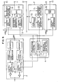
- Fig. 1 is a block diagram showing an essential construction of a digital video recording/reproducing apparatus (digital VTR) according to an embodiment of the present invention.
- 1 designates a rotary head for recording/reproducing a video signal on/from a magnetic tape 14, 2 a recording/reproducing circuit for performing generation of a recording signal during recording and detection of data during reproduction, 3 a video signal processing circuit for performing compression and expansion of a video signal and the like processing, 4 a recording/reproducing control circuit for controlling recording/reproducing operation, 5 a digital interface circuit (hereinafter referred to as an interface circuit) for performing input/output operation of a digital video signal, 6 an A/D conversion circuit for converting an analog video signal into a digital signal, 7 a control signal detection circuit for detecting a control signal contained in the analog video signal, 8 a D/A conversion circuit for converting a digital video signal into an analog signal, 9 a control signal generator for adding the control signal to the analog video signal, 10 an input terminal of a digital video signal, 11 an
- the control signal contains copy information.
- the video signal inputted from the input terminal 12 is converted by the A/D converter 6 into a digital signal and the digital signal is inputted to the video signal processing circuit 3.
- the digital signal is then subjected to compression and the like processing, added with an error correction code, control information and the like at the recording/reproducing circuit 2 and recorded on the magnetic tape 14 by means of the rotary head 1.
- copy information contained in the analog video signal is detected and outputted to the recording/reproducing control circuit 4.
- the recording/reproducing control circuit 4 decides permission/inhibition of copy in accordance with the contents of the copy information or the presence or absence of copy information and when determining permissibility of copy, it generates copy information to be recorded on the magnetic tape 14.
- the recording/reproducing control circuit 4 determines the permissibility of copy, it causes the recording/reproducing circuit 2 to record the video signal together with the generated copy information added thereto on the magnetic tape 14 but when the recording/reproducing control circuit 4 has determined inhibition of copy, it inhibits the recording/reproducing circuit 2 from performing recording operation per se.
- the digital signal inputted from the input terminal 10 is applied to the interface circuit 5.
- the interface circuit 5 separates a video signal and detects a control signal from the input signal. Then, the video signal is inputted to the video signal processing circuit 3 and the control signal is inputted to the recording/reproducing control circuit 4.
- the recording/reproducing control circuit 4 also decides permission/inhibition of copy in accordance with the contents of the control signal including copy information and when determining permissibility of copy, it generates copy information to be recorded on the magnetic tape 14.
- the recording/reproducing circuit 2 records the video signal together with the copy information, generated by the recording/reproducing control circuit and added to the video signal, on the magnetic tape 14 but with inhibition of copy determined, the recording/reproducing control circuit 4 is inhibited from performing recording operation per se.
- a signal reproduced from the magnetic tape 14 by means of the rotary head 1 is inputted to the recording/reproducing circuit 2.
- the recording/reproducing circuit 2 error correction, detection of a control signal and the like are carried out.
- a video signal is inputted to the video signal processing circuit 3 so as to undergo expansion and the like processing and thereafter it is delivered to the interface circuit 5 and D/A conversion circuit 8.
- the control signal (containing at least copy information) is inputted to the recording/reproducing control circuit 4.
- the recording/reproducing control circuit 4 decides the contents of the copy information reproduced from the magnetic tape 14 and it generates, in accordance with that contents, copy information (control signal) to be added to a video signal output.
- a digital video signal delivered out of the video signal processing circuit 3 is added with the copy information (control signal containing copy information) generated from the recording/reproducing control circuit 4 and is delivered through the output terminal 11.
- an analog video signal delivered out of the D/A conversion circuit 8 is added with the copy information generated from the recording/reproducing control circuit 4 and is delivered through the output terminal 13.
- recording/reproducing is controlled by a technique using the copy information, and an example of the technique will be described below.
- the aforementioned copy information is of 2 bits wherein "00" is recorded for the case that copy of software or the like prepared by the user need not be limited, "01” is recorded for the case that copy is not at all permitted and "11” is recorded for the case that copy is permitted only once.
- a digital video signal and an analog video signal are each added with something equivalent to copy information detected from a reproduction signal and are then delivered.
- recording is controlled in accordance with copy information added to an inputted digital video signal or analog video signal.
- copy information in an input signal is "00”
- recording is effected by rendering copy information to be recorded also to be “00”.
- copy information is "11"(when copy is permitted to be done only once)
- recording is effected by rewriting copy information to be recorded to "10".
- a timing clock generation circuit used conventionally in general is included in the circuit system shown in Fig. 1 and operation timing of each circuit block is controlled by a timing pulse generated from the generation circuit.
- Fig. 2 shows an example of a digital input/output signal.
- the digital input/output signal is formatted in a unit of block and one block consists of a synchronization code 15, a control code 16 and a video signal 17.
- the control code 16 then consists of the above-described copy information of 2 bits and other information recorded together with the video signal.
- the video signal 17 is formed of a digital video signal of a plurality of words. If a compressed signal is used as the video signal, then the transmission rate of the digital input/output signal can be decreased. In this case, information about a compression system may be included in the control code. Further, if the signal of Fig.
- Fig. 3 shows an example of an analog input/output signal at the time of a vertical blanking period.
- 18 designates a horizontal synchronizing pulse and 19 a control signal.
- the vertical blanking period is a portion which is not displayed on the screen and in which an ordinary analog video signal takes a non-signal state.
- the control signal such as the above-described copy information of 2 bits, can be transmitted even when an image is transmitted in the form of an analog signal.
- Fig. 4 shows an example of addition of copy information as control information of an analog input/output signal.
- 20 and 23 designate synchronizing signals and 21 and 22 copy information.
- the copy information is of 2 bits and ability to detect it is improved by adding the synchronizing signals before and after the copy information. If the copy information is written in multiplex fashion over a few lines, detection ability can further be improved.
- Fig. 5 shows another example of addition of copy information as control information of an analog input/ output signal.
- copy information is added in the form of a signal similar to the false synchronization pulse described in the aforementioned JP-A-61-288582.
- copy can be limited even when recording is effected with an ordinary analog video tape recorder.
- the control signal detection circuit 7 is designed so as to be capable of also detecting the false synchronization pulse, copy can also be limited in the case that a video signal reproduced by the analog video tape recorder is recorded.
- Fig. 6 is a block diagram showing, in greater detail, circuit components relating to the flow of the control code or signal. Referring to Fig. 6, a description will be given by taking the aforementioned copy information of 2 bits, for instance.
- the analog video signal as shown in Fig. 4 is inputted from the input terminal 12 and supplied to the control signal detection circuit 7.
- a synchronization signal detection circuit 71 detects horizontal synchronizing signals 18 associated with the vertical blanking period of the inputted video signal and generates timing pulses at timings of 2-bit copy information 21, 22 by utilizing synchronizing signals 20 and 23 in Fig. 4 through a wellknown method.
- a level comparison circuit 72 compares the input video signal with a threshold level as shown at chained line in Fig. 4 to deliver a high level when the video signal level exceeds the threshold level. Responsive to the timing pulses from the synchronization signal detection circuit 71, a control signal register 73 takes in the output level of the level comparison circuit 72 as copy information and transfers the copy information to the recording/reproducing control circuit 4.
- a recording/reproducing mode setting circuit 41 sends a recording command signal and a reproduction command signal to a recording control circuit 42 and a reproduction control circuit 43, respectively.
- the recording control circuit 42 transfers, when the inputted copy information assumes "00" to indicate that recording is not limited, "00" as it is but when the copy information assumes "11” to indicate that copy is permitted to be effected only once, it converts "11" into “10” to transfer the same to the recording/reproducing circuit 2.
- the recording control circuit 42 releases the recording mode of the recording/reproducing mode setting circuit 41 in spite of the fact that the recording command signal is inputted, thereby preventing execution of recording operation.
- control signal generator 25 has the same construction as that of a digital video signal generation section of interface circuit 5 to be described later and will be understood from a description to be given of that section hereinafter.
- the digital video signal inputted from the input terminal 10 is applied to a synchronization code detection circuit 51.
- This circuit 51 detects a synchronization code 15 of Fig. 2 and on the basis of the detected synchronization code, it generates a timing signal timed to the presence of copy information in a control code 16 through the use of a wellknown method.
- a control code register 52 takes in the 2-bit copy information and delivers it to the recording control circuit 42. After that, the recording/reproducing control circuit 4 and recording/reproducing circuit 2 operate in the same manner as described previously.
- a digital video signal reproduced from the magnetic tape 14 is inputted to the recording/reproducing circuit 2, and copy information is detected by means of a control code detection circuit 26 and supplied to the recording/reproducing control circuit 4.
- the inputted copy information is applied to the control signal generator 9 and interface circuit 5 through the reproduction control circuit 43.
- the inputted copy information is converted into a signal level matching an analog signal by means of a control signal generation circuit 91 and is then supplied to an adder circuit 92.
- the adder circuit 92 adds the copy information together with synchronizing signals to the video signal and delivers a resulting signal to the output terminal 13.
- the timings for the addition of the copy information to the video signal are controlled by a timing pulse for controlling the operation timing of the entire circuit system, which timing pulse is generated from the timing pulse generation circuit.
- the copy information is temporarily held in a control code register 53.
- a synchronization code generation circuit 54 generates a synchronization code as shown in Fig. 2 at a predetermined timing.
- a multiplexer 55 executes input switching control under the control of the timing pulse in order of the synchronization code from the synchronization code generation circuit 54, the copy information from the control code register 53 and the video signal from the video signal processing circuit 3, thereby generating a digital video signal as shown in Fig. 2 which is delivered to the digital output terminal 11.
- the multiplexer resembles the control signal generator 25 included in the recording/reproducing circuit 2.
- the video signal has been described as being added with the control information standing for the copy information but for a video signal not added with a control code or copy information, new copy information "00" may be generated on the assumption that copy information is, for example, "00" and it may be added to the video signal.
- a false synchronization pulse is inserted during the vertical blanking period
- the copy information is processed in accordance with the procedure described on the basis of Fig. 6 but when the false synchronization pulse is not detected, "00" is generated as copy information and can be inserted in a video signal. In this manner, exchangeability with conventional tape recorders can be maintained.
- the present invention may also be applied to an apparatus dedicated to recording or an apparatus dedicated to reproduction.
- Information other than the copy information can be transmitted as the control signal.
- program information or the like recorded by being added to a video signal may be transmitted by being added to an analog video signal during copying, and a control signal to be recorded may be generated by using that information. In this manner, control information can be copied even in copy by analog video signals.
Claims (13)
- Dispositif de lecture de signal vidéo ayant un agencement de générateur de signal de commande, ledit dispositif comportant :des moyens de lecture (1) pour lire un signal vidéo numérique enregistré sur un support d'enregistrement (14), et délivrer en sortie un signal vidéo numérique (11) et un signal vidéo analogique (13) dans lequel ledit signal vidéo numérique lu est converti par un convertisseur N/A (8),des moyens de détection de signal de commande (26) pour détecter un signal de commande numérique contenu dans ledit signal vidéo numérique lu, ledit signal de commande numérique commandant une condition d'enregistrement concernant ledit signal vidéo numérique,un circuit de commande de lecture (43) pour délivrer le contenu d'informations dudit signal de commande numérique détecté à des moyens de génération d'un premier signal de commande (91) pour générer un premier signal de commande numérique (21, 22) à ajouter audit signal vidéo analogique de sortie et à des moyens de génération d'un second signal de commande (53, 54) pour générer un second signal de commande numérique (16) à ajouter audit signal vidéo numérique de sortie, lesdits premier et second signaux de commande numériques commandant une condition d'enregistrement ultérieure desdits signaux vidéo délivrés en sortie, ladite condition d'enregistrement étant imposée par le contenu d'informations desdits premier et second signaux de commande numériques,des premiers moyens additionneurs (92) pour ajouter ledit premier signal de commande numérique (21, 22) à une partie d'une période de suppression de trame dudit signal vidéo analogique de sortie pour produire un signal vidéo analogique de sortie (13) ayant ledit premier signal de commande numérique, etdes seconds moyens additionneurs (55) pour ajouter ledit second signal de commande numérique (16) audit signal vidéo numérique de sortie pour produire un signal vidéo numérique de sortie (11) ayant ledit second signal de commande numérique.
- Dispositif de lecture de signal vidéo selon la revendication 1, dans lequel lesdits premier et second signaux de commande numériques comportent des informations de copie indicatives d'une autorisation/interdiction de copie dudit signal vidéo enregistré sur ledit support d'enregistrement.
- Dispositif de lecture de signal vidéo selon la revendication 2, dans lequel lesdites informations de copie contiennent des informations concernant au moins l'une parmi une interdiction de copie, une autorisation de copie et une limitation du nombre d'opérations de copie.
- Dispositif de lecture de signal vidéo selon la revendication 3, dans lequel ledit premier ou second signal de commande numérique a le même contenu d'informations que celui desdites informations de copie détectées par lesdits moyens de détection de signal de commande (26).
- Dispositif de lecture de signal vidéo selon la revendication 2, dans lequel ledit premier ou second signal de commande numérique est un signal indicatif d'une autorisation de copie lorsque lesdits moyens de détection de signal de commande (26) ne peuvent pas détecter lesdites informations de copie à partir dudit signal vidéo lu par lesdits moyens de lecture.
- Dispositif d'enregistrement de signal vidéo ayant un agencement de générateur de signal de commande, comportant :des premiers moyens d'entrée (12) pour recevoir un signal vidéo analogique d'entrée,des seconds moyens d'entrée (10) pour recevoir un signal vidéo numérique d'entrée,des moyens de détection d'un premier signal de commande (7) pour détecter un premier signal de commande numérique (21, 22) contenu dans une période de suppression de trame dudit signal vidéo numérique d'entrée, etdes moyens de détection d'un second signal de commande (51, 52) pour détecter un second signal de commande numérique (16) contenu dans ledit signal vidéo numérique d'entrée, lesdits premier et second signaux de commande numériques commandant une condition d'enregistrement concernant lesdits signaux vidéo entrés,des moyens de reconstitution d'un signal de commande (42) pour former un signal de commande numérique reconstitué à partir desdits premier et second signaux de commande numériques, ledit signal de commande numérique reconstitué étant à ajouter à l'un parmi un signal vidéo numérique converti par un convertisseur A/N (6) à partir dudit signal vidéo analogique d'entrée et ledit signal vidéo numérique d'entrée pour commander une condition d'enregistrement ultérieure desdits signaux vidéo entrés, ladite condition d'enregistrement étant imposée par le contenu d'informations dudit signal de commande numérique reconstitué,des moyens additionneurs (25) pour ajouter, si l'enregistrement n'est pas interdit, ledit signal de commande numérique reconstitué à l'un parmi ledit signal vidéo numérique converti à partir dudit signal vidéo analogique d'entrée et ledit signal vidéo numérique d'entrée pour produire un signal d'enregistrement ayant ledit signal de commande numérique reconstitué, etdes moyens d'enregistrement (1) pour enregistrer ledit signal d'enregistrement sur un support d'enregistrement (14).
- Dispositif d'enregistrement de signal vidéo selon la revendication 6, dans lequel lesdits premier ou second signaux de commande numériques (16 ; 21, 22) comportent des informations de copie indicatives d'une autorisation/interdiction de copie dudit signal vidéo d'entrée entré par lesdits moyens d'entrée.
- Dispositif d'enregistrement de signal vidéo selon la revendication 7, dans lequel lesdites informations de copie contiennent des informations concernant au moins l'une parmi une interdiction de copie, une autorisation de copie et une limitation du nombre d'opérations de copie.
- Dispositif d'enregistrement de signal vidéo selon la revendication 8, dans lequel lorsque lesdites informations de copie sont des informations destinées à autoriser la copie, lesdits moyens de reconstitution de signal de commande forment ledit signal de commande numérique reconstitué en tant que code indicatif d'une autorisation de copie.
- Dispositif d'enregistrement de signal vidéo selon la revendication 8, dans lequel lorsque lesdites informations de copie sont des informations destinées à autoriser uniquement une opération de copie, lesdits moyens de reconstitution de signal de commande forment ledit signal de commande numérique reconstitué en tant que code indicatif d'une interdiction de copie.
- Dispositif d'enregistrement de signal vidéo selon la revendication 7, comportant en outre des moyens d'interdiction (41) pour interdire des opérations d'enregistrement desdits moyens d'enregistrement lorsque ledit premier ou second signal de commande numérique (16 ; 21, 22) détecté par lesdits moyens de détection de signal de commande contient des informations de copie indicatives d'une interdiction de copie.
- Dispositif d'enregistrement de signal vidéo selon la revendication 6, dans lequel lorsque lesdits moyens de détection de signal de commande ne peuvent pas détecter ledit premier ou second signal de commande (16 ; 21, 22) à partir dudit signal vidéo d'entrée entré par lesdits moyens d'entrée, lesdits moyens de reconstitution de signal de commande forment ledit signal de commande numérique reconstitué en tant que code indicatif d'une autorisation de copie.
- Dispositif d'enregistrement de signal vidéo selon la revendication 7, dans lequel si ledit signal vidéo analogique d'entrée contient non pas ledit premier signal de commande numérique (21, 22) mais une impulsion de synchronisation erronée insérée pour empêcher un enregistrement normal, les premiers moyens de détection de signal de commande (7) sont capables de détecter ladite impulsion de synchronisation erronée pour empêcher la copie.
Applications Claiming Priority (3)
| Application Number | Priority Date | Filing Date | Title |
|---|---|---|---|
| JP20141492A JP3217137B2 (ja) | 1992-07-28 | 1992-07-28 | 映像信号記録装置、再生装置及び伝送装置 |
| JP201414/92 | 1992-07-28 | ||
| JP20141492 | 1992-07-28 |
Publications (3)
| Publication Number | Publication Date |
|---|---|
| EP0581227A2 EP0581227A2 (fr) | 1994-02-02 |
| EP0581227A3 EP0581227A3 (fr) | 1994-03-09 |
| EP0581227B1 true EP0581227B1 (fr) | 2005-09-21 |
Family
ID=16440694
Family Applications (1)
| Application Number | Title | Priority Date | Filing Date |
|---|---|---|---|
| EP93111922A Expired - Lifetime EP0581227B1 (fr) | 1992-07-28 | 1993-07-26 | Dispositif pour l'enregistrement et/ou la reproduction de signaux vidéo |
Country Status (4)
| Country | Link |
|---|---|
| US (2) | US5627655A (fr) |
| EP (1) | EP0581227B1 (fr) |
| JP (1) | JP3217137B2 (fr) |
| DE (1) | DE69333873T2 (fr) |
Cited By (10)
| Publication number | Priority date | Publication date | Assignee | Title |
|---|---|---|---|---|
| US7730323B2 (en) | 1994-04-01 | 2010-06-01 | Makoto Saito | Controlling database copyrights |
| US7730324B2 (en) | 1994-04-01 | 2010-06-01 | Makoto Saito | Method for controlling database copyrights |
| USRE41657E1 (en) | 1994-10-27 | 2010-09-07 | Makoto Saito | Data management system |
| US7801817B2 (en) | 1995-10-27 | 2010-09-21 | Makoto Saito | Digital content management system and apparatus |
| US7827109B2 (en) | 1994-10-27 | 2010-11-02 | Makoto Saito | Digital content management system and apparatus |
| USRE42163E1 (en) | 1994-04-01 | 2011-02-22 | Intarsia Software Llc | Data management system |
| US7986785B2 (en) | 1994-10-27 | 2011-07-26 | Intarsia Software Llc | Data management |
| US8024810B2 (en) | 1998-10-15 | 2011-09-20 | Intarsia Software Llc | Method and apparatus for protecting digital data by double re-encryption |
| US8352373B2 (en) | 1994-09-30 | 2013-01-08 | Intarsia Software Llc | Data copyright management system |
| US8595502B2 (en) | 1995-09-29 | 2013-11-26 | Intarsia Software Llc | Data management system |
Families Citing this family (99)
| Publication number | Priority date | Publication date | Assignee | Title |
|---|---|---|---|---|
| JP3166346B2 (ja) * | 1992-10-08 | 2001-05-14 | ソニー株式会社 | 映像付加情報伝送方式 |
| US6424725B1 (en) | 1996-05-16 | 2002-07-23 | Digimarc Corporation | Determining transformations of media signals with embedded code signals |
| US7171016B1 (en) | 1993-11-18 | 2007-01-30 | Digimarc Corporation | Method for monitoring internet dissemination of image, video and/or audio files |
| US6983051B1 (en) | 1993-11-18 | 2006-01-03 | Digimarc Corporation | Methods for audio watermarking and decoding |
| US6944298B1 (en) | 1993-11-18 | 2005-09-13 | Digimare Corporation | Steganographic encoding and decoding of auxiliary codes in media signals |
| US6408082B1 (en) | 1996-04-25 | 2002-06-18 | Digimarc Corporation | Watermark detection using a fourier mellin transform |
| US6122403A (en) | 1995-07-27 | 2000-09-19 | Digimarc Corporation | Computer system linked by using information in data objects |
| US6449377B1 (en) | 1995-05-08 | 2002-09-10 | Digimarc Corporation | Methods and systems for watermark processing of line art images |
| US7313251B2 (en) * | 1993-11-18 | 2007-12-25 | Digimarc Corporation | Method and system for managing and controlling electronic media |
| US6614914B1 (en) | 1995-05-08 | 2003-09-02 | Digimarc Corporation | Watermark embedder and reader |
| US5768426A (en) | 1993-11-18 | 1998-06-16 | Digimarc Corporation | Graphics processing system employing embedded code signals |
| US6516079B1 (en) | 2000-02-14 | 2003-02-04 | Digimarc Corporation | Digital watermark screening and detecting strategies |
| US6757406B2 (en) | 1993-11-18 | 2004-06-29 | Digimarc Corporation | Steganographic image processing |
| US5748763A (en) | 1993-11-18 | 1998-05-05 | Digimarc Corporation | Image steganography system featuring perceptually adaptive and globally scalable signal embedding |
| US6611607B1 (en) | 1993-11-18 | 2003-08-26 | Digimarc Corporation | Integrating digital watermarks in multimedia content |
| JP3321972B2 (ja) * | 1994-02-15 | 2002-09-09 | ソニー株式会社 | ディジタル信号記録装置 |
| JP3329063B2 (ja) * | 1994-03-29 | 2002-09-30 | ソニー株式会社 | 再生装置 |
| DE69530622T2 (de) * | 1994-07-08 | 2004-02-26 | Sony Corp. | Empfang von zugangskontrollierten Rundfunksignalen |
| US5574787A (en) * | 1994-07-25 | 1996-11-12 | Ryan; John O. | Apparatus and method for comprehensive copy protection for video platforms and unprotected source material |
| US6560349B1 (en) | 1994-10-21 | 2003-05-06 | Digimarc Corporation | Audio monitoring using steganographic information |
| JP3072699B2 (ja) * | 1994-10-25 | 2000-07-31 | ソニー株式会社 | ディジタル映像装置 |
| JPH08263438A (ja) * | 1994-11-23 | 1996-10-11 | Xerox Corp | ディジタルワークの配給及び使用制御システム並びにディジタルワークへのアクセス制御方法 |
| KR0152788B1 (ko) | 1994-11-26 | 1998-10-15 | 이헌조 | 디지탈 영상 시스템의 복사 방지 방법 및 장치 |
| KR0136458B1 (ko) | 1994-12-08 | 1998-05-15 | 구자홍 | 디지탈 자기 기록재생 시스템의 복사 방지장치 |
| EP1555591B1 (fr) * | 1995-02-13 | 2013-08-14 | Intertrust Technologies Corp. | Procédé et dispositif de gestion de transactions sécurisées |
| JP3617115B2 (ja) * | 1995-03-31 | 2005-02-02 | ソニー株式会社 | ビデオ信号処理装置および処理方法 |
| JPH08287603A (ja) * | 1995-04-13 | 1996-11-01 | Pioneer Electron Corp | 情報記録装置及び情報再生装置 |
| US5699427A (en) * | 1995-06-23 | 1997-12-16 | International Business Machines Corporation | Method to deter document and intellectual property piracy through individualization |
| US6980653B1 (en) | 1995-07-21 | 2005-12-27 | Sony Corporation | Signal reproducing/recording/transmitting method and apparatus and signal record medium |
| JP3252706B2 (ja) * | 1995-07-21 | 2002-02-04 | ソニー株式会社 | 映像信号再生方法及び装置、並びに信号伝送方法及び装置 |
| US7065211B1 (en) * | 1995-07-21 | 2006-06-20 | Sony Corporation | Signal reproducing/recording/transmitting method and apparatus and signal recording medium |
| US6411725B1 (en) * | 1995-07-27 | 2002-06-25 | Digimarc Corporation | Watermark enabled video objects |
| US5703859A (en) * | 1995-09-01 | 1997-12-30 | Sony Corporation | Digital video copy protection system |
| ATE208113T1 (de) * | 1995-09-01 | 2001-11-15 | Sony Corp | Datenaufzeichnung mit kopierschutz |
| JPH0998375A (ja) * | 1995-09-29 | 1997-04-08 | Sony Corp | デジタル画像信号の記録方法、記録装置及び記録再生装置 |
| JP3850035B2 (ja) * | 1995-10-04 | 2006-11-29 | コーニンクレッカ フィリップス エレクトロニクス エヌ ヴィ | ディジタル符号化ビデオ及び/又はオーディオ信号のマーキング技術 |
| DE69625982T2 (de) * | 1995-10-18 | 2004-01-22 | Matsushita Electric Industrial Co., Ltd., Kadoma | Informationsaufzeichnungs- und ausgabevorrichtung |
| JP3613858B2 (ja) * | 1995-10-26 | 2005-01-26 | ソニー株式会社 | テレビジョン信号の伝送または記録方法、および記録装置 |
| CN1123221C (zh) * | 1995-12-11 | 2003-10-01 | 皇家菲利浦电子有限公司 | 标记视频和/或音频信号 |
| AU1344097A (en) * | 1996-01-03 | 1997-08-01 | Sony Electronics Inc. | Copy protect recording and playback system |
| JP3528394B2 (ja) * | 1996-01-23 | 2004-05-17 | ソニー株式会社 | データ記録再生装置 |
| EP0913999B1 (fr) | 1996-02-02 | 2005-10-05 | Thomson Consumer Electronics, Inc. | Procédé de gestion de copie |
| US6011765A (en) * | 1996-04-12 | 2000-01-04 | Sony Corporation | Recording medium having copying protection signals recorded in superposition on main signals |
| EP1796014A3 (fr) * | 1996-05-15 | 2011-05-25 | Intertrust Technologies Corp | Système et procédé pour la conversion de signaux analogiques en signaux numériques avec protection de la gestion des droits |
| US6381341B1 (en) | 1996-05-16 | 2002-04-30 | Digimarc Corporation | Watermark encoding method exploiting biases inherent in original signal |
| US5862299A (en) * | 1996-06-19 | 1999-01-19 | Sony Corporation | Conditional access system for local storage device |
| US6278836B1 (en) * | 1996-08-27 | 2001-08-21 | Matsushita Electric Industrial Co., Ltd. | Information reproducing apparatus for reproducing video signals and program information which are recorded in information recording media |
| JP3716511B2 (ja) * | 1996-09-02 | 2005-11-16 | ソニー株式会社 | ビデオ信号処理装置 |
| TW311999B (en) * | 1996-10-16 | 1997-08-01 | Ibm | Method of recording media data on recording media, accessing media data and system thereof |
| JP3736588B2 (ja) * | 1996-11-18 | 2006-01-18 | ソニー株式会社 | 情報出力装置、情報出力方法、記録装置および情報複製防止制御方法 |
| JP3594062B2 (ja) * | 1996-11-19 | 2004-11-24 | ソニー株式会社 | 情報伝送方法、情報出力装置および情報記録装置 |
| JPH10174070A (ja) * | 1996-12-10 | 1998-06-26 | Sony Corp | 映像信号伝送方法、重畳情報抽出方法、映像信号出力装置、映像信号記録装置および映像信号記録媒体 |
| WO1998033176A2 (fr) * | 1997-01-27 | 1998-07-30 | Koninklijke Philips Electronics N.V. | Systeme de protection contre la copie de signaux enregistres |
| KR100238082B1 (ko) * | 1997-04-14 | 2000-01-15 | 윤종용 | 복사모드를 자동으로 선택하는 복사장치 |
| US6356704B1 (en) | 1997-06-16 | 2002-03-12 | Ati Technologies, Inc. | Method and apparatus for detecting protection of audio and video signals |
| JPH11219566A (ja) * | 1997-11-28 | 1999-08-10 | Matsushita Electric Ind Co Ltd | ディジタルデータ再生装置および再生信号二値化レベル補正方法 |
| JPH11176091A (ja) * | 1997-12-15 | 1999-07-02 | Hitachi Ltd | ディジタル情報入出力装置、受信装置、記録装置、および再生装置 |
| US6137952A (en) * | 1998-04-02 | 2000-10-24 | Hewlett-Packard Company | Apparatus and method for degrading the quality of unauthorized copies of color images and video sequences |
| JP3201347B2 (ja) * | 1998-05-15 | 2001-08-20 | 日本電気株式会社 | 画像属性変更装置と電子透かし装置 |
| EP0999705B1 (fr) * | 1998-05-20 | 2010-04-28 | Sony Computer Entertainment Inc. | Dispositif et procede de traitement d'informations |
| JP3835655B2 (ja) * | 1998-06-09 | 2006-10-18 | ソニー株式会社 | 情報信号再生装置、情報信号処理装置、情報信号再生方法および情報信号出力方法 |
| JP2000069415A (ja) | 1998-08-18 | 2000-03-03 | Fujitsu Ltd | 画像制御回路、画像制御方法、又は、画像制御方法をコンピュータシステムに実行させるためのプログラムを記憶したコンピュータ読み取り可能な媒体 |
| US6778757B1 (en) * | 1998-10-23 | 2004-08-17 | Hitachi, Ltd. | Data recording/reproduction apparatus and method |
| EP1473721B1 (fr) | 1998-12-11 | 2015-07-15 | Sony Corporation | Méthode pour contrôler la copie de données |
| MY124066A (en) * | 1998-12-25 | 2006-06-30 | Sony Corp | Information processing device and method, and program storage medium. |
| JP4536260B2 (ja) * | 1999-01-21 | 2010-09-01 | ソニー株式会社 | データ処理装置及びデータ処理方法 |
| EP1147664A4 (fr) * | 1999-01-26 | 2003-06-25 | Macrovision Corp | Procede et dispositif permettant d'acheminer des donnees avec un signal video de maniere a ne pas enregistrer les donnees |
| US6950520B1 (en) | 1999-01-26 | 2005-09-27 | Macrovision Corporation | Method and apparatus for carrying data in a video signal so that the data is not recorded |
| CA2332034C (fr) * | 1999-03-15 | 2008-07-29 | Koninklijke Philips Electronics N.V. | Procede et systeme assurant la protection contre la copie sur un support memoire et support memoire destine a etre utilise dans un tel systeme |
| JP2000324468A (ja) | 1999-05-14 | 2000-11-24 | Sony Corp | 映像信号出力装置、映像信号入力装置、スクランブル方法、デスクランブル方法 |
| US6690880B1 (en) | 1999-05-21 | 2004-02-10 | Ati International, Srl | Method and apparatus for copy protection detection in a video signal |
| KR100354753B1 (ko) * | 1999-05-31 | 2002-09-30 | 삼성전자 주식회사 | 비디오 신호의 복제 제어장치 및 방법 |
| JP2001023294A (ja) * | 1999-07-12 | 2001-01-26 | Hitachi Ltd | ディジタル信号記録装置及び再生装置 |
| US6567127B1 (en) * | 1999-10-08 | 2003-05-20 | Ati International Srl | Method and apparatus for enhanced video encoding |
| US6594441B1 (en) * | 1999-12-01 | 2003-07-15 | Macrovision Corporation | Method and apparatus for video tag signal recovery using various techniques to regenerate and re-record the tag signal |
| JP2001245270A (ja) * | 2000-02-29 | 2001-09-07 | Sony Corp | 信号伝送装置および信号伝送方法 |
| US7162142B2 (en) * | 2000-06-30 | 2007-01-09 | Matsushita Electric Industrial Co., Ltd. | Data playback apparatus, data playback method, storage medium, and data structure |
| CN1770299B (zh) * | 2000-08-16 | 2012-12-12 | Uqe有限责任公司 | 用于在包括可重写部分和密钥的记录载体中存储数字作品的方法 |
| US7158185B2 (en) * | 2001-05-01 | 2007-01-02 | Scientific-Atlanta, Inc. | Method and apparatus for tagging media presentations with subscriber identification information |
| US7239800B2 (en) * | 2001-05-02 | 2007-07-03 | David H. Sitrick | Portable player for personal video recorders |
| US8032909B2 (en) | 2001-07-05 | 2011-10-04 | Digimarc Corporation | Watermarking and electronic program guides |
| US8122465B2 (en) * | 2001-07-05 | 2012-02-21 | Digimarc Corporation | Watermarking to set video usage permissions |
| US7263202B2 (en) * | 2001-07-05 | 2007-08-28 | Digimarc Corporation | Watermarking to control video recording |
| JP3671882B2 (ja) * | 2001-07-30 | 2005-07-13 | 船井電機株式会社 | 情報再生装置 |
| TW563363B (en) * | 2001-11-08 | 2003-11-21 | Hitachi Ltd | Image information output device, image information receiving device, image information output method, and image information transmission method |
| US20030142959A1 (en) * | 2002-01-30 | 2003-07-31 | Tony Qu | Anti-copying method and apparatus |
| AU2002348067A1 (en) * | 2001-11-30 | 2003-06-17 | Visionaire Technology Corp. | Anti-copying method and apparatus |
| JP4794787B2 (ja) * | 2001-12-07 | 2011-10-19 | パイオニア株式会社 | 情報記録装置及び方法、情報再生装置及び方法、情報記録用プログラム及び情報再生用プログラム並びに記録媒体 |
| JP3736473B2 (ja) * | 2002-02-22 | 2006-01-18 | ソニー株式会社 | 放送受信機及び記録方法 |
| EP2184739A3 (fr) * | 2008-07-29 | 2011-03-16 | Hitachi Ltd. | Procédé de contrôle de copie |
| US8653984B2 (en) | 2008-10-24 | 2014-02-18 | Ilumisys, Inc. | Integration of LED lighting control with emergency notification systems |
| US8901823B2 (en) | 2008-10-24 | 2014-12-02 | Ilumisys, Inc. | Light and light sensor |
| US8214084B2 (en) | 2008-10-24 | 2012-07-03 | Ilumisys, Inc. | Integration of LED lighting with building controls |
| US7938562B2 (en) | 2008-10-24 | 2011-05-10 | Altair Engineering, Inc. | Lighting including integral communication apparatus |
| US8247994B2 (en) | 2009-01-29 | 2012-08-21 | Rohm Co., Ltd. | LED illuminator and LED lamp |
| US9271367B2 (en) | 2012-07-09 | 2016-02-23 | Ilumisys, Inc. | System and method for controlling operation of an LED-based light |
| US9886160B2 (en) * | 2013-03-15 | 2018-02-06 | Google Llc | Managing audio at the tab level for user notification and control |
| KR20160111975A (ko) | 2014-01-22 | 2016-09-27 | 일루미시스, 인크. | 어드레스된 led들을 갖는 led 기반 조명 |
| US10161568B2 (en) | 2015-06-01 | 2018-12-25 | Ilumisys, Inc. | LED-based light with canted outer walls |
Family Cites Families (25)
| Publication number | Priority date | Publication date | Assignee | Title |
|---|---|---|---|---|
| WO1985002293A1 (fr) * | 1983-11-21 | 1985-05-23 | Haute Securite Video Hsv S.A. | Procede et dispositif anti-piraterie pour supports d'images cinematographiques et video |
| US4631603A (en) * | 1985-04-17 | 1986-12-23 | Macrovision | Method and apparatus for processing a video signal so as to prohibit the making of acceptable video tape recordings thereof |
| JPH0743825B2 (ja) * | 1985-12-04 | 1995-05-15 | ソニー株式会社 | ダビング方式 |
| KR930008167B1 (ko) * | 1986-08-11 | 1993-08-26 | 매크로비젼 코포레이션 | 비데오 레코더의 비데오 디스에이블링 회로를 이용하여 비데오 프로그램의 복사를 방지하는 방법 및 장치 |
| US4937679A (en) * | 1986-08-11 | 1990-06-26 | Macrovision | Dual deck video recording apparatus having enhanced copy protection and method for providing enhanced copy protection to such a recording apparatus |
| DE3850530T2 (de) * | 1987-06-30 | 1994-10-27 | Toshiba Kawasaki Kk | System und Verfahren zur Aufnahme/Wiedergabe mit Aufnahmebeschränkungsfunktion. |
| US5057947A (en) * | 1988-02-10 | 1991-10-15 | Matsushita Electric Industrial Co., Ltd. | Recording and reproducing apparatus with limited digital copying |
| JPH0289255A (ja) * | 1988-02-10 | 1990-03-29 | Matsushita Electric Ind Co Ltd | 記録再生装置 |
| JPH01221070A (ja) * | 1988-02-29 | 1989-09-04 | Casio Comput Co Ltd | 画像情報処理装置 |
| US4914694A (en) * | 1988-04-11 | 1990-04-03 | Eidak Corporation | Modifying a television signal to inhibit recording/reproduction |
| AR247311A1 (es) * | 1989-09-21 | 1994-11-30 | Philips Nv | Portador de grabacion, metodo y dispositivo grabador de informacion para obtener dichos portadores y dispositivo que comprende medios de anticopiado para inhibir el copiado no autorizado |
| US5130864A (en) * | 1989-10-11 | 1992-07-14 | Matsushita Electric Industrial Co., Ltd. | Digital recording and reproducing apparatus or digital recording apparatus |
| US5177618A (en) * | 1990-06-29 | 1993-01-05 | Go-Video, Inc. | Dual deck vcr and duplicating circuit therefor |
| KR930010360B1 (ko) * | 1990-10-31 | 1993-10-16 | 삼성전자 주식회사 | 동기신호복원회로 |
| US5157510A (en) * | 1990-12-20 | 1992-10-20 | Macrovision Corporation | Method and apparatus for disabling anti-copy protection system in video signals using pulse narrowing |
| JPH0644755A (ja) * | 1992-07-24 | 1994-02-18 | Sony Corp | ビデオ信号の伝送方法及び記録装置 |
| JP4727684B2 (ja) * | 2007-03-27 | 2011-07-20 | 富士フイルム株式会社 | 薄膜電界効果型トランジスタおよびそれを用いた表示装置 |
| JP5339792B2 (ja) * | 2008-07-02 | 2013-11-13 | 富士フイルム株式会社 | 薄膜電界効果型トランジスタ、その製造方法、およびそれを用いた表示装置 |
| WO2012090799A1 (fr) * | 2010-12-28 | 2012-07-05 | Semiconductor Energy Laboratory Co., Ltd. | Dispositif semi-conducteur et procédé de fabrication dudit dispositif |
| TWI621121B (zh) * | 2011-01-05 | 2018-04-11 | 半導體能源研究所股份有限公司 | 儲存元件、儲存裝置、及信號處理電路 |
| JP5951351B2 (ja) * | 2011-05-20 | 2016-07-13 | 株式会社半導体エネルギー研究所 | 加算器及び全加算器 |
| JP6013676B2 (ja) * | 2011-11-11 | 2016-10-25 | 株式会社半導体エネルギー研究所 | 半導体装置及び半導体装置の作製方法 |
| WO2013081128A1 (fr) * | 2011-12-02 | 2013-06-06 | 株式会社神戸製鋼所 | Film mince d'oxyde pour couche de semi-conducteur de transistor en couches minces (tft), transistor en couches minces, et dispositif d'affichage |
| KR102164990B1 (ko) * | 2012-05-25 | 2020-10-13 | 가부시키가이샤 한도오따이 에네루기 켄큐쇼 | 기억 소자의 구동 방법 |
| JP2014123670A (ja) * | 2012-12-21 | 2014-07-03 | Panasonic Corp | 薄膜トランジスタおよびその製造方法 |
-
1992
- 1992-07-28 JP JP20141492A patent/JP3217137B2/ja not_active Expired - Lifetime
-
1993
- 1993-07-26 EP EP93111922A patent/EP0581227B1/fr not_active Expired - Lifetime
- 1993-07-26 DE DE69333873T patent/DE69333873T2/de not_active Expired - Lifetime
-
1994
- 1994-10-28 US US08/331,269 patent/US5627655A/en not_active Expired - Lifetime
-
1997
- 1997-03-07 US US08/813,339 patent/US5778140A/en not_active Expired - Lifetime
Cited By (16)
| Publication number | Priority date | Publication date | Assignee | Title |
|---|---|---|---|---|
| US7979354B2 (en) | 1994-04-01 | 2011-07-12 | Intarsia Software Llc | Controlling database copyrights |
| US7730324B2 (en) | 1994-04-01 | 2010-06-01 | Makoto Saito | Method for controlling database copyrights |
| US8554684B2 (en) | 1994-04-01 | 2013-10-08 | Intarsia Software Llc | Controlling database copyrights |
| US7730323B2 (en) | 1994-04-01 | 2010-06-01 | Makoto Saito | Controlling database copyrights |
| USRE42163E1 (en) | 1994-04-01 | 2011-02-22 | Intarsia Software Llc | Data management system |
| US8352373B2 (en) | 1994-09-30 | 2013-01-08 | Intarsia Software Llc | Data copyright management system |
| US8448254B2 (en) | 1994-10-27 | 2013-05-21 | Intarsia Software Llc | Digital content management system and apparatus |
| US7986785B2 (en) | 1994-10-27 | 2011-07-26 | Intarsia Software Llc | Data management |
| USRE43599E1 (en) | 1994-10-27 | 2012-08-21 | Intarsia Software Llc | Data management system |
| US7827109B2 (en) | 1994-10-27 | 2010-11-02 | Makoto Saito | Digital content management system and apparatus |
| US8407782B2 (en) | 1994-10-27 | 2013-03-26 | Intarsia Software Llc | Data copyright management |
| USRE41657E1 (en) | 1994-10-27 | 2010-09-07 | Makoto Saito | Data management system |
| US9245260B2 (en) | 1994-10-27 | 2016-01-26 | Xylon Llc | Data copyright management |
| US8595502B2 (en) | 1995-09-29 | 2013-11-26 | Intarsia Software Llc | Data management system |
| US7801817B2 (en) | 1995-10-27 | 2010-09-21 | Makoto Saito | Digital content management system and apparatus |
| US8024810B2 (en) | 1998-10-15 | 2011-09-20 | Intarsia Software Llc | Method and apparatus for protecting digital data by double re-encryption |
Also Published As
| Publication number | Publication date |
|---|---|
| JP3217137B2 (ja) | 2001-10-09 |
| EP0581227A3 (fr) | 1994-03-09 |
| US5778140A (en) | 1998-07-07 |
| DE69333873D1 (de) | 2006-02-02 |
| EP0581227A2 (fr) | 1994-02-02 |
| US5627655A (en) | 1997-05-06 |
| DE69333873T2 (de) | 2006-06-22 |
| JPH0654289A (ja) | 1994-02-25 |
Similar Documents
| Publication | Publication Date | Title |
|---|---|---|
| EP0581227B1 (fr) | Dispositif pour l'enregistrement et/ou la reproduction de signaux vidéo | |
| CA2191667C (fr) | Appareil et methode de synthese de signaux d'information et de signaux de commande de reproduction et appareil d'enregistrement de signaux d'information | |
| USRE43240E1 (en) | Copy control for a video signal with copyright signals superimposed as predetermined bits in the VBID data of the video signal | |
| JP3114263B2 (ja) | 映像信号記録システム | |
| KR0127908B1 (ko) | 입력 데이타 신호 처리 장치 | |
| JP3716511B2 (ja) | ビデオ信号処理装置 | |
| JPH0998375A (ja) | デジタル画像信号の記録方法、記録装置及び記録再生装置 | |
| EP0416663B1 (fr) | Appareil d'enregistrement de données | |
| JPH09102929A (ja) | デジタル画像信号の記録再生方法及び記録再生装置 | |
| US20010007608A1 (en) | Information transmission method, information duplication prohibiting method, information duplication prohibiting device and information crevording medium | |
| US5182680A (en) | Recording control system | |
| EP0837604A1 (fr) | Procédé et dispositif de traitement de signal vidéo et moyen d'emmagasinage | |
| JPH0251983A (ja) | 静止画像記録装置 | |
| JP3156893B2 (ja) | 映像信号出力装置 | |
| JP2006512823A (ja) | データ処理装置、データ記録再生装置、データ処理方法及びプログラム | |
| JP3527908B2 (ja) | 記録装置、記録方法及び伝送方法 | |
| JP3443572B2 (ja) | 映像信号再生装置及び映像信号記録装置及び映像信号伝送装置 | |
| JPH06105284A (ja) | ビデオテープレコーダ | |
| JP3363661B2 (ja) | 磁気記録再生装置 | |
| JP3321884B2 (ja) | 同期ブロック検出方法および同期ブロック検出装置 | |
| US20010031135A1 (en) | Recording and reproducing apparatus | |
| JP2825258B2 (ja) | ダビング制御装置 | |
| CA2395527C (fr) | Controle de la duplication de signaux video avec signaux de droits d'auteur superimposes en tant que bytes predetermine dans les donnees vbid du signal video | |
| JP2947393B2 (ja) | タイムコード信号再生装置 | |
| JPH09186965A (ja) | 映像信号処理装置及びその制御方法 |
Legal Events
| Date | Code | Title | Description |
|---|---|---|---|
| PUAI | Public reference made under article 153(3) epc to a published international application that has entered the european phase |
Free format text: ORIGINAL CODE: 0009012 |
|
| PUAL | Search report despatched |
Free format text: ORIGINAL CODE: 0009013 |
|
| 17P | Request for examination filed |
Effective date: 19930726 |
|
| AK | Designated contracting states |
Kind code of ref document: A2 Designated state(s): DE FR GB |
|
| AK | Designated contracting states |
Kind code of ref document: A3 Designated state(s): DE FR GB |
|
| 17Q | First examination report despatched |
Effective date: 19960723 |
|
| RDAH | Patent revoked |
Free format text: ORIGINAL CODE: EPIDOS REVO |
|
| RDAH | Patent revoked |
Free format text: ORIGINAL CODE: EPIDOS REVO |
|
| APAB | Appeal dossier modified |
Free format text: ORIGINAL CODE: EPIDOS NOAPE |
|
| APAB | Appeal dossier modified |
Free format text: ORIGINAL CODE: EPIDOS NOAPE |
|
| APAD | Appeal reference recorded |
Free format text: ORIGINAL CODE: EPIDOS REFNE |
|
| APBT | Appeal procedure closed |
Free format text: ORIGINAL CODE: EPIDOSNNOA9E |
|
| GRAP | Despatch of communication of intention to grant a patent |
Free format text: ORIGINAL CODE: EPIDOSNIGR1 |
|
| GRAS | Grant fee paid |
Free format text: ORIGINAL CODE: EPIDOSNIGR3 |
|
| GRAA | (expected) grant |
Free format text: ORIGINAL CODE: 0009210 |
|
| AK | Designated contracting states |
Kind code of ref document: B1 Designated state(s): DE FR GB |
|
| REG | Reference to a national code |
Ref country code: GB Ref legal event code: FG4D |
|
| APAH | Appeal reference modified |
Free format text: ORIGINAL CODE: EPIDOSCREFNO |
|
| REF | Corresponds to: |
Ref document number: 69333873 Country of ref document: DE Date of ref document: 20051027 Kind code of ref document: P |
|
| REF | Corresponds to: |
Ref document number: 69333873 Country of ref document: DE Date of ref document: 20060202 Kind code of ref document: P |
|
| ET | Fr: translation filed | ||
| PLBE | No opposition filed within time limit |
Free format text: ORIGINAL CODE: 0009261 |
|
| STAA | Information on the status of an ep patent application or granted ep patent |
Free format text: STATUS: NO OPPOSITION FILED WITHIN TIME LIMIT |
|
| 26N | No opposition filed |
Effective date: 20060622 |
|
| PGFP | Annual fee paid to national office [announced via postgrant information from national office to epo] |
Ref country code: GB Payment date: 20120725 Year of fee payment: 20 |
|
| PGFP | Annual fee paid to national office [announced via postgrant information from national office to epo] |
Ref country code: DE Payment date: 20120718 Year of fee payment: 20 Ref country code: FR Payment date: 20120719 Year of fee payment: 20 |
|
| REG | Reference to a national code |
Ref country code: DE Ref legal event code: R082 Ref document number: 69333873 Country of ref document: DE Representative=s name: BARDEHLE PAGENBERG PARTNERSCHAFT PATENTANWAELT, DE |
|
| REG | Reference to a national code |
Ref country code: DE Ref legal event code: R071 Ref document number: 69333873 Country of ref document: DE |
|
| REG | Reference to a national code |
Ref country code: DE Ref legal event code: R082 Ref document number: 69333873 Country of ref document: DE Representative=s name: BARDEHLE PAGENBERG PARTNERSCHAFT PATENTANWAELT, DE Effective date: 20130604 Ref country code: DE Ref legal event code: R081 Ref document number: 69333873 Country of ref document: DE Owner name: HITACHI CONSUMER ELECTRONICS CO., LTD., JP Free format text: FORMER OWNER: HITACHI, LTD., TOKYO, JP Effective date: 20130604 |
|
| REG | Reference to a national code |
Ref country code: GB Ref legal event code: PE20 Expiry date: 20130725 |
|
| REG | Reference to a national code |
Ref country code: GB Ref legal event code: 732E Free format text: REGISTERED BETWEEN 20130822 AND 20130828 |
|
| REG | Reference to a national code |
Ref country code: FR Ref legal event code: TP Owner name: HITACHI CONSUMER ELECTRONICS CO., LTD., JP Effective date: 20130906 |
|
| PG25 | Lapsed in a contracting state [announced via postgrant information from national office to epo] |
Ref country code: DE Free format text: LAPSE BECAUSE OF EXPIRATION OF PROTECTION Effective date: 20130727 |
|
| PG25 | Lapsed in a contracting state [announced via postgrant information from national office to epo] |
Ref country code: GB Free format text: LAPSE BECAUSE OF EXPIRATION OF PROTECTION Effective date: 20130725 |