EP0580424A2 - Bildverarbeitungsgerät mit variabler Vergrösserung - Google Patents
Bildverarbeitungsgerät mit variabler Vergrösserung Download PDFInfo
- Publication number
- EP0580424A2 EP0580424A2 EP93305746A EP93305746A EP0580424A2 EP 0580424 A2 EP0580424 A2 EP 0580424A2 EP 93305746 A EP93305746 A EP 93305746A EP 93305746 A EP93305746 A EP 93305746A EP 0580424 A2 EP0580424 A2 EP 0580424A2
- Authority
- EP
- European Patent Office
- Prior art keywords
- image
- region
- variable magnification
- color
- processing
- Prior art date
- Legal status (The legal status is an assumption and is not a legal conclusion. Google has not performed a legal analysis and makes no representation as to the accuracy of the status listed.)
- Withdrawn
Links
- 238000000034 method Methods 0.000 claims description 12
- 239000003550 marker Substances 0.000 description 102
- 238000006243 chemical reaction Methods 0.000 description 29
- 230000015572 biosynthetic process Effects 0.000 description 11
- 239000003086 colorant Substances 0.000 description 11
- 230000000873 masking effect Effects 0.000 description 10
- 238000001514 detection method Methods 0.000 description 9
- 238000010586 diagram Methods 0.000 description 8
- 238000009966 trimming Methods 0.000 description 8
- 230000003287 optical effect Effects 0.000 description 7
- 238000007689 inspection Methods 0.000 description 4
- 230000006870 function Effects 0.000 description 3
- 229910052736 halogen Inorganic materials 0.000 description 3
- 241000238370 Sepia Species 0.000 description 2
- 239000011521 glass Substances 0.000 description 2
- 150000002367 halogens Chemical class 0.000 description 2
- 108091008695 photoreceptors Proteins 0.000 description 2
- 230000003247 decreasing effect Effects 0.000 description 1
- 230000007274 generation of a signal involved in cell-cell signaling Effects 0.000 description 1
- 125000005843 halogen group Chemical group 0.000 description 1
- 230000002093 peripheral effect Effects 0.000 description 1
- 238000002360 preparation method Methods 0.000 description 1
- 238000002310 reflectometry Methods 0.000 description 1
- 238000005070 sampling Methods 0.000 description 1
- 239000004065 semiconductor Substances 0.000 description 1
Images


Classifications
-
- H—ELECTRICITY
- H04—ELECTRIC COMMUNICATION TECHNIQUE
- H04N—PICTORIAL COMMUNICATION, e.g. TELEVISION
- H04N1/00—Scanning, transmission or reproduction of documents or the like, e.g. facsimile transmission; Details thereof
- H04N1/46—Colour picture communication systems
- H04N1/56—Processing of colour picture signals
- H04N1/60—Colour correction or control
- H04N1/62—Retouching, i.e. modification of isolated colours only or in isolated picture areas only
- H04N1/626—Detection of non-electronic marks, e.g. fluorescent markers
-
- H—ELECTRICITY
- H04—ELECTRIC COMMUNICATION TECHNIQUE
- H04N—PICTORIAL COMMUNICATION, e.g. TELEVISION
- H04N1/00—Scanning, transmission or reproduction of documents or the like, e.g. facsimile transmission; Details thereof
- H04N1/387—Composing, repositioning or otherwise geometrically modifying originals
- H04N1/393—Enlarging or reducing
Definitions
- the present invention relates to an image processing apparatus, and more particularly relates to an image processing apparatus in which a designated region on a document image is magnified or reduced to a size designated on the document.
- a digital type copier which is composed in the following manner (disclosed in Japanese Patent Publication Open to Public Inspection No. 157070/1987): a document is optically scanned; the optical image is received by a photoelectric conversion element such as a line image sensor so that the optical image is converted into an electrical signal; this electrical signal is digitized so that digitized image information is provided; and an electrostatic latent image is formed on a photoreceptor by a writing device such as a semiconductor laser in accordance with the image information.
- a photoelectric conversion element such as a line image sensor
- a digital type color copier provided with editing function to edit and process image information in the manner of color conversion, trimming, inversion, masking and half-tone (disclosed in Japanese Patent Publication Open to Public Inspection No. 27369/1990).
- variable magnification ratio the size of a region on the image is measured, and the magnification ratio is calculated; or the document image is actually copied by an roughly estimated magnification ratio, and when a required image size is not provided, the magnification ratio is changed and the document image is copied again.
- image information obtained from the document is inputted into an editor, and variable magnification processing is made by the editor.
- the present invention has been achieved in consideration of the problems described above. It is an object of the present invention to provide an image processing apparatus in which the variable magnification ratio of an arbitrary region on a document is designated on the document and the region is subjected to variable magnification processing. Therefore, an arbitrary region can be simply subjected to variable magnification processing at an arbitrary variable magnification ratio.
- the image processing apparatus of the present invention comprises: a reading means that photoelectrically converts an optical image obtained when a document image is optically scanned, to an electrical signal so that color image information corresponding to the document image is provided; a variable magnification condition detecting means that detects a variable magnification processing region and variable magnification size indicated on the document image with a color marker in accordance with the color image information; and a variable magnification processing means that processes and outputs the image information of the variable magnification processing region detected by the variable magnification condition detecting means so that the document image can be magnified to the detected variable magnification size.
- the apparatus of the present invention can be constituted in the following manner: the variable magnification processing region and size are respectively encircled and designated by a double closed loop with a color marker of different colors, wherein one closed loop represents the variable magnification processing region indicating a pre-change region in which an image size is to be changed, and the other closed loop represents the variable magnification size indicating a post-change region after the image size has been changed.
- the variable magnification processing means may includes: a region size detection means that detects the size of the closed loop representing the variable magnification processing region and also detects the size of the closed loop representing the variable magnification size, wherein the detection is made in both the primary and auxiliary directions; and a variable magnification ratio setting means that compares the size of the primary scanning direction detected by the region size detection means with the size of the auxiliary scanning direction so that the variable magnification ratio of the primary scanning direction and that of the auxiliary scanning direction are independently set.
- variable magnification processing region and size designated with a color marker on the document image can be detected, and the region designated according to the aforementioned detection result is magnified to the designated size and outputted.
- magnification ratio can be set on the document image not by a numerical value but by a color marker.
- variable magnification processing region and the variable magnification size are designated by a double closed loop of different colors, not only the variable magnification region but also the variable magnification size can be simply designated.
- variable magnification ratio is set in the following manner: the size of each closed loop is detected with respect to the primary and auxiliary scanning directions; and the sizes of two closed loops are compared with respect to the primary and auxiliary scanning directions.
- the longitudinal or lateral size of a document image can be arbitrarily magnified, so that a variably magnified image in a predetermined range can be formed.
- an image processing apparatus of the present invention is applied to a digital type color copier.
- Fig. 1 is schematic illustration showing the entire structure of a digital type color copier of an example of the present invention.
- the digital color copier includes a color scanner section A, color printer section B and image processing section C.
- color scanner section A reading means
- a document is placed on a platen glass 121 and optically scanned by a halogen light source 122 moved in a lateral direction (auxiliary scanning direction) in the drawing.
- a movable mirror unit 125 composed of two mirrors 123 and 124 is optically combined with a mirror 126 attached to the halogen light source 122, and the combined mirrors reflect light of an optical image sent from the document on the platen glass 121. Then, the image is formed on a color CCD 128 through a lens 127.
- the optical image (image information) formed on color CCD 128 is photoelectrically converted into a color image signal (in this example, three primary color signals of R, G and B), and this image signal is outputted to image processing section C.
- a color image signal in this example, three primary color signals of R, G and B
- image processing section C the color image signal is subjected to various processing such as density conversion, color reproduction processing, marker editing processing, spatial filter processing and variable magnification processing. After the processing has been completed, this color image signal is outputted to color printer section B.
- a laser beam is modulated in accordance with the inputted image signal, and projected on a photoreceptor drum surface that has been uniformly charged, so that an electrostatic latent image is formed for each toner color (for example, yellow Y, magenta M, cyan C and black Bk).
- the electrostatic latent image of each color is developed by a developing unit of each color, and superimposed so that a color image can be formed.
- the obtained color image is transferred onto a recording paper. In this way, a color copy of the document can be made.
- numeral 129 is a reference density section for correcting shading
- numeral 130 is a document cover.
- Fig. 2 is a color image information input section and a density conversion section of image processing section C.
- Fig. 2 three primary color image signals (analog signals) of red R, green G and blue B outputted from color CCD128 of color scanner section A are converted into a digital signal by an A/D converter 10.
- the digitized color image information is inputted into a date selector 13 through an interface 11.
- Image data sent from an external device such as a film projector can be inputted into the data selector 13 through an external input terminal 14 and external interface 15.
- the digital type color copier of this example functions as an image forming apparatus that can form an image in accordance with not only an image signal obtained through document image reading but also an image signal sent from an external apparatus.
- Digital image signals AR, BG and CB of R, B and G outputted from the data selector 13 are converted into image density data RD, GD and BD for each primary color by density conversion circuits 16, 17 and 18.
- numeral 19 is a timing signal generation circuit. Not only clock signal CLK but also synchronization signals H-V and V-V obtained from the writing unit B are provided to the timing generation circuit 19 so that various timing signals are formed in accordance with these signals, wherein signal H-V is a signal in the primary scanning direction (the direction of element line of color CCD 128) and signal V-V is a signal in the auxiliary scanning direction (optical scanning direction).
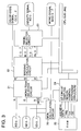
- Density data RD, GD and BD is further processed by color reproduction and EE circuits illustrated in Fig. 3.
- density data RD, GD and BD is inputted into an MON calculation circuit 20, and density data signal MOD for mono-tone color reproduction is calculated in this MON calculation circuit 20.
- the mono-tone selector circuit 21 into which density data MOD, RD, GD and BD is inputted three primary density data is selected and outputted according to the copy mode such as the copy mode of sepia and that of mono-tone.
- document images can be processed and outputted as a monochromatic image of a chromatic color such as sepia.
- a masking circuit 22 into which density data is inputted from the mono-tone selector circuit 21 color discrimination is carried out for each pixel, and a color code signal CC is outputted, which shows the attribution of each pixel, for example, each pixel belongs to which color of black Bk, yellow Y, magenta M, cyan C and white W.
- density information of R, G and B is converted into density data of yellow Y, magenta M, cyan C and black Bk, and then outputted. Density data of each color of Y, M, C and Bk is selected by the selector circuit 23. Then, color code signal CC and density data corresponding to color code signal CC are outputted.
- EE circuit 24 controls the sampling region of image data according to the information of a density histogram
- RAM 25 is a work memory used for making the density histogram.
- Color code signal CC, density signal ND showing its density data, and further density signal MOD for monotone reproduction are successively processed by a marker editing section shown in Fig. 4.
- a marker region processing circuit ⁇ inversion/half-tone processing circuit 32 detects an image processing region designated to be a closed loop with a marker pen in accordance with color code signal CC inputted through a delay circuit 31, and then a marker region signal is outputted.
- the marker region signal is stored in a judgment information memory circuit 105 described later.
- the processing of marker region inversion, half-tone, masking and trimming is carried out in accordance with a processing mode for each pixel corresponding to the marker designating region detected in the aforementioned prescanning process.
- a marker color conversion processing circuit 37 in the case where partial color conversion processing, which is one of marker editing processing operations, is designated, the color of an image in the marker region is converted into a color of the marker pen used for region designation, and the converted image is outputted through an output control circuit 38.
- RAM 39 various control data used for detection of a marker designating region, inversion and half-tone is stored.
- Density signal ND corresponding to color code signal CC is inputted into a color ⁇ mono-tone selector 34 through a delay circuit 33, and further color code signal CC is inputted through a delay circuit 31, and moreover mono-tone density signal MD is inputted through a region discrimination circuit 36 described later, and density data for color copying and density data for monochromatic copying are selectively outputted to a marker color conversion processing circuit 37.
- Mono-tone density signal MOD is inputted into the region discrimination circuit 36. Then, in accordance with mono-tone density signal MOD, it is discriminated whether or not a document image is a photographic image having gradation, and also it is discriminated whether or not the document image is a character and line image composed of characters and lines. The result of discrimination is outputted as a discrimination signal PM for each pixel.
- numeral 35 is a RAM that is a work memory provided in the region discrimination circuit 36.
- Density signal MD outputted through the output control circuit 38 after it has been edited with a marker is subjected to gradation conversion processing in the spatial filter processing section shown in Fig. 5.
- the spatial filter processing circuit includes two spatial filter processing circuits 41 and 42 that conduct gradation conversion in accordance with different factors A and B. Density data that has been subjected to gradation processing is selected by the data selector 43 in accordance with discrimination signal PM, and selected data is outputted as density data FD.
- the characteristics of gradation processing can be automatically changed to sharp or soft in accordance of an image to be processed, that is, when a document image is a photographic one, or a character and line one, the characteristics of gradation processing can be automatically changed.
- numeral 44 is a RAM used as a work memory for spatial filter processing calculation.
- Density data FD that has been subjected to gradation conversion processing in the spatial filter processing circuit shown in Fig. 5, is successively sent to a variable magnification processing section shown in Fig. 6.
- the variable magnification processing section includes an input side variable magnification processing circuit (A) 51, output side variable magnification processing circuit (B) 52, linear interpolation table (ROM) 53, and RAM 54 and 55 attached the variable magnification processing circuits (A) and (B).
- image processing is performed for magnifying or reducing a document image in accordance with a variable magnification ratio that has been selected and directed.
- density data adjoining in the direction of sensor element row (the primary scanning direction) is linearly interpolated and outputted as conversion data.
- input density data is thinned out in the direction of CCD sensor element row (the primary scanning direction) and outputted as conversion data.
- auxiliary scanning direction (the optical scanning direction, that is, the direction in which the halogen lamp 122 is moved) perpendicular to the primary scanning direction, an amount of data is increased or decreased for magnifying or reducing the document image when the reading speed (the scanning speed) is changed.
- variable magnification means of this example is composed of the variable magnification processing section shown in Fig. 6 when the reading speed is variably controlled.
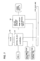
- Fig. 7 density data MRD that has been subjected to magnifying and reducing processing is processed by the spatial filter 61, and the color balance is adjusted by the color balance circuit (PWM circuit) 62. After that, the density data is converted into video signal VD.
- PWM circuit color balance circuit
- Video signal VD is supplied to color printer section B, and an image corresponding to video signal VD is formed on a recording paper so that a copy of the original document can be provided.
- numeral 63 is a RAM used for calculation of the spatial filter 61.
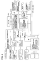
- Fig. 8 is a schematic illustration showing a processing document discrimination data unit that stores various image judgment information provided through prescanning.
- the color code signal, marker region signal and image discrimination signal PM which have been obtained through prescanning, are respectively decoded by the decoding circuits 101, 102 and 103, and written in the judgment information memory circuit 105 through the writing circuit 104. They are stored as editing data for each pixel together with processing mode information given by CPU 71 described later.
- Fig. 9 is a view showing CPU 71 controlling each processing circuit, and also showing a microcomputer section composed of the peripheral circuits.
- Each processing circuit shown in Figs. 2 and 8 and CPU 71 are connected through CPU bus line.
- CPU 71 sends a signal of recording paper designation and also sends a signal representing the result of document size detection, to the communication unit 73 of the printer main body (writing unit B and image forming section C) through the communication interface 72.
- a variable magnification region is designated.
- the operator encircles the region with another marker for the purpose of designating a magnification ratio of the region, thereby the region is encircled by a double loop.
- the illustration portion is encircled with a color marker so that a closed loop can be formed, and further the outside of the closed loop is encircled with another color marker for indicating an image region after magnification (a magnification size), thereby the illustration portion is encircled by the double loop.
- the color of the marker indicating the variable magnification region and that of the marker indicating the variable magnification size are different (for example, red and blue).
- variable magnification processing in which the variable magnification region and size are designated by a double closed loop of different color markers is referred to as double marker variable magnification, hereinafter.
- variable magnification condition detection means includes the marker region processing circuit 32, CPU 71, and judgment information memory circuit 105 to store the region signal.
- variable magnification processing region A and variable magnification size B variable magnification region
- a desired region can be magnified by a desired ratio without setting a numerical magnification ratio. Therefore, in the case where a specific region is required to be magnified to an arbitrary size, it is not necessary for the operator to calculate the magnification ratio, and an editor is not necessary, either. Consequently, partial variable magnification of an arbitrary magnification ratio can be performed through a simple operation.
- Colors to be used may be previously specified so as to designate colors corresponding to the variable magnification processing region and size (or the operator may select the colors to designate the variable magnification processing region and size). In this way, colors may designate the variable magnification region and size.
- the double marker variable magnification mode may be divided into an enlarging mode and a reducing mode. In the case of the enlarging mode, the inside closed loop may indicate the variable magnification processing region, and the outside closed loop may indicate the variable magnification size.
- image region A (variable magnification region) to be reduced is encircled with a color marker so that a closed loop can be formed as shown in Fig. 11, and at the same time, a closed loop of different color is formed inside the aforementioned loop so that image region B (variable magnification size) after reduction can be indicated.
- the variable magnification region and size can be respectively detected, and when a comparison is made between the two, the variable magnification ratio can be found. Accordingly, an image in the region designated with a color marker can be reduced to the size also designated with another color marker.
- variable magnification ratio is set in the following manner.
- variable magnification processing region A and variable magnification size B are detected by the marker region processing circuit 32, and marker region signals A and B are stored in the judgment information memory circuit 105. Then, in accordance with stored region signals A and B, CPU 71 calculates a variable magnification ratio by which magnification is performed from region A to region B.
- Fig. 12 in the case of enlarging processing
- Fig. 13 in the case of reducing processing
- the maximum width Am in the primary scanning direction and the maximum width As in the auxiliary scanning direction of variable magnification processing region A is found in accordance with stored marker region signal A
- the maximum width Bm in the primary scanning direction and the maximum width Bs in the auxiliary scanning direction of variable magnification size (region after variable magnification processing) B is found in accordance with stored marker region signal B.
- variable magnification ratio in the primary scanning direction is calculated by Bm/Am
- a variable magnification ratio in the auxiliary scanning direction is calculated by Bs/As
- the obtained results are temporarily stored in the memory.
- the stored variable magnification data in the auxiliary scanning direction is read through communication, and the read data is sent to the control system of the apparatus that controls the reading speed.
- the variable magnification data in the primary scanning direction is outputted to the variable magnification processing circuit shown in Fig. 6, so that an actual variable magnification processing operation is performed.
- image formation is carried out in the following manner when: the variable magnification size is indicated with a blue marker; partial color conversion is performed to convert to the marker color (the marker color of the outside closed loop) used for indication of the variable magnification size; and toner colors used for color recording are yellow Y, magenta M, cyan C and black Bk.
- a life size image is formed from black Bk toner.
- image reading is performed while the reading speed (scanning speed) is changed in accordance with the aforementioned variable magnification ratio Bs/As.
- marker editing processing is performed in the following manner: trimming processing is conducted so that only marker region A is recorded; color conversion processing is conducted so that marker region A is converted to blue; and in the variable magnification processing circuit, linear interpolation is conducted in the primary direction in accordance with variable magnification ratio Bm/Am.
- image data in the marker region that has been subjected to variable magnification and color conversion processing is supplied to color printer section B so that M and C images can be formed.
- the present color conversion is performed for converting to blue by superimposing M and C images. Therefore, it is not necessary to form a yellow Y toner image. Accordingly, the yellow Y toner image is not formed.
- marker editing processing is performed in the following manner: the marker region is masked with respect to an image signal that has been read by an ordinary reading speed for a life-size image; and the image signal of a life-size is supplied to color printer section B so that the life-size image of a region outside the marker region is formed.
- variable magnification processing region designated with a color marker is enlarged to a variable magnification size designated by another color marker; the color of the image is converted to blue and recorded; and the image outside the variable magnification processing region is recorded in a life-size under the condition that the color is black.
- image recording may be performed in the same manner.
- a Bk image of life-size and a Bk image of variable magnification are respectively formed and superimposed.
- variable magnification processing and partial color conversion which are indicated by a double marker, are combined so as to be carried out.
- the conventional editing processing such as half-tone, inversion and masking/trimming may be combined and carried out.
- half-tone and inversion mean half-tone and inversion processing performed on a region designated by a color marker.
- masking and trimming are combined, it is possible to enlarge an image inside the inner region to the outer marker region as shown in Fig. 17, and it is also possible to make a region inside the inner marker region to be white.
- the image data inside the inner marker region is not outputted.
- Half-tone, inversion and masking/trimming are combined when editing data is set in the process of prescanning as shown in Fig. 14.
- Combination of double marker variable magnification processing and other marker editing processing can be realized when editing data shown in Fig. 14 in which a marker region signal and various processing modes are combined is stored in the judgment information memory circuit 105.
- Editing data shown in Fig. 14 is information of 8 bits per one pixel, including: information showing whether half-tone, inversion, trimming, masking and color conversion are conducted or not; information showing conversion color in color conversion processing; and region signal information (A) and (B) showing variable magnification processing region A and variable magnification size B.
- region signal information (A) and (B) showing variable magnification processing region A and variable magnification size B.
- an operator encircles a region on a document to be magnified and an image region after variable magnification with markers of different colors so that a double loop can be formed (S1).
- the double marker document is set on a copier, and a double marker variable magnification mode is selected (S2).
- Regions A and B respectively showing the variable magnification processing region and variable magnification size (image region after variable magnification processing) designated by color markers are detected from the color image signal of the document provided through the aforementioned prescanning operation.
- Region signals A and B are stored in the judgment information memory circuit 105 (S4; variable magnification condition detection means).
- region A denotes the variable magnification processing region
- region B denotes the variable magnification size.
- regions A and B only denote the designation of a double closed loop.
- the maximum region width in the primary scanning direction in region A is calculated in accordance with region signal A stored in the judgment information memory circuit 105 (S5). Also, the maximum region width in the auxiliary scanning direction is calculated (S6). The results of calculation are stored as control data of CPU 71.
- the maximum region width in the primary scanning direction in region A is calculated in accordance with region signal A stored in the judgment information memory circuit 105 (S5). Also, the maximum region width in the auxiliary scanning direction is calculated (S6). The results of calculation are stored as control data of CPU 71.
- the maximum region width in the primary scanning direction in region B is calculated in accordance with region signal B stored in the judgment information memory circuit 105 (S5). Also, the maximum region width in the auxiliary scanning direction is calculated (S8). The results of calculation are stored as control data of CPU 71.
- the variable magnification ratio in the primary scanning direction is calculated (S9).
- the variable magnification ratio is calculated by (the maximum width of the primary scanning direction in region B)/(the maximum width of the primary scanning direction in region A).
- the variable magnification ratio is calculated by (the maximum width of the primary scanning direction in region A)/(the maximum width of the primary scanning direction in region B).
- variable magnification ratio in the auxiliary scanning direction is calculated (S10).
- the calculated variable magnification ratios of the primary and auxiliary scanning directions are transmitted to the control system of the apparatus through a communication means, and the reading speed is controlled correspondingly to the calculated variable magnification ratio.
- Each variable magnification ratio is set before prescanning and the image processing preparation is completed (S11).
- the main scanning operation is carried out.
- the following conditions are set in the case of a monochromatic document: enlarging processing is carried out when the region is designated with a double marker (that is, the inner region is enlarged to the outer region); and the variable magnification processing region is subjected to color-conversion so that the color can be converted into a marker color used for the outside closed loop of the double marker (S12).
- reading is performed in accordance with the variable magnification ratio of the auxiliary scanning direction that has been previously set in prescanning, and only a variable magnification processing region designated as the inner region of the double marker is extracted from the region that has been read. Then, the extracted region is subjected to color-conversion in accordance with the decision by the outside marker color. Moreover, an enlargement processing operation of the primary scanning direction is carried out by means of interpolating calculation in accordance with the variable magnification ratio of the primary scanning direction that has been previously set in prescanning. Then, the formation Y-image is carried out in accordance with the signal obtained by this processing (S13).
- Life-size and monochromatic recording is performed in a region except for the region designated by the color marker. Therefore, in the formation of a Bk image, an image signal outside of the marker designated region is extracted from the image signal obtained through the reading speed corresponding to the life-size image formation, and the image is outputted to the printer section without conducting variable magnification processing in the variable magnification processing circuit. In this way, the image Bk outside of the marker designated region can be formed (S16).
- the document is monochromatic, however, the present invention is not limited to a monochromatic document.
- the present invention may be applied to a color document.
- a discrimination can not be made between the region designated by a color marker and the document image.
- the following measures may be taken: as the present applicant has proposed before, a fluorescent marker having high reflectivity is used for region designation so that a discrimination can be made between the image portion and the marker designation region (disclosed in Japanese Patent Publication Open to Public Inspection No. 145630/1992).
- variable magnification region variable magnification processing region and variable magnification size
- the variable magnification region of an original color document is designated on a monochromatic portion or a white portion on the original color document with a color marker
- the monochromatic portion or the white portion is read so that the processing mode is set
- the original color document is read (disclosed in Japanese Patent Publication Open to Public Inspection No. 134980/1992).
- the image signal that has been subjected to variable magnification processing is outputted to a color printer section.
- the present invention is not limited to the specific example, and the image signal may be outputted to a display device such as a CRT.
- variable magnification ratio can be easily set in the variable magnification processing.
Landscapes
- Engineering & Computer Science (AREA)
- Multimedia (AREA)
- Signal Processing (AREA)
- Editing Of Facsimile Originals (AREA)
- Processing Or Creating Images (AREA)
- Image Processing (AREA)
- Character Discrimination (AREA)
Applications Claiming Priority (2)
| Application Number | Priority Date | Filing Date | Title |
|---|---|---|---|
| JP4198632A JPH0646249A (ja) | 1992-07-24 | 1992-07-24 | 画像処理装置 |
| JP198632/92 | 1992-07-24 |
Publications (2)
| Publication Number | Publication Date |
|---|---|
| EP0580424A2 true EP0580424A2 (de) | 1994-01-26 |
| EP0580424A3 EP0580424A3 (en) | 1994-06-01 |
Family
ID=16394434
Family Applications (1)
| Application Number | Title | Priority Date | Filing Date |
|---|---|---|---|
| EP19930305746 Withdrawn EP0580424A3 (en) | 1992-07-24 | 1993-07-21 | Image processing apparatus having variable magnification means |
Country Status (3)
| Country | Link |
|---|---|
| US (1) | US5363211A (de) |
| EP (1) | EP0580424A3 (de) |
| JP (1) | JPH0646249A (de) |
Families Citing this family (15)
| Publication number | Priority date | Publication date | Assignee | Title |
|---|---|---|---|---|
| DE4318526C2 (de) * | 1992-06-10 | 1999-11-25 | Canon Kk | Bildeingabevorrichtung |
| JPH06133151A (ja) * | 1992-10-14 | 1994-05-13 | Konica Corp | 画像処理装置 |
| US5424853A (en) * | 1993-04-19 | 1995-06-13 | Sharp Kabushiki Kaisha | Image processing apparatus |
| JP2813728B2 (ja) * | 1993-11-01 | 1998-10-22 | インターナショナル・ビジネス・マシーンズ・コーポレイション | ズーム/パン機能付パーソナル通信機 |
| US5455898A (en) * | 1993-11-24 | 1995-10-03 | Xerox Corporation | Analyzing an image showing a graphical representation of a layout |
| US5659639A (en) * | 1993-11-24 | 1997-08-19 | Xerox Corporation | Analyzing an image showing editing marks to obtain category of editing operation |
| JP3478877B2 (ja) * | 1994-09-30 | 2003-12-15 | ミノルタ株式会社 | 画像形成装置 |
| US5631746A (en) * | 1994-11-15 | 1997-05-20 | Lexmark International, Inc. | High resolution simulation printing by printing adjoining pels |
| JP3166555B2 (ja) * | 1995-04-13 | 2001-05-14 | 富士ゼロックス株式会社 | 文書処理装置 |
| US6026435A (en) * | 1996-07-12 | 2000-02-15 | Sanyo Electric Co., Ltd. | Internet information displaying apparatus and internet information displaying method |
| US6738531B1 (en) * | 1999-05-10 | 2004-05-18 | Fuji Photo Film Co., Ltd. | Image processing method and apparatus |
| US7120299B2 (en) * | 2001-12-28 | 2006-10-10 | Intel Corporation | Recognizing commands written onto a medium |
| US7454707B2 (en) * | 2002-09-30 | 2008-11-18 | Canon Kabushiki Kaisha | Image editing method, image editing apparatus, program for implementing image editing method, and recording medium recording program |
| US20150100869A1 (en) * | 2008-02-25 | 2015-04-09 | Tixtrack, Inc. | Sports and concert event ticket pricing and visualization system |
| JP4875723B2 (ja) * | 2009-04-24 | 2012-02-15 | シャープ株式会社 | 画像形成装置 |
Family Cites Families (6)
| Publication number | Priority date | Publication date | Assignee | Title |
|---|---|---|---|---|
| JPS62157070A (ja) * | 1985-12-28 | 1987-07-13 | Konishiroku Photo Ind Co Ltd | 現像方法 |
| JPS63213887A (ja) * | 1987-03-03 | 1988-09-06 | ミノルタ株式会社 | 編集制御表示方式 |
| JPH027369A (ja) * | 1988-06-27 | 1990-01-11 | Japan Storage Battery Co Ltd | カドミウム負極板およびその負極板を用いたアルカリ二次電池 |
| JPH0262671A (ja) * | 1988-08-30 | 1990-03-02 | Toshiba Corp | カラー編集処理装置 |
| DE69021107T2 (de) * | 1989-03-22 | 1995-12-14 | Konishiroku Photo Ind | Bildverarbeitungsvorrichtung, fähig zur Detektion markierter Gebiete. |
| JPH0775393B2 (ja) * | 1990-08-23 | 1995-08-09 | 富士ゼロックス株式会社 | 編集機能付き複写機 |
-
1992
- 1992-07-24 JP JP4198632A patent/JPH0646249A/ja active Pending
-
1993
- 1993-07-20 US US08/093,868 patent/US5363211A/en not_active Expired - Fee Related
- 1993-07-21 EP EP19930305746 patent/EP0580424A3/en not_active Withdrawn
Also Published As
| Publication number | Publication date |
|---|---|
| JPH0646249A (ja) | 1994-02-18 |
| US5363211A (en) | 1994-11-08 |
| EP0580424A3 (en) | 1994-06-01 |
Similar Documents
| Publication | Publication Date | Title |
|---|---|---|
| US5363211A (en) | Image processing apparatus having means for magnifying a portion of a document selected through color marking | |
| JPH01228268A (ja) | 色情報補正装置 | |
| JPH02288670A (ja) | カラー画像処理装置 | |
| US5177603A (en) | Image copying apparatus having means for deleting color portions of an original image | |
| JPH10341341A (ja) | 画像処理装置 | |
| JPH03230681A (ja) | カラー画像処理装置 | |
| JPH08251402A (ja) | 画像処理装置 | |
| US5321531A (en) | Image processing apparatus capable of document discrimination | |
| US5666207A (en) | Image processing apparatus | |
| JPH06121146A (ja) | 画像処理装置 | |
| JP2788479B2 (ja) | カラー画像処理装置 | |
| JPH06133151A (ja) | 画像処理装置 | |
| JP2951964B2 (ja) | 画像形成装置 | |
| JPH05344314A (ja) | 画像処理装置 | |
| JP3079630B2 (ja) | 画像処理装置 | |
| JP2837418B2 (ja) | カラー画像処理装置 | |
| JP3220812B2 (ja) | 画像処理装置 | |
| JP3241092B2 (ja) | デジタル複写機 | |
| JP3128872B2 (ja) | 画像編集装置 | |
| JP3245883B2 (ja) | 画像形成装置 | |
| JP3020562B2 (ja) | 画像再生装置 | |
| JP3185926B2 (ja) | 画像処理装置および画像処理方法 | |
| JPH06133150A (ja) | 画像処理装置 | |
| JP2637522B2 (ja) | カラー画像処理装置 | |
| JPH02280573A (ja) | カラー画像処理装置 |
Legal Events
| Date | Code | Title | Description |
|---|---|---|---|
| PUAI | Public reference made under article 153(3) epc to a published international application that has entered the european phase |
Free format text: ORIGINAL CODE: 0009012 |
|
| AK | Designated contracting states |
Kind code of ref document: A2 Designated state(s): DE FR GB IT NL |
|
| PUAL | Search report despatched |
Free format text: ORIGINAL CODE: 0009013 |
|
| AK | Designated contracting states |
Kind code of ref document: A3 Designated state(s): DE FR GB IT NL |
|
| 17P | Request for examination filed |
Effective date: 19941104 |
|
| 17Q | First examination report despatched |
Effective date: 19961024 |
|
| STAA | Information on the status of an ep patent application or granted ep patent |
Free format text: STATUS: THE APPLICATION IS DEEMED TO BE WITHDRAWN |
|
| 18D | Application deemed to be withdrawn |
Effective date: 19971126 |