EP0579898B1 - Dispositif de mesure et de découpage de bois rond - Google Patents
Dispositif de mesure et de découpage de bois rond Download PDFInfo
- Publication number
- EP0579898B1 EP0579898B1 EP93102172A EP93102172A EP0579898B1 EP 0579898 B1 EP0579898 B1 EP 0579898B1 EP 93102172 A EP93102172 A EP 93102172A EP 93102172 A EP93102172 A EP 93102172A EP 0579898 B1 EP0579898 B1 EP 0579898B1
- Authority
- EP
- European Patent Office
- Prior art keywords
- measuring
- cross
- cutting
- trunk
- timber
- Prior art date
- Legal status (The legal status is an assumption and is not a legal conclusion. Google has not performed a legal analysis and makes no representation as to the accuracy of the status listed.)
- Expired - Lifetime
Links
- 238000005520 cutting process Methods 0.000 title claims abstract description 42
- 238000005259 measurement Methods 0.000 claims description 9
- 238000000034 method Methods 0.000 claims description 3
- 238000004891 communication Methods 0.000 claims 1
- 238000007493 shaping process Methods 0.000 claims 1
- 238000010276 construction Methods 0.000 description 5
- 239000000463 material Substances 0.000 description 4
- 239000002023 wood Substances 0.000 description 4
- 238000005457 optimization Methods 0.000 description 3
- 230000004888 barrier function Effects 0.000 description 2
- 238000009966 trimming Methods 0.000 description 2
- 229910000831 Steel Inorganic materials 0.000 description 1
- 230000005540 biological transmission Effects 0.000 description 1
- 238000005265 energy consumption Methods 0.000 description 1
- 238000000605 extraction Methods 0.000 description 1
- 238000003825 pressing Methods 0.000 description 1
- 238000004904 shortening Methods 0.000 description 1
- 239000010959 steel Substances 0.000 description 1
- 230000001960 triggered effect Effects 0.000 description 1
Images


Classifications
-
- B—PERFORMING OPERATIONS; TRANSPORTING
- B23—MACHINE TOOLS; METAL-WORKING NOT OTHERWISE PROVIDED FOR
- B23D—PLANING; SLOTTING; SHEARING; BROACHING; SAWING; FILING; SCRAPING; LIKE OPERATIONS FOR WORKING METAL BY REMOVING MATERIAL, NOT OTHERWISE PROVIDED FOR
- B23D47/00—Sawing machines or sawing devices working with circular saw blades, characterised only by constructional features of particular parts
- B23D47/04—Sawing machines or sawing devices working with circular saw blades, characterised only by constructional features of particular parts of devices for feeding, positioning, clamping, or rotating work
-
- B—PERFORMING OPERATIONS; TRANSPORTING
- B23—MACHINE TOOLS; METAL-WORKING NOT OTHERWISE PROVIDED FOR
- B23D—PLANING; SLOTTING; SHEARING; BROACHING; SAWING; FILING; SCRAPING; LIKE OPERATIONS FOR WORKING METAL BY REMOVING MATERIAL, NOT OTHERWISE PROVIDED FOR
- B23D59/00—Accessories specially designed for sawing machines or sawing devices
- B23D59/001—Measuring or control devices, e.g. for automatic control of work feed pressure on band saw blade
-
- B—PERFORMING OPERATIONS; TRANSPORTING
- B23—MACHINE TOOLS; METAL-WORKING NOT OTHERWISE PROVIDED FOR
- B23D—PLANING; SLOTTING; SHEARING; BROACHING; SAWING; FILING; SCRAPING; LIKE OPERATIONS FOR WORKING METAL BY REMOVING MATERIAL, NOT OTHERWISE PROVIDED FOR
- B23D59/00—Accessories specially designed for sawing machines or sawing devices
- B23D59/008—Accessories specially designed for sawing machines or sawing devices comprising computers
-
- B—PERFORMING OPERATIONS; TRANSPORTING
- B27—WORKING OR PRESERVING WOOD OR SIMILAR MATERIAL; NAILING OR STAPLING MACHINES IN GENERAL
- B27B—SAWS FOR WOOD OR SIMILAR MATERIAL; COMPONENTS OR ACCESSORIES THEREFOR
- B27B1/00—Methods for subdividing trunks or logs essentially involving sawing
- B27B1/002—Methods for subdividing trunks or logs essentially involving sawing by cross-cutting
-
- B—PERFORMING OPERATIONS; TRANSPORTING
- B27—WORKING OR PRESERVING WOOD OR SIMILAR MATERIAL; NAILING OR STAPLING MACHINES IN GENERAL
- B27B—SAWS FOR WOOD OR SIMILAR MATERIAL; COMPONENTS OR ACCESSORIES THEREFOR
- B27B17/00—Chain saws; Equipment therefor
- B27B17/0041—Saw benches or saw bucks
- B27B17/0058—Saw benches or saw bucks with the saw being pivotally mounted
Definitions
- the invention relates to a log measuring and cutting device according to the preamble of claim 1 for use in sawmills; see US-A 4,468,993.
- the long logs are removed from the log yard with a track-bound crane truck, placed on the cut-to-length pile and immovably fixed by mechanical or hydraulic clamping jaws.
- a measuring device and a cross-cut saw are attached to the crane truck to record the dimensions of the log and to cut it to length.
- the crane truck travels to one end of the trunk, uses the chop saw to make a smooth cut to precisely determine the zero point of the length measurement and travels the entire trunk, with diameter measurements being carried out at certain grid intervals.
- the measurement results are entered into a computer and compared with the saved timber dimensions of the existing orders.
- the computer then makes a suggestion for the optimal cutting of the trunk.
- the crane truck now moves to the specified positions and makes the cuts with the cross-cut saw.
- the invention has for its object to develop a log measuring and cutting device that avoids the aforementioned disadvantages, accelerates the measuring process and enables a significantly higher material throughput.
- a particular advantage of the invention is that the measuring and cutting car is provided separately from the timber transport vehicle (crane truck) and has a significantly reduced mass compared to it and can therefore be moved much faster, thereby shortening the measuring and cutting times enormously and the material throughput is significantly increased overall.
- the timber transport vehicle is no longer tied to the measuring and cutting process and is free during this time for its actual tasks, namely the timber transport. This also helps to increase the material throughput at.
- the "empty trips" of the heavy timber transport and sorting trolley during the measurement and cutting to length also result in considerable energy savings.
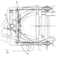
- the long logs 1 are deposited by the crane of the timber transport and sorting carriage traveling on the tracks 2 on the cut-to-length pile 3, which is firmly connected to the foundation 8.
- a special position control device ensures that the trunk is placed in such a way that it can be easily run over by the measuring and cutting car 4. If the trunk is outside the permissible range, a warning signal is triggered and the carriage stops automatically.
- the entire trunk is run over by the measuring and cutting car 4 in its entire length, which is remotely controlled from the control cabin of the timber transport vehicle.
- a measuring curtain 13 is provided on the frame 9 of the measuring and cutting carriage 4, which has a light of, for example, 1 m x 1 m, so that logs up to 1 m in diameter and larger can be measured.
- the length is measured by measuring the distance covered by the wagon and starts at any end of the trunk.
- the zero line is formed by specifying a smooth cut at a certain distance from the end of the trunk.
- the trunk diameters are evaluated in suitable grids, stored in a computer installed in shelter 6 and displayed on a screen (terminal) in the control cabin of the timber transport and sorting trolley.
- the computer After the entire trunk has been traversed, the computer, by comparing it with the existing orders stored in it, outputs optimal form suggestions, which are displayed on the screen in the control cabin of the timber transport vehicle.
- the operator seated in the wood transport vehicle confirms the execution of the schedule suggestions given by the computer by pressing a button.
- the computer which, as mentioned, manages the order list, then saves the sections intended for cutting to length.
- the measuring and cutting car 4 is automatically stopped at the end of the trunk.
- the trimming of the trunk with the chop saw 12 takes place in the reverse sequence to the measuring direction, ie the trimming begins immediately from the end of the trunk reached during the measurement.
- the chop saw 12, like the measuring curtain 13, is firmly connected to the frame of the measuring and cutting car and is controlled automatically or by manual control from the control station.
- the section length is again determined by measuring the distance traveled by the measuring and cutting carriage and the cross-cut saw is thus moved into the corresponding desired positions.
- the trunk is fixed by moving the clamping jaws 11 together.
- a moving floor or scraper conveyor can be installed between the tracks of the measuring and cutting car 4.
- the sawdust created during the cutting process can be sucked off directly on the sword by means of an appropriate extraction system.
- an additional lifting device on the clamping jaws which slightly raises the trunk when cutting to prevent the chainsaw from jamming and cutting into the support wood or other parts.
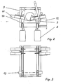
- this lifting device is formed according to FIG. 5 from a thrust piston gear 14 arranged on a crossbar, which engages a lifting arm 16 connected to the joint 15 of a pair of clamping jaws.
- a thrust piston gear 14 is provided for each pair of jaws.
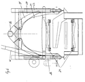
- the clamping device has two pairs of clamping jaws 17 and 18, between which the chop saw 12 is arranged. The two jaws of each pair of jaws 17, 18 are connected to one another at their upper end via a joint 15, below the joint the ends of thrust piston drives 19, 20 which are also designed as piston-cylinder units and which engage the jaws in the clamping position.
- the portal 9 is expediently formed as a square tube construction, with in the area of the uprights and crossbeams At least at the front and rear ends of the portal, side walls 29 are provided, which have a recess 30 in the form of an inverted U for the trunk passage.
- the portal 9 carries the measuring curtain, the chop saw and the clamping device and has a drive, the undercarriage being formed by two or four wheels on the longitudinal beams.
- Two or four slip-on geared motors are preferably provided on the wheels for control via frequency converters.
- a scraper can be arranged in front of and after each wheel, which removes dirt from the track.
- trunk clamping arms guided in the square tube with plastic insert can be provided on the left and right of the saw blade, which can be actuated individually via cylinders.
- the cylinders can be coupled via flow dividers that compensate for irregularities.
- the measuring curtain is housed on the portal and, in one embodiment, has two vertical, opposite light strips for determining the vertical trunk diameter.
- horizontally or diagonally aligned light bars arranged one above the other can be provided, so that the trunk is then guided through four light bars, whereby the horizontal diameter of the trunk can also be measured.
- the optimization system with the computer can be arranged on the measuring and cutting trolley, the data being transmitted by radio to the operating system, which is preferably arranged on the wood transport and sorting trolley.
- a radio transmission a data light barrier is also possible, but then the light signal transmitter on the carriage must be aligned in a straight line with the receiver, from which the data are then transmitted via radio to the wooden transport carriage.
- the optimization system with the computer can also be arranged outside the car, in which case a trailing cable or a radio link or data light barriers is present between the measuring curtain and the optimization system.
- a separate measuring wheel is preferably provided, via which the measurement is carried out with a rotary pulse encoder.
- the pulse generator can also act on one of the non-driven wheels of the car. If one can speak of wheels here, it is clear that these can be rail-independent wheels, or also wheels that interact with rails.
- the trunk can be stationary on the wooden shelf made of a section steel construction according to FIGS. 4 and 5, over which the measuring and cutting car travels.
- a drive 31 is preferably used for the removal of the separated trunk sections.
Landscapes
- Engineering & Computer Science (AREA)
- Mechanical Engineering (AREA)
- Life Sciences & Earth Sciences (AREA)
- Wood Science & Technology (AREA)
- Forests & Forestry (AREA)
- Length Measuring Devices By Optical Means (AREA)
- Debarking, Splitting, And Disintegration Of Timber (AREA)
- Sorting Of Articles (AREA)
- Continuous Casting (AREA)
- Warehouses Or Storage Devices (AREA)
Claims (10)
- Dispositif de mesure et de découpage de bois rond pour lequel des troncs de long bois sont déposés par une grue mobile sur un dispositif fixe de découpage (3) et leur longueur et diamètre mesurés, les valeurs mesurées étant comparées avec une valeur théorique mémorisée dans un ordinateur et spécifique à la commande et des sections de découpage optimisées par cette comparaison étant déterminées, caractérisé en ce qu'un chariot de mesure et de découpage (4) lié au dispositif de découpage (3), déplaçable sur l'ensemble de l'étendue longitudinale, télécommandé et sur lequel sont montés tous les agrégats de mesure et de découpage est prévu.
- Dispositif selon la revendication 2, caractérisé en ce que les mesures du diamètre s'effectuent dans des sections longitudinales données sur la longueur du tronc et les résultats des mesures sont transmis sur un ordinateur qui est disposé sur ou en dehors du chariot de mesure et de découpage (4) et établit, après la détermination des mesures de chaque tronc en comparaison avec les valeurs théoriques spécifiques à la commande, des propositions de démoulage optimisées qui sont représentées sur un écran, de façon privilégiée dans la cabine de commande d'un véhicule de transport de bois, cabine à partir de laquelle le chariot de mesure et de découpage est télécommandé.
- Dispositif selon les revendications 1 ou 2, caractérisé en ce que la transmission des données entre le chariot de mesure et de découpage, l'ordinateur et/ou le véhicule de transport et de triage de bois s'effectue sans fil par radio, par un barrage photoélectrique de données ou par un câble.
- Dispositif selon l'une des revendications précédentes, caractérisé en ce qu'une scie oscillatoire (12) pour le découpage du tronc, un rideau de mesure (13) pour déterminer le diamètre du tronc et un dispositif de serrage (11) pour maintenir le tronc pendant la coupe sont disposés sur le châssis du chariot de mesure et de découpage (4) et commandés automatiquement ou manuellement à partir du véhicule de transport de bois, par exemple d'un excavateur.
- Dispositif selon la revendication 4, caractérisé en ce qu'un dispositif de levage supplémentaire (14, 16) pour soulever le tronc pendant la coupe mord sur le dispositif de serrage (11).
- Dispositif selon l'une des revendications précédentes, caractérisé en ce que le chariot de mesure et de découpage (4) est réalisé à la manière d'un portique (9) et est constitué de façon privilégiée de deux poutres longitudinales (21, 22) inférieures supportant les roues, avec des montants verticaux avant et arrière (23 à 26) qui sont assemblés l'un à l'autre pour former le portique (9) par des poutres longitudinales transversale et supérieure (27, 28), le rideau de mesure, la scie oscillatoire ainsi que le dispositif de serrage étant disposés à l'intérieur du portique.
- Dispositif selon l'une des revendications précédentes, caractérisé en ce que le dispositif de serrage présente une paire de mâchoires de serrage (17, 18) ressemblant à des pinces et disposée devant et derrière la scie oscillatoire (12), les mâchoires de serrage de chaque paire étant reliées à une articulation (15) à leur extrémité supérieure et chaque mâchoire pouvant être déplacée par l'intermédiaire d'un engrenage à piston de poussée (19, 20) se présentant de façon privilégiée sous la forme d'un vérin à piston, logé dans le portique (9) et qui mord sur la mâchoire en dessous de l'articulation.
- Dispositif selon la revendication 7, caractérisé en ce que les paires de mâchoires de serrage (17, 18) peuvent être soulevées de façon indépendante ou ensemble par un dispositif de levage (14, 16) pour le processus de coupe, dispositif de levage qui relève ou abaisse la paire de mâchoires de serrage et est constitué de façon privilégiée d'une commande linéaire (14) se présentant sous la forme d'un vérin à piston et qui saisit un bras de levage relié à l'articulation (15).
- Dispositif selon la revendication 8, caractérisé en ce que la commande linaire (14) est disposée sur une poutre transversale reliant les poutres longitudinales transversales supérieures (27, 28) ou sur les poutres longitudinales supérieures.
- Dispositif selon l'une des revendications précédentes, caractérisé en ce que le rideau de mesure est constitué de deux barres lumineuses verticales ou de deux barres lumineuses verticales et de deux horizontales ou diagonales entre lesquelles se trouve le tronc lors du processus de mesure.
Applications Claiming Priority (2)
| Application Number | Priority Date | Filing Date | Title |
|---|---|---|---|
| DE4223856 | 1992-07-20 | ||
| DE4223856 | 1992-07-20 |
Publications (2)
| Publication Number | Publication Date |
|---|---|
| EP0579898A1 EP0579898A1 (fr) | 1994-01-26 |
| EP0579898B1 true EP0579898B1 (fr) | 1997-07-30 |
Family
ID=6463651
Family Applications (1)
| Application Number | Title | Priority Date | Filing Date |
|---|---|---|---|
| EP93102172A Expired - Lifetime EP0579898B1 (fr) | 1992-07-20 | 1993-02-11 | Dispositif de mesure et de découpage de bois rond |
Country Status (3)
| Country | Link |
|---|---|
| EP (1) | EP0579898B1 (fr) |
| AT (1) | ATE156051T1 (fr) |
| DE (1) | DE59306995D1 (fr) |
Families Citing this family (1)
| Publication number | Priority date | Publication date | Assignee | Title |
|---|---|---|---|---|
| FR2726781A1 (fr) * | 1994-11-15 | 1996-05-15 | Logsys | Installation pour le tronconnage et/ou l'usinage de grumes |
Family Cites Families (6)
| Publication number | Priority date | Publication date | Assignee | Title |
|---|---|---|---|---|
| US3771395A (en) * | 1968-06-28 | 1973-11-13 | C Heimerl | Log slasher |
| SE424160B (sv) * | 1981-02-16 | 1982-07-05 | Hammars Mekaniska Verkstad Ab | Forfarande och anordning for aptering och uppkapning av stammar efter dimensionsmetning |
| AT375863B (de) * | 1982-03-26 | 1984-09-25 | King Murphy Lavalin Inc | Vorrichtung zum saegen von staemmen in stuecke |
| US4468993A (en) * | 1982-06-11 | 1984-09-04 | International Paper Company | Small log bucking system |
| SE463086B (sv) * | 1986-06-30 | 1990-10-08 | Interlog Ab | Stockapteringsanordning |
| US4901611A (en) * | 1989-03-30 | 1990-02-20 | Bentley Richard J | Apparatus and method for cutting mults from billets |
-
1993
- 1993-02-11 EP EP93102172A patent/EP0579898B1/fr not_active Expired - Lifetime
- 1993-02-11 DE DE59306995T patent/DE59306995D1/de not_active Expired - Fee Related
- 1993-02-11 AT AT93102172T patent/ATE156051T1/de not_active IP Right Cessation
Also Published As
| Publication number | Publication date |
|---|---|
| EP0579898A1 (fr) | 1994-01-26 |
| DE59306995D1 (de) | 1997-09-04 |
| ATE156051T1 (de) | 1997-08-15 |
Similar Documents
| Publication | Publication Date | Title |
|---|---|---|
| DE2817634C2 (fr) | ||
| DE102007010101A1 (de) | Verfahren zur Herstellung eines Versorgungsleitungskanals sowie Zug bestehend aus Fahrzeugen zur Durchführung des Verfahrens | |
| EP0727385B1 (fr) | Grue mobile sur rails | |
| DD256890A5 (de) | Anlage zum aufnehmen oder verlegen, sowie transportieren von gleisjochen | |
| DE2713634A1 (de) | Fahrbare maschinenanordnung zum transport von schuettgut | |
| DE3430002C2 (fr) | ||
| DD256158A5 (de) | Fahrbare anlage zum aufnehmen oder verlegen sowie transportieren von gleisjochen | |
| DE2614921C3 (de) | Vor der Ausstoßöffnung einer Müllpresse angeordnete Wechselvorrichtung für Container | |
| DE3409854C2 (fr) | ||
| EP0579898B1 (fr) | Dispositif de mesure et de découpage de bois rond | |
| DE2140901C3 (de) | Rangierhilfsvorrichtung | |
| DE3213421C2 (fr) | ||
| DE2228196A1 (de) | Verfahren und anordnung zur erneuerung von eisenbahnschienenabschnitten | |
| DE1918599C3 (de) | Vorrichtung zur Aufbereitung von Rund holz | |
| DE2315648C2 (de) | Hochgarage | |
| DE2941611C2 (fr) | ||
| DE2719727A1 (de) | Gabelstapelgeraet | |
| DE19625438A1 (de) | Fahrbare Aufbereitungsmaschine, insbesondere Siebmaschine, für Bettungsschotter im Bahnwesen | |
| DE2648251A1 (de) | Lastkraftfahrzeug mit einer hebeeinrichtung | |
| DE4330406A1 (de) | Meßanlage für längliche Gegenstände, insbesondere Holzstämme | |
| DD239817A5 (de) | Gleisstopfmaschine mit strecken-stopfaggregat | |
| DE2936160A1 (de) | Anlage zum verladen schwerer lasten auf lastfahrzeuge o.dgl. mittels belademaschine | |
| DE2529975A1 (de) | Fahrbare einrichtung zum aufnehmen oder verlegen von gleisschwellen | |
| DE9210587U1 (de) | Anlage zum Ein- und Auslagern bzw. zur Speicherung von unterschiedlichen Gütern bzw. Lasten in einem eine Vielzahl von Stellplätzen aufweisenden Speichersilo | |
| DE2350988A1 (de) | Schienengebundener rundholztransportwagen mit bordeigenem hebezeug |
Legal Events
| Date | Code | Title | Description |
|---|---|---|---|
| PUAI | Public reference made under article 153(3) epc to a published international application that has entered the european phase |
Free format text: ORIGINAL CODE: 0009012 |
|
| AK | Designated contracting states |
Kind code of ref document: A1 Designated state(s): AT CH DE FR LI |
|
| 17P | Request for examination filed |
Effective date: 19940127 |
|
| 17Q | First examination report despatched |
Effective date: 19960118 |
|
| GRAG | Despatch of communication of intention to grant |
Free format text: ORIGINAL CODE: EPIDOS AGRA |
|
| GRAH | Despatch of communication of intention to grant a patent |
Free format text: ORIGINAL CODE: EPIDOS IGRA |
|
| GRAH | Despatch of communication of intention to grant a patent |
Free format text: ORIGINAL CODE: EPIDOS IGRA |
|
| GRAA | (expected) grant |
Free format text: ORIGINAL CODE: 0009210 |
|
| AK | Designated contracting states |
Kind code of ref document: B1 Designated state(s): AT CH DE FR LI |
|
| REF | Corresponds to: |
Ref document number: 156051 Country of ref document: AT Date of ref document: 19970815 Kind code of ref document: T |
|
| RIN1 | Information on inventor provided before grant (corrected) |
Inventor name: JECKLE, FRANZ Inventor name: BERTELE, GEBHARD |
|
| REG | Reference to a national code |
Ref country code: CH Ref legal event code: NV Representative=s name: AMMANN PATENTANWAELTE AG BERN Ref country code: CH Ref legal event code: EP |
|
| REF | Corresponds to: |
Ref document number: 59306995 Country of ref document: DE Date of ref document: 19970904 |
|
| ET | Fr: translation filed | ||
| PGFP | Annual fee paid to national office [announced via postgrant information from national office to epo] |
Ref country code: FR Payment date: 19980216 Year of fee payment: 6 |
|
| PGFP | Annual fee paid to national office [announced via postgrant information from national office to epo] |
Ref country code: AT Payment date: 19980219 Year of fee payment: 6 |
|
| PGFP | Annual fee paid to national office [announced via postgrant information from national office to epo] |
Ref country code: CH Payment date: 19980220 Year of fee payment: 6 |
|
| PGFP | Annual fee paid to national office [announced via postgrant information from national office to epo] |
Ref country code: DE Payment date: 19980420 Year of fee payment: 6 |
|
| PLBE | No opposition filed within time limit |
Free format text: ORIGINAL CODE: 0009261 |
|
| STAA | Information on the status of an ep patent application or granted ep patent |
Free format text: STATUS: NO OPPOSITION FILED WITHIN TIME LIMIT |
|
| 26N | No opposition filed | ||
| PG25 | Lapsed in a contracting state [announced via postgrant information from national office to epo] |
Ref country code: AT Free format text: LAPSE BECAUSE OF NON-PAYMENT OF DUE FEES Effective date: 19990211 |
|
| PG25 | Lapsed in a contracting state [announced via postgrant information from national office to epo] |
Ref country code: LI Free format text: LAPSE BECAUSE OF NON-PAYMENT OF DUE FEES Effective date: 19990228 Ref country code: CH Free format text: LAPSE BECAUSE OF NON-PAYMENT OF DUE FEES Effective date: 19990228 |
|
| REG | Reference to a national code |
Ref country code: CH Ref legal event code: PL |
|
| PG25 | Lapsed in a contracting state [announced via postgrant information from national office to epo] |
Ref country code: FR Free format text: LAPSE BECAUSE OF NON-PAYMENT OF DUE FEES Effective date: 19991029 |
|
| PG25 | Lapsed in a contracting state [announced via postgrant information from national office to epo] |
Ref country code: DE Free format text: LAPSE BECAUSE OF NON-PAYMENT OF DUE FEES Effective date: 19991201 |
|
| REG | Reference to a national code |
Ref country code: FR Ref legal event code: ST |