EP0579898B1 - Measuring and cross cutting system for round timber - Google Patents
Measuring and cross cutting system for round timber Download PDFInfo
- Publication number
- EP0579898B1 EP0579898B1 EP93102172A EP93102172A EP0579898B1 EP 0579898 B1 EP0579898 B1 EP 0579898B1 EP 93102172 A EP93102172 A EP 93102172A EP 93102172 A EP93102172 A EP 93102172A EP 0579898 B1 EP0579898 B1 EP 0579898B1
- Authority
- EP
- European Patent Office
- Prior art keywords
- measuring
- cross
- cutting
- trunk
- timber
- Prior art date
- Legal status (The legal status is an assumption and is not a legal conclusion. Google has not performed a legal analysis and makes no representation as to the accuracy of the status listed.)
- Expired - Lifetime
Links
Images


Classifications
-
- B—PERFORMING OPERATIONS; TRANSPORTING
- B23—MACHINE TOOLS; METAL-WORKING NOT OTHERWISE PROVIDED FOR
- B23D—PLANING; SLOTTING; SHEARING; BROACHING; SAWING; FILING; SCRAPING; LIKE OPERATIONS FOR WORKING METAL BY REMOVING MATERIAL, NOT OTHERWISE PROVIDED FOR
- B23D47/00—Sawing machines or sawing devices working with circular saw blades, characterised only by constructional features of particular parts
- B23D47/04—Sawing machines or sawing devices working with circular saw blades, characterised only by constructional features of particular parts of devices for feeding, positioning, clamping, or rotating work
-
- B—PERFORMING OPERATIONS; TRANSPORTING
- B23—MACHINE TOOLS; METAL-WORKING NOT OTHERWISE PROVIDED FOR
- B23D—PLANING; SLOTTING; SHEARING; BROACHING; SAWING; FILING; SCRAPING; LIKE OPERATIONS FOR WORKING METAL BY REMOVING MATERIAL, NOT OTHERWISE PROVIDED FOR
- B23D59/00—Accessories specially designed for sawing machines or sawing devices
- B23D59/001—Measuring or control devices, e.g. for automatic control of work feed pressure on band saw blade
-
- B—PERFORMING OPERATIONS; TRANSPORTING
- B23—MACHINE TOOLS; METAL-WORKING NOT OTHERWISE PROVIDED FOR
- B23D—PLANING; SLOTTING; SHEARING; BROACHING; SAWING; FILING; SCRAPING; LIKE OPERATIONS FOR WORKING METAL BY REMOVING MATERIAL, NOT OTHERWISE PROVIDED FOR
- B23D59/00—Accessories specially designed for sawing machines or sawing devices
- B23D59/008—Accessories specially designed for sawing machines or sawing devices comprising computers
-
- B—PERFORMING OPERATIONS; TRANSPORTING
- B27—WORKING OR PRESERVING WOOD OR SIMILAR MATERIAL; NAILING OR STAPLING MACHINES IN GENERAL
- B27B—SAWS FOR WOOD OR SIMILAR MATERIAL; COMPONENTS OR ACCESSORIES THEREFOR
- B27B1/00—Methods for subdividing trunks or logs essentially involving sawing
- B27B1/002—Methods for subdividing trunks or logs essentially involving sawing by cross-cutting
-
- B—PERFORMING OPERATIONS; TRANSPORTING
- B27—WORKING OR PRESERVING WOOD OR SIMILAR MATERIAL; NAILING OR STAPLING MACHINES IN GENERAL
- B27B—SAWS FOR WOOD OR SIMILAR MATERIAL; COMPONENTS OR ACCESSORIES THEREFOR
- B27B17/00—Chain saws; Equipment therefor
- B27B17/0041—Saw benches or saw bucks
- B27B17/0058—Saw benches or saw bucks with the saw being pivotally mounted
Definitions
- the invention relates to a log measuring and cutting device according to the preamble of claim 1 for use in sawmills; see US-A 4,468,993.
- the long logs are removed from the log yard with a track-bound crane truck, placed on the cut-to-length pile and immovably fixed by mechanical or hydraulic clamping jaws.
- a measuring device and a cross-cut saw are attached to the crane truck to record the dimensions of the log and to cut it to length.
- the crane truck travels to one end of the trunk, uses the chop saw to make a smooth cut to precisely determine the zero point of the length measurement and travels the entire trunk, with diameter measurements being carried out at certain grid intervals.
- the measurement results are entered into a computer and compared with the saved timber dimensions of the existing orders.
- the computer then makes a suggestion for the optimal cutting of the trunk.
- the crane truck now moves to the specified positions and makes the cuts with the cross-cut saw.
- the invention has for its object to develop a log measuring and cutting device that avoids the aforementioned disadvantages, accelerates the measuring process and enables a significantly higher material throughput.
- a particular advantage of the invention is that the measuring and cutting car is provided separately from the timber transport vehicle (crane truck) and has a significantly reduced mass compared to it and can therefore be moved much faster, thereby shortening the measuring and cutting times enormously and the material throughput is significantly increased overall.
- the timber transport vehicle is no longer tied to the measuring and cutting process and is free during this time for its actual tasks, namely the timber transport. This also helps to increase the material throughput at.
- the "empty trips" of the heavy timber transport and sorting trolley during the measurement and cutting to length also result in considerable energy savings.
- the long logs 1 are deposited by the crane of the timber transport and sorting carriage traveling on the tracks 2 on the cut-to-length pile 3, which is firmly connected to the foundation 8.
- a special position control device ensures that the trunk is placed in such a way that it can be easily run over by the measuring and cutting car 4. If the trunk is outside the permissible range, a warning signal is triggered and the carriage stops automatically.
- the entire trunk is run over by the measuring and cutting car 4 in its entire length, which is remotely controlled from the control cabin of the timber transport vehicle.
- a measuring curtain 13 is provided on the frame 9 of the measuring and cutting carriage 4, which has a light of, for example, 1 m x 1 m, so that logs up to 1 m in diameter and larger can be measured.
- the length is measured by measuring the distance covered by the wagon and starts at any end of the trunk.
- the zero line is formed by specifying a smooth cut at a certain distance from the end of the trunk.
- the trunk diameters are evaluated in suitable grids, stored in a computer installed in shelter 6 and displayed on a screen (terminal) in the control cabin of the timber transport and sorting trolley.
- the computer After the entire trunk has been traversed, the computer, by comparing it with the existing orders stored in it, outputs optimal form suggestions, which are displayed on the screen in the control cabin of the timber transport vehicle.
- the operator seated in the wood transport vehicle confirms the execution of the schedule suggestions given by the computer by pressing a button.
- the computer which, as mentioned, manages the order list, then saves the sections intended for cutting to length.
- the measuring and cutting car 4 is automatically stopped at the end of the trunk.
- the trimming of the trunk with the chop saw 12 takes place in the reverse sequence to the measuring direction, ie the trimming begins immediately from the end of the trunk reached during the measurement.
- the chop saw 12, like the measuring curtain 13, is firmly connected to the frame of the measuring and cutting car and is controlled automatically or by manual control from the control station.
- the section length is again determined by measuring the distance traveled by the measuring and cutting carriage and the cross-cut saw is thus moved into the corresponding desired positions.
- the trunk is fixed by moving the clamping jaws 11 together.
- a moving floor or scraper conveyor can be installed between the tracks of the measuring and cutting car 4.
- the sawdust created during the cutting process can be sucked off directly on the sword by means of an appropriate extraction system.
- an additional lifting device on the clamping jaws which slightly raises the trunk when cutting to prevent the chainsaw from jamming and cutting into the support wood or other parts.
- this lifting device is formed according to FIG. 5 from a thrust piston gear 14 arranged on a crossbar, which engages a lifting arm 16 connected to the joint 15 of a pair of clamping jaws.
- a thrust piston gear 14 is provided for each pair of jaws.
- the clamping device has two pairs of clamping jaws 17 and 18, between which the chop saw 12 is arranged. The two jaws of each pair of jaws 17, 18 are connected to one another at their upper end via a joint 15, below the joint the ends of thrust piston drives 19, 20 which are also designed as piston-cylinder units and which engage the jaws in the clamping position.
- the portal 9 is expediently formed as a square tube construction, with in the area of the uprights and crossbeams At least at the front and rear ends of the portal, side walls 29 are provided, which have a recess 30 in the form of an inverted U for the trunk passage.
- the portal 9 carries the measuring curtain, the chop saw and the clamping device and has a drive, the undercarriage being formed by two or four wheels on the longitudinal beams.
- Two or four slip-on geared motors are preferably provided on the wheels for control via frequency converters.
- a scraper can be arranged in front of and after each wheel, which removes dirt from the track.
- trunk clamping arms guided in the square tube with plastic insert can be provided on the left and right of the saw blade, which can be actuated individually via cylinders.
- the cylinders can be coupled via flow dividers that compensate for irregularities.
- the measuring curtain is housed on the portal and, in one embodiment, has two vertical, opposite light strips for determining the vertical trunk diameter.
- horizontally or diagonally aligned light bars arranged one above the other can be provided, so that the trunk is then guided through four light bars, whereby the horizontal diameter of the trunk can also be measured.
- the optimization system with the computer can be arranged on the measuring and cutting trolley, the data being transmitted by radio to the operating system, which is preferably arranged on the wood transport and sorting trolley.
- a radio transmission a data light barrier is also possible, but then the light signal transmitter on the carriage must be aligned in a straight line with the receiver, from which the data are then transmitted via radio to the wooden transport carriage.
- the optimization system with the computer can also be arranged outside the car, in which case a trailing cable or a radio link or data light barriers is present between the measuring curtain and the optimization system.
- a separate measuring wheel is preferably provided, via which the measurement is carried out with a rotary pulse encoder.
- the pulse generator can also act on one of the non-driven wheels of the car. If one can speak of wheels here, it is clear that these can be rail-independent wheels, or also wheels that interact with rails.
- the trunk can be stationary on the wooden shelf made of a section steel construction according to FIGS. 4 and 5, over which the measuring and cutting car travels.
- a drive 31 is preferably used for the removal of the separated trunk sections.
Landscapes
- Engineering & Computer Science (AREA)
- Mechanical Engineering (AREA)
- Life Sciences & Earth Sciences (AREA)
- Wood Science & Technology (AREA)
- Forests & Forestry (AREA)
- Length Measuring Devices By Optical Means (AREA)
- Warehouses Or Storage Devices (AREA)
- Sorting Of Articles (AREA)
- Continuous Casting (AREA)
- Debarking, Splitting, And Disintegration Of Timber (AREA)
Abstract
Description
Die Erfindung betrifft eine Rundholzmeß- und Ablängvorrichtung gemäß Oberbegriff von Patentanspruch 1 zur Anwendung in Sägewerken; siehe US-A 4 468 993.The invention relates to a log measuring and cutting device according to the preamble of
Um die Langholzstämme entsprechend ihren Abmessungen und unter Berücksichtigung der vorliegenden Aufträge für das Schnittholz optimal zu zerlegen, sind computergestützte Meß- und Ablängeinrichtungen für Rundholz im Einsatz, die nach folgendem Prinzip arbeiten:In order to optimally disassemble the logs according to their dimensions and taking into account the existing orders for the sawn timber, computer-assisted measuring and cutting devices for logs are used, which work according to the following principle:
Mit einem gleisgebundenen Kranwagen werden die Langholzstämme vom Rundholzplatz entnommen, auf das Ablängpolter aufgelegt und durch mechanische oder hydraulische Klemmbacken unverrückbar festgelegt. Zur Erfassung der Abmessungen des Langholzstammes sowie zum Ablängen sind am Kranwagen eine Meßeinrichtung sowie eine Kappsäge angebracht. Zum Messen fährt der Kranwagen an ein Stammende, führt mit der Kappsäge einen Glattschnitt zur genauen Festlegung des Nullpunktes der Längenmessung aus und fährt den gesamten Stamm ab, wobei in bestimmten Rasterabständen Durchmesser-Messungen vorgenommen werden. Die Meßergebnisse werden in einen Computer eingegeben und mit den gespeicherten Schnittholzabmessungen der vorliegenden Aufträge verglichen. Danach gibt der Computer einen Vorschlag zum optimalen Ablängen des Stammes aus. Diesem Vorschlag entsprechend fährt der Kranwagen nunmehr die vorgegebenen Positionen an und nimmt die Schnitte mit der Kappsäge vor.The long logs are removed from the log yard with a track-bound crane truck, placed on the cut-to-length pile and immovably fixed by mechanical or hydraulic clamping jaws. A measuring device and a cross-cut saw are attached to the crane truck to record the dimensions of the log and to cut it to length. To measure, the crane truck travels to one end of the trunk, uses the chop saw to make a smooth cut to precisely determine the zero point of the length measurement and travels the entire trunk, with diameter measurements being carried out at certain grid intervals. The measurement results are entered into a computer and compared with the saved timber dimensions of the existing orders. The computer then makes a suggestion for the optimal cutting of the trunk. In accordance with this proposal, the crane truck now moves to the specified positions and makes the cuts with the cross-cut saw.
Diese bekannten Meß- und Ablängeinrichtungen haben unter anderem den Nachteil, daß der ca. 25 t schwere Kranwagen nicht nur zum Zu- und Wegführen des Holzes sondern auch zum Messen und Ablängen mehrmals die gesamte Stammlänge abfahren muß, was nicht nur zu einem erheblichen zusätzlichen Energieverbrauch und Materialverschleiß führt, sondern bei dem schwerfälligen Bewegungsablauf des masseintensiven Kranwagens auch relativ viel Zeit in Anspruch nimmt.These known measuring and cutting devices have the disadvantage, among other things, that the approx. 25 t crane truck not only has to travel the entire trunk length several times not only for feeding and removing the wood but also for measuring and cutting to length, which not only results in a considerable additional energy consumption and material wear, but also takes a relatively long time in the cumbersome movement of the mass-intensive crane truck.
Der Erfindung liegt die Aufgabe zugrunde, eine Rundholzmeß- und Ablängvorrichtung zu entwickeln, die die vorgenannten Nachteile vermeidet, den Meßvorgang beschleunigt und einen wesentlich höheren Materialdurchsatz ermöglicht.The invention has for its object to develop a log measuring and cutting device that avoids the aforementioned disadvantages, accelerates the measuring process and enables a significantly higher material throughput.
Die Aufgabe wird durch die im Patentanspruch 1 beschriebenen Merkmale gelöst. Vorteilhafte Ausführungsformen der Erfindung sind Gegenstand der Patentansprüche 2 bis 10.The object is achieved by the features described in
Ein besonderer Vorteil der Erfindung besteht darin, daß der Meß- und Ablängwagen separat zum Holztransportfahrzeug (Kranwagen) vorgesehen ist und diesem gegenüber eine wesentlich verminderte Masse besitzt und deshalb erheblich schneller bewegt werden kann, wodurch sich die Meß- und Ablängzeiten enorm verkürzen und der Materialdurchsatz insgesamt beträchtlich erhöht wird. Hinzu kommt, daß das Holztransportfahrzeug nicht mehr an den Meß- und Ablängvorgang gebunden und in dieser Zeit frei für seine eigentlichen Aufgaben, nämlich den Holztransport, ist. Auch dies trägt zur Erhöhung des Materialdurchsatzes bei. Schließlich kommt es durch die Einsparung der "Leerfahrten" des schweren Holztransport- und -sortierwagens während des Messens und Ablängens auch zu einer nicht unerheblichen Energieeinsparung.A particular advantage of the invention is that the measuring and cutting car is provided separately from the timber transport vehicle (crane truck) and has a significantly reduced mass compared to it and can therefore be moved much faster, thereby shortening the measuring and cutting times enormously and the material throughput is significantly increased overall. In addition, the timber transport vehicle is no longer tied to the measuring and cutting process and is free during this time for its actual tasks, namely the timber transport. This also helps to increase the material throughput at. Finally, the "empty trips" of the heavy timber transport and sorting trolley during the measurement and cutting to length also result in considerable energy savings.
Die Erfindung soll nachfolgend anhand von Ausführungsbeispielen in Verbindung mit den Figuren 1 bis 6 näher erläutert werden. Darin zeigen:
- Fig. 1
- eine Draufsicht auf eine erfindungsgemäße Rundholzmeß- und Ablängvorrichtung,
- Fig. 2
- einen Meß- und Ablängwagen in Seitenansicht;
- Fig. 3
- diesen Wagen in Draufsicht;
- Fig. 4
- eine perspektivische Ansicht einer weiteren Ausführungsform in rein schematischer Darstellung zur Erläuterung der Anordnung der Klemmeinrichtung,
- Fig. 5
- eine Stirnansicht des Wagens nach Fig. 4 sowie
- Fig. 6
- eine Stirnansicht einer weiteren Ausführungsform des Wagens.
- Fig. 1
- a plan view of a log measuring and cutting device according to the invention,
- Fig. 2
- a measuring and cutting car in side view;
- Fig. 3
- this car in top view;
- Fig. 4
- 2 shows a perspective view of a further embodiment in a purely schematic representation to explain the arrangement of the clamping device,
- Fig. 5
- an end view of the carriage of FIG. 4 and
- Fig. 6
- an end view of another embodiment of the car.
Die Langholzstämme 1 werden durch den Kran des auf den Gleisen 2 fahrenden Holztransport- und -sortierwagens auf dem fest mit dem Fundament 8 verbundenen Ablängpolter 3 abgelegt.The
Eine spezielle Lagekontrolleinrichtung sorgt dafür, daß der Stamm so abgelegt ist, daß er vom Meß- und Ablängwagen 4 problemlos überfahren werden kann. Liegt der Stamm außerhalb des zulässigen Bereiches wird ein Warnsignal ausglöst und der Wagen automatisch gestoppt.A special position control device ensures that the trunk is placed in such a way that it can be easily run over by the measuring and cutting
Zur Erfassung der Stammabmessungen wird der aufgelegte Stamm vom Meß- und Ablängwagen 4 in seiner ganzen Länge überfahren, der von der Steuerkabine des Holztransportfahrzeugs aus ferngesteuert wird. Am Gestell 9 des Meß- und Ablängwagens 4 ist ein Meßvorhang 13 vorgesehen, der eine Lichte von beispielsweise 1 m x 1 m besitzt, so daß Stämme bis 1 m Durchmesser und größer gemessen werden können. Die Längenmessung erfolgt durch Messung des zurückgelegten Weges des Wagens und beginnt an einem beliebigen Stammende. Die Nullinie wird durch Festlegung eines Glattschnittes in einem bestimmten Abstand vom Stammende gebildet. Die Stammdurchmesser werden in geeigneten Rastern ausgewertet, in einem im Unterstand 6 installierten Rechner abgespeichert und auf einem Bildschirm (Terminal) in der Steuerkabine des Holztransport- und -sortierwagens dargestellt.To record the trunk dimensions, the entire trunk is run over by the measuring and cutting
Nach Abfahren des gesamten Stammes gibt der Computer durch Vergleich mit den in ihm gespeicherten vorliegenden Aufträgen optimale Ausformvorschläge aus, die am Bildschirm in der Steuerkabine des Holztransportfahrzeugs dargestellt werden. Der im Holztransportfahrzeug sitzende Bediener quittiert durch Tastendruck die Ausführung der vom Computer vorgegebenen Einteilungsvorschläge. Der Rechner, der, wie erwähnt, die Auftragsliste verwaltet, speichert sodann die zur Ablängung vorgesehenen Abschnitte.After the entire trunk has been traversed, the computer, by comparing it with the existing orders stored in it, outputs optimal form suggestions, which are displayed on the screen in the control cabin of the timber transport vehicle. The operator seated in the wood transport vehicle confirms the execution of the schedule suggestions given by the computer by pressing a button. The computer which, as mentioned, manages the order list, then saves the sections intended for cutting to length.
Nach Ausführung des Meßvorganges wird der Meß- und Ablängwagen 4 am Stammende automatisch gestoppt. Das Ablängen des Stammes mit der Kappsäge 12 erfolgt in umgekehrter Folge zur Meßrichtung, d.h. das Ablängen beginnt sofort von dem beim Messen erreichten Stammende aus. Die Kappsäge 12 ist ebenso wie der Meßvorhang 13 fest mit dem Gestell des Meß- und Ablängwagens verbunden und wird automatisch oder durch Handsteuerung vom Bedienungsstand aus gesteuert. Die Abschnittlänge wird wiederum durch Messen des zurückgelegten Weges des Meß- und Ablängwagens ermittelt und die Kappsäge so in die entsprechenden Sollpositionen gefahren.After the measuring process has been carried out, the measuring and cutting
Vor der Ausführung des Kappschnittes wird der Stamm durch zusammenfahren der Klemmbacken 11 fixiert.Before the cut is carried out, the trunk is fixed by moving the
Für abfallende Holzteile oder Schmutz kann zwischen den Gleisen des Meß- und Ablängwagens 4 ein Schubboden oder Kratzförderer eingebaut werden. Das beim Kappen entstehende Sägemehl kann durch eine entsprechende Absaugung direkt am Schwert abgesaugt werden. Vorteilhaft ist auch eine zusätzliche Hubeinrichtung an den Klemmbacken, die beim Kappen den Stamm geringfügig anhebt, um ein Klemmen der Kettensäge und ein Einschneiden in die Auflagehölzer bzw. andere Teile zu verhindern.For falling wooden parts or dirt, a moving floor or scraper conveyor can be installed between the tracks of the measuring and cutting
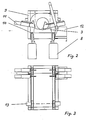
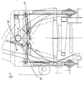
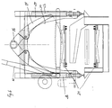
Im dargestellen Ausführungsbeispiel ist diese Hubeinrichtung entsprechend Fig. 5 aus einem auf einem Querbalken angeordneten Schubkolbengetriebe 14 gebildet, welches an einem mit dem Gelenk 15 eines Klemmbackenpaares verbundenen Hubarm 16 angreift. Daraus resultiert eine kleine Bauweise der Hubeinrichtung, die nur die Klemmbacken zu heben hat. Hierbei ist je Klemmbackenpaar ein Schubkolbengetriebe 14 vorgesehen. Die Klemmeinrichtung weist gemäß Fig. 4 zwei Klemmbackenpaare 17 und 18 auf, zwischen denen die Kappsäge 12 angeordnet ist. Die zwei Klemmbacken eines jeden Klemmbackenpaares 17, 18 sind an ihrem oberen Ende über ein Gelenk 15 miteinander verbunden, wobei unterhalb des Gelenkes die Enden von gleichfalls als Kolben-Zylindereinheiten ausgebildeten Schubkolbengetrieben 19, 20 angreifen, die die Klemmbacken in Klemmstellung fahren. Die Fig. 4 und 5 zeigen auch deutlich die Portalbauweise aus zwei unteren, die Räder aufnehmenden Längsbalken 21 und 22, vorderen und hinteren Ständern 23 bis 26 und oberen Längsbalken 27, 28, die durch obere Querbalken miteinander verbunden sind. Dadurch ergibt sich eine geschlossene und sehr steife Bauweise, wobei innerhalb des Portals die eigentlichen Arbeitsaggregate aufgenommen sind. Das Portal 9 ist hierbei zweckmäßigerweise als Vierkantrohrkonstruktion gebildet, wobei im Bereich der Ständer und Querbalken zumindest am vorderen und hinteren Ende des Portals Seitenwände 29 vorgesehen sind, die eine die Form eines umgekehrten U aufweisende Ausnehmung 30 für die Stammdurchführung aufweisen. Das Portal 9 trägt den Meßvorhang, die Kappsäge und die Klemmeinrichtung und besitzt einen Antrieb, wobei das Fahrwerk durch je zwei oder vier Räder auf den Längsbalken gebildet ist. Vorzugsweise sind zwei oder vier Aufsteckgetriebemotoren an den Rädern zur Aussteuerung über Frequenzumformer vorgesehen. Jeweils vor und nach jedem Rad kann ein Abstreifer angeordnet sein, der Verunreinigungen auf dem Gleis entfernt. Jeweils links und rechts vom Sägeblatt können alternativ zu den Klemmbackenpaaren im Vierkantrohr mit Kunststoffeinlage geführte Stamm-Klemmarme vorgesehen sein, die einzeln über Zylinder betätigbar sind. Die Zylinder können über Mengenteiler gekoppelt sein, der Unregelmäßigkeiten ausgleicht. Der Meßvorhang ist am Portal untergebracht und besitzt in einer Ausführungsform zwei vertikale gegenüberliegende Lichtleisten zur Bestimmung des vertikalen Stammdurchmessers. In einer weiteren Alternative können zusätzlich übereinander angeordnete horizontal oder diagonal ausgerichtete Lichtleisten vorgesehen sein, so daß der Stamm dann durch vier Lichtleisten geführt wird, wodurch auch der horizontale Durchmesser des Stammes gemessen werden kann.In the exemplary embodiment shown, this lifting device is formed according to FIG. 5 from a
Das Optimierungssystem mit dem Rechner kann auf dem Meß- und Ablängwagen angeordnet sein, wobei die Datenübertragung durch Funk auf das Bedienungssystem erfolgt, welches bevorzugt auf dem Holztransport- und -sortierwagen angeordnet ist. Anstelle einer Funkübertragung ist auch eine Datenlichtschranke möglich, wobei dann jedoch der Lichtsignalgeber auf dem Wagen geradlinig mit dem Empfänger ausgerichtet sein muß, von dem die Daten dann über Funk auf den Holztransportwagen übertragen werden. Alternativ kann das Optimierungssystem mit dem Computer auch außerhalb des Wagens angeordnet sein, wobei dann ein Schleppkabel oder eine Funkstrecke bzw. Datenlichtschranken zwischen dem Meßvorhang und dem Optimierungssystem vorhanden ist. Vorzugsweise ist ein eigenes Meßrad vorgesehen, über das die Messung mit einem Drehimpulsgeber erfolgt. Alternativ kann der Impulsgeber auch auf eines der nichtangetriebenen Räder des Wagens wirken. Wenn hierbei von Rädern gesprochen werden kann, ist es klar, daß es sich hier um schienenunabhängige Räder handeln kann, oder aber auch um Räder, die mit Schienen zusammenwirken.The optimization system with the computer can be arranged on the measuring and cutting trolley, the data being transmitted by radio to the operating system, which is preferably arranged on the wood transport and sorting trolley. Instead of a radio transmission, a data light barrier is also possible, but then the light signal transmitter on the carriage must be aligned in a straight line with the receiver, from which the data are then transmitted via radio to the wooden transport carriage. Alternatively, the optimization system with the computer can also be arranged outside the car, in which case a trailing cable or a radio link or data light barriers is present between the measuring curtain and the optimization system. A separate measuring wheel is preferably provided, via which the measurement is carried out with a rotary pulse encoder. Alternatively, the pulse generator can also act on one of the non-driven wheels of the car. If one can speak of wheels here, it is clear that these can be rail-independent wheels, or also wheels that interact with rails.
Der Stamm kann stationär auf der aus einer Profilstahlkonstruktion ausgebildeten Holzablage entsprechend Figur 4 und 5 liegen, über die der Meß- und Ablängwagen fährt. Bevorzugt dient ein Antrieb 31 für den Abtransport der abgetrennten Stammabschnitte.The trunk can be stationary on the wooden shelf made of a section steel construction according to FIGS. 4 and 5, over which the measuring and cutting car travels. A
Claims (10)
- A measuring and cross-cutting device for round timber in which long trunks of timber (1) are deposited by means of a mobile crane onto a fixed and stationary cross-cut holding bed (3) and are there measured for length and diameter, wherein the measurements are compared with a theoretical value stored within a computer and directly related to the particular contract being handled, and wherein, as a result of this comparison, optimised cross-cut lengths are obtained, characterised in that a remote-controlled measuring and cross-cutting carriage (4) is provided which is connected to the cross-cut holding bed (3) and is capable of operating along the total longitudinal extent of said holding bed, and on which are mounted all the measuring and cross-cutting units.
- A device according to claim 1, characterised in that the diameter measurements are effected in pre-selected sectional divisions along the whole length of the trunk and the measurement results are transferred to a computer which is located on or outside the measuring and cross-cutting carriage (4), and that, following the establishment of the dimensions of each respective trunk by comparison with the contract-specific theoretical values, optimised shaping options are suggested which are shown on a screen, preferably in the control cabin of a timber transporting vehicle, and are used to govern the remote control of the measuring and cross-cutting carriage.
- A device according to claim 1 or 2, characterised in that the data transference between the measuring and cross-cutting carriage, the computer and/or the timber transporting and selecting vehicle is effected by wireless radio communication or by a data light-signal box or by means of a cable.
- A device according to one of the preceding claims, characterised in that a swing saw (12) for cross-cutting the trunk, a measuring curtain (13) for establishing the diameter of the trunk and a clamping device (11) for holding the trunk during the cutting operation are arranged on the chassis frame of the measuring and cross-cutting carriage (4) and are controlled either automatically or manually from the timber transporting vehicle or excavating vehicle.
- A device according to claim 4, characterised in that an additional lifting device (14, 16) for raising the trunk during the cutting operation engages the clamping device (11).
- A device according to one of the preceding claims, characterised in that the measuring and cross-cutting carriage (4) is constructed in the form of a gantry and preferably comprises two lower longitudinal beams (21, 22) bearing the wheels and having upright forward and rearward pillars (23 to 26) which are connected to each other and to the gantry (9) by means of cross-beams and upper longitudinal beams (27, 28), wherein the measuring curtain, the swing saw and the clamping device are located preferably on the inside of the gantry.
- A device according to one of the preceding claims, characterised in that the clamping device comprises a pincer-shaped pair of clamping jaws (17, 18) located before and behind the swing saw (12), wherein the clamping jaws of each of the pairs are joined at their upper ends to a swivel joint (15) and each jaw is movable by means of a thrust piston drive unit (19, 20) which is preferably in the form of a piston-cylinder mechanism housed within the gantry (9) and which engages the jaw at a point below the swivel joint (15).
- A device according to claim 7, characterised in that the pairs of clamping jaws (17, 18) can be raised in the course of the cutting process either independently or together by means of a lifting device (14, 16) which raises or, as the case may be, lowers the pair of clamping jaws and preferably takes the form of a linear drive unit (14) constructed as a piston-cylinder which engages a lifting arm connected to the swivel joint (15).
- A device according to claim 8, characterised in that the linear drive (14) is arranged on a cross-beam linking the upper longitudinal beams (27, 28) or on the upper longitudinal beams.
- device according to one of the preceding claims, characterised in that the measuring curtain consists of two vertical inside-clearance fences or two vertical and two horizontal or diagonal inside-clearance fences between which the trunk lies during the measuring process.
Applications Claiming Priority (2)
| Application Number | Priority Date | Filing Date | Title |
|---|---|---|---|
| DE4223856 | 1992-07-20 | ||
| DE4223856 | 1992-07-20 |
Publications (2)
| Publication Number | Publication Date |
|---|---|
| EP0579898A1 EP0579898A1 (en) | 1994-01-26 |
| EP0579898B1 true EP0579898B1 (en) | 1997-07-30 |
Family
ID=6463651
Family Applications (1)
| Application Number | Title | Priority Date | Filing Date |
|---|---|---|---|
| EP93102172A Expired - Lifetime EP0579898B1 (en) | 1992-07-20 | 1993-02-11 | Measuring and cross cutting system for round timber |
Country Status (3)
| Country | Link |
|---|---|
| EP (1) | EP0579898B1 (en) |
| AT (1) | ATE156051T1 (en) |
| DE (1) | DE59306995D1 (en) |
Families Citing this family (1)
| Publication number | Priority date | Publication date | Assignee | Title |
|---|---|---|---|---|
| FR2726781A1 (en) * | 1994-11-15 | 1996-05-15 | Logsys | Log=handling and =cutting installation |
Family Cites Families (6)
| Publication number | Priority date | Publication date | Assignee | Title |
|---|---|---|---|---|
| US3771395A (en) * | 1968-06-28 | 1973-11-13 | C Heimerl | Log slasher |
| SE424160B (en) * | 1981-02-16 | 1982-07-05 | Hammars Mekaniska Verkstad Ab | PROCEDURE AND DEVICE FOR APPOINTING AND CUTTING STUMS AFTER DIMENSION Saturation |
| AT375863B (en) * | 1982-03-26 | 1984-09-25 | King Murphy Lavalin Inc | DEVICE FOR SAWING TRUNKS IN PIECES |
| US4468993A (en) * | 1982-06-11 | 1984-09-04 | International Paper Company | Small log bucking system |
| SE463086B (en) * | 1986-06-30 | 1990-10-08 | Interlog Ab | STOCKAPTERINGSANORDNING |
| US4901611A (en) * | 1989-03-30 | 1990-02-20 | Bentley Richard J | Apparatus and method for cutting mults from billets |
-
1993
- 1993-02-11 AT AT93102172T patent/ATE156051T1/en not_active IP Right Cessation
- 1993-02-11 DE DE59306995T patent/DE59306995D1/en not_active Expired - Fee Related
- 1993-02-11 EP EP93102172A patent/EP0579898B1/en not_active Expired - Lifetime
Also Published As
| Publication number | Publication date |
|---|---|
| DE59306995D1 (en) | 1997-09-04 |
| EP0579898A1 (en) | 1994-01-26 |
| ATE156051T1 (en) | 1997-08-15 |
Similar Documents
| Publication | Publication Date | Title |
|---|---|---|
| EP0053757A2 (en) | Apparatus to pull out and to push in tube bundles of heat exchangers | |
| DE102007010101A1 (en) | Method for producing a supply line duct and train consisting of vehicles for carrying out the method | |
| DE2817634C2 (en) | ||
| EP0727385B1 (en) | Mobile rail-crane | |
| DE3430002C2 (en) | ||
| DE2614921C3 (en) | Changing device for containers arranged in front of the discharge opening of a garbage compactor | |
| DD256158A5 (en) | VEHICLE APPARATUS FOR RECORDING OR LOCATING AND TRANSPORTING GLEISJOCHEN | |
| DE3409854C2 (en) | ||
| EP0579898B1 (en) | Measuring and cross cutting system for round timber | |
| DE2140901C3 (en) | Maneuvering device | |
| DE2228196A1 (en) | PROCEDURE AND ARRANGEMENT FOR RENEWAL OF RAILWAY SECTIONS | |
| DE1918599C3 (en) | Device for processing round wood | |
| DE2315648C2 (en) | Multi-storey car park | |
| AT403737B (en) | MEASURING SYSTEM FOR LONG OBJECTS, IN PARTICULAR WOOD TRUNKS | |
| DE2941611C2 (en) | ||
| DE2719727A1 (en) | Forklift transfer truck for transport loading station - has slewing lifting frame extending downwards from crab on travelling gantry with programme control | |
| DE2936160A1 (en) | Heavy weight lorry loading installation - uses loading machine equipped with conveyor consisting of load carriers and auxiliary sliders | |
| DE2529975A1 (en) | Mobile railway sleeper raising and laying machine - with advanced lengthways conveyor as endless roller mounted belt with suspension devices | |
| DE19625438A1 (en) | Mobile preparation machine, in particular screening machine, for ballast ballast in the railway system | |
| DD239817A5 (en) | RUNNING MACHINE WITH ROPE STOPPING UNIT | |
| DE2350988A1 (en) | Round timber transport carriage - has lifter and saw for cutting to length before ejection by push rods | |
| DE541003C (en) | Movable molding machine | |
| EP1752410A1 (en) | Industrial truck, particularly high portal truck | |
| DE801914C (en) | Method and device for conveying and stacking, in particular construction timber | |
| DE2009418A1 (en) | Method and device for the transport and, if necessary, for the interim storage of freight carriers by means of roller conveyors on freight carriers at transshipment points |
Legal Events
| Date | Code | Title | Description |
|---|---|---|---|
| PUAI | Public reference made under article 153(3) epc to a published international application that has entered the european phase |
Free format text: ORIGINAL CODE: 0009012 |
|
| AK | Designated contracting states |
Kind code of ref document: A1 Designated state(s): AT CH DE FR LI |
|
| 17P | Request for examination filed |
Effective date: 19940127 |
|
| 17Q | First examination report despatched |
Effective date: 19960118 |
|
| GRAG | Despatch of communication of intention to grant |
Free format text: ORIGINAL CODE: EPIDOS AGRA |
|
| GRAH | Despatch of communication of intention to grant a patent |
Free format text: ORIGINAL CODE: EPIDOS IGRA |
|
| GRAH | Despatch of communication of intention to grant a patent |
Free format text: ORIGINAL CODE: EPIDOS IGRA |
|
| GRAA | (expected) grant |
Free format text: ORIGINAL CODE: 0009210 |
|
| AK | Designated contracting states |
Kind code of ref document: B1 Designated state(s): AT CH DE FR LI |
|
| REF | Corresponds to: |
Ref document number: 156051 Country of ref document: AT Date of ref document: 19970815 Kind code of ref document: T |
|
| RIN1 | Information on inventor provided before grant (corrected) |
Inventor name: JECKLE, FRANZ Inventor name: BERTELE, GEBHARD |
|
| REG | Reference to a national code |
Ref country code: CH Ref legal event code: NV Representative=s name: AMMANN PATENTANWAELTE AG BERN Ref country code: CH Ref legal event code: EP |
|
| REF | Corresponds to: |
Ref document number: 59306995 Country of ref document: DE Date of ref document: 19970904 |
|
| ET | Fr: translation filed | ||
| PGFP | Annual fee paid to national office [announced via postgrant information from national office to epo] |
Ref country code: FR Payment date: 19980216 Year of fee payment: 6 |
|
| PGFP | Annual fee paid to national office [announced via postgrant information from national office to epo] |
Ref country code: AT Payment date: 19980219 Year of fee payment: 6 |
|
| PGFP | Annual fee paid to national office [announced via postgrant information from national office to epo] |
Ref country code: CH Payment date: 19980220 Year of fee payment: 6 |
|
| PGFP | Annual fee paid to national office [announced via postgrant information from national office to epo] |
Ref country code: DE Payment date: 19980420 Year of fee payment: 6 |
|
| PLBE | No opposition filed within time limit |
Free format text: ORIGINAL CODE: 0009261 |
|
| STAA | Information on the status of an ep patent application or granted ep patent |
Free format text: STATUS: NO OPPOSITION FILED WITHIN TIME LIMIT |
|
| 26N | No opposition filed | ||
| PG25 | Lapsed in a contracting state [announced via postgrant information from national office to epo] |
Ref country code: AT Free format text: LAPSE BECAUSE OF NON-PAYMENT OF DUE FEES Effective date: 19990211 |
|
| PG25 | Lapsed in a contracting state [announced via postgrant information from national office to epo] |
Ref country code: LI Free format text: LAPSE BECAUSE OF NON-PAYMENT OF DUE FEES Effective date: 19990228 Ref country code: CH Free format text: LAPSE BECAUSE OF NON-PAYMENT OF DUE FEES Effective date: 19990228 |
|
| REG | Reference to a national code |
Ref country code: CH Ref legal event code: PL |
|
| PG25 | Lapsed in a contracting state [announced via postgrant information from national office to epo] |
Ref country code: FR Free format text: LAPSE BECAUSE OF NON-PAYMENT OF DUE FEES Effective date: 19991029 |
|
| PG25 | Lapsed in a contracting state [announced via postgrant information from national office to epo] |
Ref country code: DE Free format text: LAPSE BECAUSE OF NON-PAYMENT OF DUE FEES Effective date: 19991201 |
|
| REG | Reference to a national code |
Ref country code: FR Ref legal event code: ST |