EP0579154B1 - Blattausrichtvorrichtung in einem Blattsortiergerät - Google Patents
Blattausrichtvorrichtung in einem Blattsortiergerät Download PDFInfo
- Publication number
- EP0579154B1 EP0579154B1 EP93111140A EP93111140A EP0579154B1 EP 0579154 B1 EP0579154 B1 EP 0579154B1 EP 93111140 A EP93111140 A EP 93111140A EP 93111140 A EP93111140 A EP 93111140A EP 0579154 B1 EP0579154 B1 EP 0579154B1
- Authority
- EP
- European Patent Office
- Prior art keywords
- sheet
- pin
- arm
- tray
- frictional member
- Prior art date
- Legal status (The legal status is an assumption and is not a legal conclusion. Google has not performed a legal analysis and makes no representation as to the accuracy of the status listed.)
- Expired - Lifetime
Links
Images


Classifications
-
- B—PERFORMING OPERATIONS; TRANSPORTING
- B65—CONVEYING; PACKING; STORING; HANDLING THIN OR FILAMENTARY MATERIAL
- B65H—HANDLING THIN OR FILAMENTARY MATERIAL, e.g. SHEETS, WEBS, CABLES
- B65H31/00—Pile receivers
- B65H31/34—Apparatus for squaring-up piled articles
Definitions
- the present invention relates to a sheet sorter for properly arranging sheets in the superimposed structure by displacing each sheet placed at a predetermined position on a -tray in a predetermined arranging direction. Further, the present invention relates to a sheet sorter having a sheet arranging device of the foregoing type accommodated therein.
- a conventional sheet arranging device having a sheet sorter accommodated therein for selectively sorting sheets on one of a plurality of trays is constructed such that a roller adapted to be rotationally driven by a motor is brought into contact with the upper surface of a sheet placed on the tray and the sheet is then displaced in a predetermined direction by rotating the roller so as to properly arrange sheets in the superimposed state.
- another conventional sheet arranging device of the foregoing type is constructed such that sheets placed on a tray are vibratively clapped by bars or similar members each extending across the opposite sides of the tray in the vertical direction until they are properly arranged on the tray in the superimposed state.
- Such a sheet sorter according to the preamble of claim 1 is known from EP-A-0 486 928.
- the present invention has been made in consideration of the aforementioned background.
- An object of the present invention is to provide a sheet sorter for selectively sorting sheets on one of a plurality of trays wherein a sheet arranging device which assures that sheets can properly be arranged in the superimposed state without fail while the whole structure of the sheet arranging device is designed with small dimensions and is accommodated in the sheet sorter.
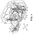
- a sorter housing 1 is arranged on the sheet discharging side of, e.g., a photoelectronic copying machine.
- each sheet passes between upper and lower guide plates 2A and 2B arranged in the sorter housing 1, and subsequently, passes between plural sets of feed rollers 3 and pinch rollers 4 so that it is transferred in the forward direction to reach a sheet outlet port (not shown) located at a predetermined position on the sorter housing 1.
- a sheet outlet port not shown
- the plurality of trays 5 are held on a tray carrier 6 in such a manner that each of the trays 5 is displaced in accordance with a predetermined order so as to receive the sheet discharged from the sheet outlet port on one of the trays 5 by way of raising/lowering of the whole tray carrier and retracting of each tray 5 in the rearward direction.
- An opposing pair of first vertically extending slots 7 and an opposing pair of second vertically extending slots 8, the intermediate part of which is bent in a substantially V-shaped curved state in the rearward direction, are formed on the left-hand and right-hand sides of the sorter housing 1.
- tray carrier 6 can slidably be displaced in the upward/downward direction relative to the sorter housing 1.
- resist pins 10 disposed on the tray carrier 6 on the opposite sides, dummy pins 11 disposed in the same way and rear tray pins 12 disposed on each of the trays 5 on the opposite sides are slidably fitted into the second slots 8 in accordance with the order as seen from above.
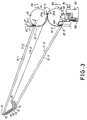
- a pair of upper and lower Geneva wheels 13 and 14 are simultaneously driven in the normal direction or in the reverse direction as shown in Fig.
- the trays 5 are retracted one by one in the rearward direction (in the rightward direction as seen in Fig. 3), whereby the distance between the retracted tray 5 and the tray 5 directly below the former is largely increased.
- Fig. 3 shows the state where a second tray 5-2 as counted from above is retracted in the rearward direction.
- the upper and lower Geneva wheels 13 and 14 are rotationally driven from the shown state such that the upper Geneva wheel 13 is rotated in the A 1 arrow-marked direction and the lower Geneva wheel 14 is rotated in the B 1 arrow-marked direction, a rear tray pin 12-2 on the second tray 5-2 is received in a groove 13A on the upper Geneva wheel 13 so that it is displaced along the second slot 8 in the A 1 arrow -marked direction.
- the Geneva wheels 13 and 14 are rotationally driven in synchronization with each other such that the upper Geneva wheel 13 is rotated in the A 1 arrow-marked direction and the lower Geneva wheel 14 is rotated in the B 1 arrow-marked direction in the same manner as mentioned above, the trays 5 are retracted in the rearward direction one by one as in the order as seen from above, whereby the gap between the retracted tray 5 and the tray 5 located directly below the former is largely increased, and at the same time, the tray carrier 6 is raised up by one stage.
- the Geneva wheels 13 and 14 are rotationally driven in synchronization with each other such that the upper Geneva wheel 13 is rotated in the A 2 arrow-marked direction and the lower Geneva wheel 14 is rotated in the B 2 arrow-marked direction, the trays 5 are retracted in the rearward direction one by one as reversely counted from below, whereby the gap between the retracted tray 5 and the tray 5 located directly below the former is largely increased, and at the same time, the tray carrier 6 is lowered by one stage.
- the sheet discharged from the copying machine is placed on the tray 5 located directly below the tray 5 which has been retracted in the rearward direction.
- the second tray 5-2 as counted from above is retracted as represented by solid lines in Fig. 3
- each sheet is placed on the third tray 5-3 located directly below the second tray 5-2.
- front tray pins 15 on each of the trays 5 on the opposite sides are displaceably fitted into substantially V-shaped guide grooves 16 formed on the opposite sides of the tray carrier 6.
- each tray 5 extends slantwise downwardly from the front side to the rear side, and moreover, it extends slantwise downwardly from the left-hand side (the LH side in Fig. 1) to the right-hand side (the RH side in Fig. 1).
- the sheet discharged on the tray 5 (identified by reference character S in Fig. 2) is slantwise slidably displaced toward a rear wall 5A and right-hand side walls 5B and 5C in the C arrow-marked direction.
- the sheet arranging device is accommodated in the sorter housing 1 to automatically properly arrange sheets successively placed on one of the trays 5.
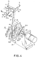
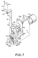
- reference numeral 31 designates a geared motor mounted in a device housing 30.
- An output shaft of the geared motor 31 is coupled to one end of a joint shaft 32.
- the intermediate part of the joint shaft 32 is rotatably supported in a vertical wall portion 30A, while the other end of the same is kept free.
- a substantially U-shaped cam 33 adapted to slidably receive one end of a first pin 37 to be described later is disposed at the free end of the joint shaft 32, and a substantially sector-shaped shading plate 34 is disposed on the outer peripheral surface of the joint shaft 32.
- the shading plate 34 serves to interrupt a light path between a light emitting element (not shown) disposed on one sensor base board 35A on the device housing 30 and a light receiving element (not shown) disposed on another sensor board 35B on the device housing 30 every time the joint shaft 32 is rotated.
- a controller detects that the joint shaft 32 is rotated to a predetermined rotational position.
- the foregoing detection signal is hereinafter referred to as "a rotational position detecting signal”.
- reference numeral 36 designates a substantially U-shaped movable member.
- the intermediate part of the first pin 37 is immovably fitted into the uppermost end of one arm portion 36A of the movable member 36.
- One end of the first pin 37 is slidably fitted into the substantially U-shaped cam 33, while the other end of the same is slidably fitted into a first parallelepiped-shaped guide groove 38 formed on a vertical wall portion 30B of the device housing 30.
- a groove portion corresponding to the lower side of the guide groove 38 is represented by an arranging direction groove portion 38A extending substantially in parallel with the sheet arranging direction to be described later.
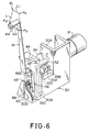
- the arm portion 36A of the movable member 36 is located between the two vertical wall portions 30B and 30C while coming into slidable contact with the vertical surfaces of the vertical wall portions 30B and 30C, a lower end part 36B of the same is kept freely movable in the space located below the vertical wall portion 30B, and another arm portion 36C of the same is located leftward of the vertical wall portion 30B as seen in Fig. 4.
- One end of a second pin 39 is immovably fitted into the lower end portion 36B of the movable member 36, while another end of the same is slidably fitted into a second guide groove 40 formed through a vertical wall portion 30D of the device housing 30.
- a longitudinally extending groove 36D having a T-shaped sectional contour is formed on the arm portion 36C of the movable member 36 so that a slider 42 fixedly secured to the base end of an arm 41 is slidably fitted into the guide groove 36D.
- a spring 43 for normally biasing the arm 41 toward the second pin 39 is spanned between the base end of the arm 41 and the arm portion 36C.
- the arm 41 is made of an elastic material, and a frictional member 44 having a concave curved lower surface molded of polyurethane rubber or a similar material is attached to the lower surface of a horizontal portion at the uppermost end of the arm 41.
- An inclined guide 45 the guide surface of which is inclined at a predetermined angle ⁇ 1 (see Fig. 4) as seen from above is formed on the upper surface side of the vertical wall portion 30B, and the intermediate part of the arm 41 is brought into close contact with the guide surface of the inclined guide 45 by the resilient power of the arm 41.
- the housing 30 of the sheet arranging device constructed in the above-described manner is received in the sorter housing 1 so that a sheet arranging operation to be described later is performed for a sheet placed on the tray 5 displaced to the sheet discharging position with the aid of the frictional member 44 disposed at the uppermost end of the arm 41.
- Each sheet arranging operation is repeatedly performed every time the cam 33 is rotated from a predetermined stop position in the D arrow-marked direction by a single revolution, and while the cam 33 is held at the predetermined stop position, a rotational position detecting signal is outputted from the controller.
- Fig. 5D illustrates the stated where the cam 33 is held at the stop position where the first pin 37 is raised up to a left upper corner of the first guide groove 38 by the action of the cam 33.
- the cam 33 is rotated from the foregoing stop position in the D arrow-marked direction by a single revolution, the first pin 37 is successively displaced to the right upper corner portion, the right lower corner portion and the left lower corner portion of the first guide groove 38 with the aid of the cam 33 as shown in Figs. 5A, 5B and 5C, and thereafter, the first pin 37 returns to the left upper corner of the first guide groove 38 as shown in Fig. 5D at which the movement of the first pin 37 is stopped.
- the second pin 39 is displaced along the second guide groove 40 in the upward/downward direction.
- the frictional member 44 disposed at the uppermost position of the arm 41 scribes a rectangular displacement locus L every time the cam 33 is rotated by a single revolution wherein the displacement locus L is started from a position P 0 shown in Fig. 5D (hereinafter referred to as waiting position) and returned to the waiting position P 0 via a position P 1 shown in Fig. 5A, a position P 2 shown in Fig. 5B and a position P 3 shown in Fig. 5C.
- the length of the displacement locus L 1 between the waiting position P 0 and the position P 1 is set to be longer than the distance of the displacement of the first pin 37 between the left upper corner portion and the right upper corner portion of the first guide groove 38 shown in Fig. 5A.
- the length of the displacement locus L 2 between the position P 2 and the position P 3 (corresponding to a length of the groove portion 38A as seen in the sheet arranging direction) is set to be larger than the distance of the displacement of the first pin 37 between the right lower corner portion and the left lower corner portion of the guide groove 38 shown in Fig. 5A.
- a quantity of displacement of the frictional member 44 is amplified by a ratio of the length between the second pin 39 and the frictional member 44 to the length between the first pin 37 and the second pin 39. This means that the frictional member 44 can largely be displaced even though the sheet arranging device is designed with small dimensions.
- the arm 41 is displaced while coming into close contact with the inclined guide 45.
- This causes both the loci L 1 and L 2 of the displacement of the frictional member 44 to be inclined by an angle corresponding to the inclination angle ⁇ 1 of the inclined guide 45 relative to the direction of extension of the rear wall 5A of the tray 5 as shown in Fig. 4.
- the locus L 2 of the displacement of the frictional member 44 is downwardly slantwise scribed toward a cutout portion 5D located at the corner portion defined between the rear wall 5A and the right-hand side wall 5B, the displacement position P 2 is located above the tray 5, and the displacement position P 3 is located in the positionally offset state away from the tray 5.
- the angle ⁇ 2 is coincident with the inclination angle of the locus L 2 of the displacement of the frictional member 44 as shown in Fig. 5A.
- the frictional member 44 is brought into contact with the upper surface of a sheet S at the displacement position P 2 , and as the frictional member 44 moves along the displacement locus L 2 , the sheet S is slidably displaced toward the cutout portion 5D in the presence of friction between the frictional member 44 and the sheet S until it collides against the rear wall 5A and the right-hand side walls 5B and 5C (see Fig. 2) for the purpose of properly arranging sheets S in the superimposed state.
- the frictional member 44 is located at the displacement position P 3 positionally offset away from the tray 5, and thereafter, it is raised up to the waiting position P 0 where it is held in the waiting state.
- the waiting position P 0 is determined to be coincident with the position where a raising/lowering operation and a retracting operation to be performed for the tray 5 are not obstructed at all. It should be noted that the arm 41 is increasingly displaced against the resilient force of the spring 43 (see Fig. 6) in the upward direction as the number of sheets S placed on the tray 5 in the superimposed state increases while the contact pressure of the frictional member 44 imparted to the sheet S is maintained within the predetermined range.
- a stapler may be mounted on the sorter housing 1 as desired so as to enable a stack of sheets S located at the cutout portion 5D of the tray (see Fig. 4) to be automatically stapled together.
Landscapes
- Engineering & Computer Science (AREA)
- Mechanical Engineering (AREA)
- Collation Of Sheets And Webs (AREA)
Claims (8)
- Blattsortierer mit:mehreren Fächern (5), die jeweils in die senkrechte Richtung verschiebbar sind,einer Fachverschiebeeinrichtung (6) zum selektiven Verschieben eines der mehreren Fächer (5) zu einer Blattausgabeposition,
ferner gekennzeichnet durch:einen Arm (41) mit einem an seinem obersten Ende angeordneten Reibungsglied (44), wobei das Reibungsglied (44) mit der Oberseite eines Blatts mit einer vorbestimmten Stärke der Reibungskraft in Berührung gebracht wird,eine erste Verschiebeeinrichtung (30, 36, 38, 40) zum senkrechten ringförmigen Verschieben des Reibungsglieds (44) um einen ersten Arbeitszustand oder einen zweiten Arbeitszustand einzunehmen, wobei der erste Arbeitszustand so ist, daß das Reibungsglied (44) mit der Oberseite des Blatts in Berührung gebracht wird, und der zweite Arbeitszustand so ist, daß das Reibungsglied (44) nicht mit der Oberseite des Blatts in Berührung gebracht wird, undeine Führungseinrichtung (38A, 45) zum Führen der Bewegung des Reibungsglieds (44), damit sich das Reibungsglied in eine vorbestimmte Richtung gegenüber den Fächern (5) bewegen kann. - Blattsortierer nach Anspruch 1, dadurch gekennzeichnet, daß die erste Verschiebeeinrichtung aufweist:einen Hauptkörper (30) mit einer ersten ringförmigen Führungsnut (38) und einer zweiten senkrecht verlaufenden Nut (40), die an ihm an vorbestimmten Positionen ausgebildet sind,ein bewegliches Glied (36), an dem der Arm (41) funktional befestigt ist, wobei das bewegliche Glied (36) einen ersten Stift (37) an einem Ende und einen zweiten Stift (39) an seinem anderen Ende aufweist, wobei der erste Stift (37) verschiebbar in der ersten Führungsnut (38) aufgenommen ist und der zweite Stift (39) verschiebbar in der zweiten Führungsnut (40) aufgenommen ist, undeine zweite Verschiebeeinrichtung (31, 33) zum verschieben des ersten Stifts (37) entlang der ersten Führungsnut (38).
- Blattsortierer nach Anspruch 2, dadurch gekennzeichnet, daß die zweite Verschiebeeinrichtung aufweist:eine U-förmige Nocke (33), die drehbar an dem Hauptkörper (30) gestützt ist, damit ein Ende des ersten Stifts (37) gleitend in die U-förmige Nocke (33) eingefügt werden kann, undeine Antriebseinrichtung (31) zum drehenden Antreiben der U-förmigen Nocke (33) in einer vorbestimmten Zeitbeziehung.
- Blattsortierer nach Anspruch 2 oder 3, dadurch gekennzeichnet, daß das bewegliche Glied (36) in der im wesentlichen U-förmigen Konfiguration mit einem ersten Armabschnitt (36A), an dem der erste Stift (37) angeordnet ist, einem Bodenabschnitt (36B), an dem der zweite Stift (39) angeordnet ist, und einem zweiten Armabschnitt (36C) gestaltet ist, und
dadurch gekennzeichnet, daß der Arm (41) an dem zweiten Armabschnitt (36C) über ein Gleitstück (42) angebracht ist, das geeignet ist, sich gleitend in die Längsrichtung zu bewegen. - Blattsortierer nach Anspruch 2, 3 oder 4, dadurch gekennzeichnet, daß die Führungseinrichtung aufweist:einen Nutenabschnitt (38A), der in dem Zwischenteil der ersten ringförmigen Führungsnut (38) ausgebildet ist, während er im wesentlichen parallel zu der vorbestimmten Richtung verläuft, undeine geneigte Führungsfläche (45), die an dem Hauptkörper (30) ausgebildet ist, damit das Zwischenteil des Arms (41) mit der geneigten Führungsfläche (45) in Berührung kommen kann.
- Blattsortierer nach Anspruch 4 oder 5, dadurch gekennzeichnet, daß der Arm (41) aus einem elastischen Material besteht und normalerweise zusammen mit dem Gleitstück (42) zu dem zweiten Stift (39) durch die Federkraft einer Feder (43) vorgespannt ist.
- Blattsortierer nach Anspruch 6, dadurch gekennzeichnet, daß die Führungseinrichtung aufweist:einen Nutenabschnitt (38A), der in dem Zwischenteil der ersten ringförmigen Führungsnut (38) ausgebildet ist, während er im wesentlichen entlang der vorbestimmten Richtung verläuft, undeine geneigte Führungsfläche (45), die an dem Hauptkörper (30) ausgebildet ist, damit das Zwischenteil des Arms (41) mit der geneigten Führungsfläche (45) in Berührung kommen kann.
- Blattsortierer nach einem der Ansprüche 2 bis 7, dadurch gekennzeichnet, daß der Abstand zwischen dem zweiten Stift (39) und dem Reibungsglied (44) so eingestellt ist, daß er größer als der zwischen dem ersten Stift (37) und dem zweiten Stift (39) ist.
Applications Claiming Priority (2)
| Application Number | Priority Date | Filing Date | Title |
|---|---|---|---|
| JP04185429A JP3088563B2 (ja) | 1992-07-13 | 1992-07-13 | シートの揃え装置およびソータ |
| JP185429/92 | 1992-07-13 |
Publications (3)
| Publication Number | Publication Date |
|---|---|
| EP0579154A2 EP0579154A2 (de) | 1994-01-19 |
| EP0579154A3 EP0579154A3 (de) | 1994-08-31 |
| EP0579154B1 true EP0579154B1 (de) | 1996-12-27 |
Family
ID=16170635
Family Applications (1)
| Application Number | Title | Priority Date | Filing Date |
|---|---|---|---|
| EP93111140A Expired - Lifetime EP0579154B1 (de) | 1992-07-13 | 1993-07-12 | Blattausrichtvorrichtung in einem Blattsortiergerät |
Country Status (4)
| Country | Link |
|---|---|
| US (1) | US5346204A (de) |
| EP (1) | EP0579154B1 (de) |
| JP (1) | JP3088563B2 (de) |
| DE (1) | DE69306873T2 (de) |
Families Citing this family (4)
| Publication number | Priority date | Publication date | Assignee | Title |
|---|---|---|---|---|
| KR0139041B1 (ko) * | 1995-01-12 | 1998-06-15 | 우석형 | 복사기용 소터, 배지정렬장치, 스태플링장치 및 이들을 이용한 스태플링 소터 |
| US5639078A (en) * | 1995-12-01 | 1997-06-17 | Xerox Corporation | Automatic sheet stacking edge registration members repositioning system with transverse tamper positioning |
| US6561504B2 (en) * | 2001-03-30 | 2003-05-13 | Lexmark International, Inc. | Finisher with single roller for frictionally moving each sheet |
| US6773004B2 (en) * | 2002-12-06 | 2004-08-10 | Hewlett-Packard Development Company, L.P. | Methods and apparatus to estimate the thickness of a sheet stack |
Family Cites Families (11)
| Publication number | Priority date | Publication date | Assignee | Title |
|---|---|---|---|---|
| US4319743A (en) * | 1980-02-11 | 1982-03-16 | International Business Machines Corp. | Two-direction rotary paper aligner |
| US4500085A (en) * | 1983-04-14 | 1985-02-19 | Burroughs Corporation | Oscillating wheel paper item stacking apparatus |
| JPS62244869A (ja) * | 1986-04-15 | 1987-10-26 | Ricoh Co Ltd | ステイプラ移動装置を具備するソ−タ |
| JPS6347265A (ja) * | 1986-08-08 | 1988-02-29 | Hitachi Koki Co Ltd | シ−ト類の仕分け機構 |
| JPS63267660A (ja) * | 1987-04-21 | 1988-11-04 | Canon Inc | シ−ト後処理装置 |
| JPH01317957A (ja) * | 1988-03-08 | 1989-12-22 | Ricoh Co Ltd | 排紙スタッカー装置 |
| JPH01236163A (ja) * | 1988-03-12 | 1989-09-21 | Canon Inc | シート後処理装置 |
| US5020785A (en) * | 1988-07-14 | 1991-06-04 | Ikegami Tsushiniki Co. Ltd. | Sheet finisher |
| US5088721A (en) * | 1990-07-10 | 1992-02-18 | Ikegami Tsushinki Co., Ltd. | Transporting device and sorter with the same |
| JP2873728B2 (ja) * | 1990-07-28 | 1999-03-24 | ニスカ株式会社 | ステップリング機構付きソータ及びステップリング機構付きソータにおけるステップリング方法 |
| JPH0813583B2 (ja) * | 1990-11-15 | 1996-02-14 | 三田工業株式会社 | ソータ |
-
1992
- 1992-07-13 JP JP04185429A patent/JP3088563B2/ja not_active Expired - Fee Related
-
1993
- 1993-07-08 US US08/087,323 patent/US5346204A/en not_active Expired - Fee Related
- 1993-07-12 DE DE69306873T patent/DE69306873T2/de not_active Expired - Fee Related
- 1993-07-12 EP EP93111140A patent/EP0579154B1/de not_active Expired - Lifetime
Also Published As
| Publication number | Publication date |
|---|---|
| US5346204A (en) | 1994-09-13 |
| EP0579154A2 (de) | 1994-01-19 |
| DE69306873D1 (de) | 1997-02-06 |
| JPH0632525A (ja) | 1994-02-08 |
| DE69306873T2 (de) | 1997-05-07 |
| EP0579154A3 (de) | 1994-08-31 |
| JP3088563B2 (ja) | 2000-09-18 |
Similar Documents
| Publication | Publication Date | Title |
|---|---|---|
| EP0439032B1 (de) | Sortiergerät | |
| EP0579154B1 (de) | Blattausrichtvorrichtung in einem Blattsortiergerät | |
| EP0807499B1 (de) | Elektroheftgerät | |
| EP0259829B1 (de) | Sortiermaschine | |
| US5067036A (en) | Cassette loading mechanism for accommodating cassettes of various sizes | |
| CA1204799A (en) | Alignment restraint station | |
| US4611800A (en) | Sheet separator apparatus for recirculating feeder | |
| CA1217518A (en) | Enhanced envelope feeding | |
| US11518640B2 (en) | Medium discharge device, medium processing apparatus, and recording system | |
| JPS62211265A (ja) | シ−ト排紙受け装置 | |
| EP1136403B1 (de) | Unterscheidungsvorrichtung | |
| US5158275A (en) | Multiple tray rotary paper feed system for an image reproduction machine | |
| EP0259830B1 (de) | Sortiermaschine | |
| EP0437646B1 (de) | Sortiermaschine | |
| US4916481A (en) | Copying apparatus with original document positioning and guiding arrangement | |
| JP2565364B2 (ja) | シート分類装置 | |
| JPH0626984B2 (ja) | 給紙カセツト構造 | |
| EP0465762B1 (de) | Sortiereinheit für Artikel mit einer Pressvorrichtung | |
| JP3593830B2 (ja) | 画像形成装置の後処理装置 | |
| US5082257A (en) | Sorter | |
| JPH061517A (ja) | コピースタック装置 | |
| JP3398175B2 (ja) | カード体供給装置 | |
| JPH0711076Y2 (ja) | 丁合装置 | |
| JPH0624578A (ja) | シート積載装置 | |
| JPH0671979B2 (ja) | シート分類装置 |
Legal Events
| Date | Code | Title | Description |
|---|---|---|---|
| PUAI | Public reference made under article 153(3) epc to a published international application that has entered the european phase |
Free format text: ORIGINAL CODE: 0009012 |
|
| 17P | Request for examination filed |
Effective date: 19930804 |
|
| AK | Designated contracting states |
Kind code of ref document: A2 Designated state(s): DE FR GB |
|
| PUAL | Search report despatched |
Free format text: ORIGINAL CODE: 0009013 |
|
| AK | Designated contracting states |
Kind code of ref document: A3 Designated state(s): DE FR GB |
|
| 17Q | First examination report despatched |
Effective date: 19950208 |
|
| GRAH | Despatch of communication of intention to grant a patent |
Free format text: ORIGINAL CODE: EPIDOS IGRA |
|
| GRAH | Despatch of communication of intention to grant a patent |
Free format text: ORIGINAL CODE: EPIDOS IGRA |
|
| GRAA | (expected) grant |
Free format text: ORIGINAL CODE: 0009210 |
|
| AK | Designated contracting states |
Kind code of ref document: B1 Designated state(s): DE FR GB |
|
| REF | Corresponds to: |
Ref document number: 69306873 Country of ref document: DE Date of ref document: 19970206 |
|
| ET | Fr: translation filed | ||
| PLBE | No opposition filed within time limit |
Free format text: ORIGINAL CODE: 0009261 |
|
| STAA | Information on the status of an ep patent application or granted ep patent |
Free format text: STATUS: NO OPPOSITION FILED WITHIN TIME LIMIT |
|
| 26N | No opposition filed | ||
| PGFP | Annual fee paid to national office [announced via postgrant information from national office to epo] |
Ref country code: GB Payment date: 20000623 Year of fee payment: 8 |
|
| PGFP | Annual fee paid to national office [announced via postgrant information from national office to epo] |
Ref country code: FR Payment date: 20000718 Year of fee payment: 8 |
|
| PGFP | Annual fee paid to national office [announced via postgrant information from national office to epo] |
Ref country code: DE Payment date: 20000929 Year of fee payment: 8 |
|
| PG25 | Lapsed in a contracting state [announced via postgrant information from national office to epo] |
Ref country code: GB Free format text: LAPSE BECAUSE OF NON-PAYMENT OF DUE FEES Effective date: 20010712 |
|
| GBPC | Gb: european patent ceased through non-payment of renewal fee |
Effective date: 20010712 |
|
| PG25 | Lapsed in a contracting state [announced via postgrant information from national office to epo] |
Ref country code: FR Free format text: LAPSE BECAUSE OF NON-PAYMENT OF DUE FEES Effective date: 20020329 |
|
| PG25 | Lapsed in a contracting state [announced via postgrant information from national office to epo] |
Ref country code: DE Free format text: LAPSE BECAUSE OF NON-PAYMENT OF DUE FEES Effective date: 20020501 |
|
| REG | Reference to a national code |
Ref country code: FR Ref legal event code: ST |