EP0572474B1 - Abschnürvorrichtung für körperteile - Google Patents
Abschnürvorrichtung für körperteile Download PDFInfo
- Publication number
- EP0572474B1 EP0572474B1 EP92905065A EP92905065A EP0572474B1 EP 0572474 B1 EP0572474 B1 EP 0572474B1 EP 92905065 A EP92905065 A EP 92905065A EP 92905065 A EP92905065 A EP 92905065A EP 0572474 B1 EP0572474 B1 EP 0572474B1
- Authority
- EP
- European Patent Office
- Prior art keywords
- receiving channel
- constriction
- web
- vein
- fixing
- Prior art date
- Legal status (The legal status is an assumption and is not a legal conclusion. Google has not performed a legal analysis and makes no representation as to the accuracy of the status listed.)
- Expired - Lifetime
Links
Images
Classifications
-
- A—HUMAN NECESSITIES
- A61—MEDICAL OR VETERINARY SCIENCE; HYGIENE
- A61M—DEVICES FOR INTRODUCING MEDIA INTO, OR ONTO, THE BODY; DEVICES FOR TRANSDUCING BODY MEDIA OR FOR TAKING MEDIA FROM THE BODY; DEVICES FOR PRODUCING OR ENDING SLEEP OR STUPOR
- A61M5/00—Devices for bringing media into the body in a subcutaneous, intra-vascular or intramuscular way; Accessories therefor, e.g. filling or cleaning devices, arm-rests
- A61M5/42—Devices for bringing media into the body in a subcutaneous, intra-vascular or intramuscular way; Accessories therefor, e.g. filling or cleaning devices, arm-rests having means for desensitising skin, for protruding skin to facilitate piercing, or for locating point where body is to be pierced
- A61M5/425—Protruding skin to facilitate piercing, e.g. vacuum cylinders, vein immobilising means
-
- A—HUMAN NECESSITIES
- A61—MEDICAL OR VETERINARY SCIENCE; HYGIENE
- A61B—DIAGNOSIS; SURGERY; IDENTIFICATION
- A61B17/00—Surgical instruments, devices or methods
- A61B17/12—Surgical instruments, devices or methods for ligaturing or otherwise compressing tubular parts of the body, e.g. blood vessels or umbilical cord
- A61B17/132—Tourniquets
- A61B17/1322—Tourniquets comprising a flexible encircling member
- A61B17/1327—Tensioning clamps
Definitions
- the present invention relates to a pinching device for body parts according to the preamble of claim 1.
- Pinch devices of this type are used in medicine to block a patient's vein before venipuncture.
- these known constriction devices blood congestion is created in the vein, but the vein is not fixed.
- the phenomenon of the roller vein which is an age-related weakness of the connective tissue, through which the veins move loosely in the subcutaneous tissue, is known in particular in older patients. With such roller veins, venipuncture is often not possible or only with great difficulty.
- the present invention is therefore based on the object of creating a constriction device of the type mentioned at the outset, which is placed around the extremity of the patient, by means of which not only congestion in the body part but also fixation of the vein is possible.
- the invention advantageously provides a constriction device with a fixation device for veins, which solves the problem of the roller veins, in that the fixation device contains a receiving channel for the veins. When the body part is tied off, the receiving channel surrounds the vein and fixes it against sliding away.
- the constriction device has a fixing device which is connected at one point to the circumferentially adjustable constriction means which is placed around the extremity and which has a gap with a width sufficient to fix a vein. After the constriction device has been put on and tightened, the fixing device is consequently pressed onto the arm or leg of the patient, the constriction device being attached such that the vein to be punctured lies in the gap of the fixing device and is thereby fixed.
- the fixing device is attached to the lock part. In this way, the fixing device can be positioned with the lock part, which facilitates the handling of the constriction device.
- the fixing device can receive one end of the constriction means on one side and have a closure part on the side opposite this end, which can be snapped into the lock part. This simplifies the application of the constricting device, since the constricting means with the fixing device at the end of the band can be placed around the body part to be tied in a simple manner, by snapping into place the fixing device in the lock part the loop is closed around the body part and then the loop can be tensioned.
- the gap of the fixing device on one side is open to the edge of the fixing device, whereas the gap on the other side ends at a distance from the edge of the fixing device, so that there remains a kind of web of the fixing device, which the two halves of the fixing device lying to the right and left of the gap.
- This web is arched upwards, so that a kind of tunnel-like free space remains under the web after the constriction device has been put on between the underside of the fixing device and the extremity of the patient.
- the vein to be punctured is itself only fixed and not blocked, but the veins in the vicinity of this vein are blocked, so that the fixed vein is increasingly flowed through with blood due to the increased blood flow and can therefore be punctured well.
- the constriction device or the fixing device can also be combined with a pivotable receiving channel.
- the pivoting of the receiving channel can be achieved either by means of a pivotable fixing device or by means of ends of the constriction means which are pivotally attached to the fixing device, or by means of a receiving channel which can be pivoted within the fixing device.
- the fixing device can be circular in outline at least in partial areas of its circumference, preferably the attachment points of the Limb means that can be placed on the extremity of the fixing device can be displaced along a circular path at least over a certain circular arc region. This makes it possible to rotate the fixing device relative to the constriction means and thus to bring it into a position in which the vein runs in the gap of the fixing device.
- the width of the fixing device gap can be adjusted.
- this can be solved, for example, by producing the fixing device from two sub-plates which are connected to one another and are displaceable relative to one another, so that the gap width of the receiving channel changes. This enables the gap width to be adapted to the width of the vein.
- the fixing device can be slightly curved on its underside, to be precise in accordance with the shape of the limb to which the constriction device is applied, as a result of which the application of the fixing device to the respective part of the patient's body is improved.
- Different fixing devices for exchanging for certain applications can advantageously be provided.
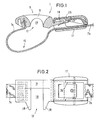
- the one-piece fixing device 9 can have an open receiving channel 12, as shown in FIGS. 1 and 2, which does not interrupt the blood flow through the vein enclosed in the gap 10, or have a receiving channel 12 closed on one side, which is formed in that the receiving channel 12 bridging web 11 extends to the lower edge of the fixing device 9 on the body side.
- the fixing device 9 can have two projections 28 projecting on one side of the band 7, which abut directly on the body part and leave the gap 10 of the receiving channel 12 between them.
- This exemplary embodiment can also have a receiving channel 12 which can be pivoted in the plane of the band 7.
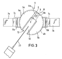
- FIG. 3 a rotatable fixing device 9 of a constricting device 1 is shown on a somewhat enlarged scale.
- the fixing device 9 is predominantly circular in outline and consists of two approximately mirror-symmetrical partial plates 5a, 5b which are joined together in the web area 11 of the fixing device.
- the fixing device 9 has a gap 10 that is approximately rectangular or U-shaped in cross-section, which extends radially and is open to the outside on one edge of the fixing device and which extends in length over approximately two thirds of the diameter of the fixing device.
- the width of the gap 10 is variable in that the two partial plates 5a, 5b are mutually displaceable in the area of the web 11, a locking screw 3 being provided, by means of which the two partial plates in the respective position with the desired gap width, which varies according to the The width of the vein is aligned and fixable.
- the ends 7a, 7b of a constriction means in the form of a band are fastened to fastening eyes 6 on the circumference of the fixing device 9.
- the fixing device 9 can be brought into a desired position in which the vein to be punctured lies in the gap 10
- circumferential sliding rails 4a, 4b in the form of undercut grooves are formed on the partial plates 5a, 5b, which form towards the end face of the partial plates 5a , 5b are open so that a continuous gap is formed in the partial plates at the front (see FIG. 3).
- the fastening eyes 6a, 6b, to which the loops 7c of the band ends 7a, 7b are fastened, have on the side facing the fixing device each formations that are received by the slide rails 4a, 4b. In this way, the fastening eyes 6a, 6b can be moved in these slide rails 4a, 4b along a circular guideway.
- the slide rails 4a, 4b each extend over a partial area of the circumference of the partial plates 5a, 5b.
- the slide rails 4a, 4b can, for example, each end at a slight distance in front of the gap 10 and extend over the area of curvature of the partial plates 5a, 5b to approximately in the vicinity of the straight web area 11.
- the fixing device 9 can thus be rotated about its axis relative to the band ends 7a, 7b until the vein to be punctured lies in the gap 10 and extends in the direction of the gap. Such a position with the fixing device rotated is shown in FIG. 3.
- the jammed or inflated vein can now be punctured using the injection needle 23.
- the preferably provided possibility of displacing the two partial plates 5a, 5b against one another and thus changing the width of the gap 10 is clear from FIGS. 1 and 2.
- the lower part plate 5a is bent in the web part 11a at the outer edges by about 180 °, so that there is a kind of guide rail 2 at the edges, which receives the web part 11b of the part plate 5b.
- the edges of the partial plate 5a encompass the edge of the partial plate 5b, which pushes over the partial plate 5a in the web area and is guided in the guide rail 2 formed on the partial plate 5a during this displacement movement.
- the gap 10 can, for example, be set to a width of approximately 8 mm in the normal case and adjusted depending on the size of the vein to be punctured.
- the flanks 8 of the receiving channel 12 which keeps the gap 10 free can run obliquely, so that the gap 10, seen in cross section, narrows conically towards the body part.
Landscapes
- Health & Medical Sciences (AREA)
- Vascular Medicine (AREA)
- Life Sciences & Earth Sciences (AREA)
- Animal Behavior & Ethology (AREA)
- Veterinary Medicine (AREA)
- Public Health (AREA)
- Surgery (AREA)
- Engineering & Computer Science (AREA)
- Biomedical Technology (AREA)
- Heart & Thoracic Surgery (AREA)
- General Health & Medical Sciences (AREA)
- Molecular Biology (AREA)
- Medical Informatics (AREA)
- Nuclear Medicine, Radiotherapy & Molecular Imaging (AREA)
- Reproductive Health (AREA)
- Dermatology (AREA)
- Anesthesiology (AREA)
- Hematology (AREA)
- Surgical Instruments (AREA)
- External Artificial Organs (AREA)
- Materials For Medical Uses (AREA)
- Vehicle Interior And Exterior Ornaments, Soundproofing, And Insulation (AREA)
- Orthopedics, Nursing, And Contraception (AREA)
Description
- Die vorliegende Erfindung betrifft eine Abschnürvorrichtung für Körperteile nach dem Oberbegriff des Anspruchs 1.
- Abschnürvorrichtungen dieser Art (EP-A 0 375 901) werden in der Medizin verwendet, um eine Vene des Patienten vor einer Venenpunktion zu stauen. Bei diesen bekannten Abschnürvorrichtungen wird zwar ein Blutstau in der Vene erzeugt, es erfolgt jedoch keine Fixierung der Vene. Insbesondere bei älteren Patienten ist das Phänomen der Rollvene bekannt, bei dem es sich um eine alters bedingte Bindegewebsschwäche handelt, durch die die Venen sich locker im Unterhautgewebe bewegen. Bei solchen Rollvenen ist eine Venenpunktion oft nicht oder nur unter großen Schwierigkeiten möglich.
- Der vorliegenden Erfindung liegt daher die Aufgabe zugrunde, eine Abschnürvorrichtung der eingangs genannten Art, die um die Extremität des Patienten gelegt wird, zu schaffen, mittels derer nicht nur eine Stauung im Körperteil, sondern gleichzeitig auch eine Fixierung der Vene möglich ist.
- Zur Lösung dieser Aufgabe dienen erfindungsgemaß die Merkmale des Anspruchs 1.
- Die Erfindung schafft in vorteilhafter Weise eine Abschnürvorrichtung mit einer Fixiereinrichtung für Venen, die das Problem der Rollvenen löst, indem die Fixiereinrichtung einen Aufnahmekanal für die Venen enthält. Der Aufnahmekanal faßt beim Abschnüren des Körperteils die Vene ein und fixiert diese gegen Weggleiten.
- Die Abschnürvorrichtung weist eine Fixiereinrichtung aufweisen, die an einer Stelle mit dem im Umfang einstellbaren Abschnürmittel, das um die Extremität gelegt wird, verbunden ist und die einen Spalt mit einer zur Fixierung einer Vene ausreichenden Breite aufweist. Nach dem Anlegen und Festziehen der Abschnürvorrichtung wird folglich die Fixiereinrichtung an den Arm oder das Bein des Patienten angepreßt, wobei die Abschnürvorrichtung so angebracht wird, daß die zu punktierende Vene in dem Spalt der Fixiereinrichtung liegt und dadurch fixiert wird.
- Die Fixiereinrichtung ist an dem Schloßteil befestigt. Auf diese Weise kann die Fixiereinrichtung mit dem Schloßteil positioniert werden, was die Handhabung der Abschnürvorrichtung erleichtert.
- Dabei kann die Fixiereinrichtung auf einer Seite das eine Ende des Abschnürmittels aufnehmen und auf der diesem Ende gegenüberliegenden Seite ein Verschlußteil aufweisen, das in dem Schloßteil einrastbar ist. Dadurch ist das Anlegen der Abschnürvorrichtung vereinfacht, da das Abschnürmittel mit der Fixiereinrichtung am Ende des Bandes in einfacher Weise um das abzubindende Körperteil gelegt werden kann, wobei durch das Einrasten der Fixiereinrichtung in dem Schloßteil die Schlinge um das Körperteil geschlossen wird und anschließend die Schlinge gespannt werden kann.
- Es ist vorgesehen, daß der Spalt der Fixiereinrichtung auf einer Seite nach außen zum Rand der Fixiereinrichtung hin offen ist, wohingegen der Spalt auf der anderen Seite mit Abstand vom Rand der Fixiereinrichtung endet, so daß dort eine Art Steg der Fixiereinrichtung stehenbleibt, der die beiden rechts und links des Spaltes liegenden Hälften der Fixiereinrichtung verbindet. Dieser Steg ist nach oben hin aufgewölbt, so daß nach dem Anlegen der Abschnürvorrichtung zwischen der Unterseite der Fixiereinrichtung und der Extremität des Patienten unter dem Steg eine Art tunnelartiger Freiraum verbleibt.
- Die zu punktierende Vene wird selbst nur fixiert und nicht gestaut, die Venen in der Umgebung dieser Vene werden aber gestaut, so daß die fixierte Vene durch den erhöhten Blutrückfluß verstärkt mit Blut durchflossen wird und dadurch gut punktiert werden kann.
- Die Abschnürvorrichtung bzw. die Fixiereinrichtung kann auch mit einem schwenkbaren Aufnahmekanal kombiniert sein. Die Schwenkbarkeit des Aufnahmekanals kann dabei entweder durch eine schwenkbare Fixiereinrichtung erreicht werden oder durch schwenkbar an der Fixiereinrichtung befestigte Enden des Abschnürmittels, oder durch einen innerhalb der Fixiereinrichtung schwenkbaren Aufnahmekanal.
- Die Fixiereinrichtung kann zumindest in Teilbereichen ihres Umfangs im Umriß kreisrund ausgebildet sein, wobei vorzugsweise die Befestigungspunkte des um die Extremität legbaren Abschnürmittel am Umfang der Fixiereinrichtung entlang einer Kreisbahn zumindest über einen gewissen Kreisbogenbereich verschiebbar sind. Dadurch ist es möglich, die Fixiereinrichtung gegenüber dem Abschnürmittel zu verdrehen und so in eine Position zu bringen, in der die Vene in dem Spalt der Fixiereinrichtung verläuft.
- Weiter ist es vorzugsweise vorgesehen, daß der Spalt der Fixiereinrichtung in seiner Breite einstellbar ist. Dies kann technisch zum Beispiel so gelöst werden, daß man die Fixiereinrichtung aus zwei miteinander verbundenen und gegeneinander verschiebbaren Teilplatten herstellt, so daß sich die Spaltbreite des Aufnahmekanals verändert. Dies ermöglicht es, die Spaltbreite der Breite der Vene anzupassen.
- Es bietet sich weiterhin an, das eine Ende des Abschnürmittels, vorzugsweise ein Band an der Fixiereinrichtung jeweils lösbar zu befestigen, so daß das Band bei Verschmutzungen ausgewechselt werden kann. Außerdem kann die Fixiereinrichtung an ihrer Unterseite etwas gewölbt sein und zwar entsprechend der Form der Gliedmaße, an die die Abschnürvorrichtung angelegt wird, wodurch das Anlegen der Fixiereinrichtung an dem jeweiligen Körperteil des Patienten verbessert wird. Unterschiedliche Fixiereinrichtungn zum Auswechseln für bestimmte Anwendungsfälle können vorteilhaft vorgesehen sein.
- Im folgenden werden Ausführungsbeispiele der Erfindung unter Bezugnahme auf die Zeichnungen näher erläutert.
- Es zeigen:
- Fig. 1
- eine mit einem Schloßteil gekoppelte Fixiereinrichtung;
- Fig. 2
- eine Draufsicht auf das Ausführungsbeispiel der Fig. 1;
- Fig. 3
- eine Draufsicht auf eine verdrehbare Fixiereinrichtung;
- Die einstückige Fixiereinrichtung 9 kann dabei einen wie in den Figuren 1 und 2 dargestellt offenen Aufnahmekanal 12 aufweisen, der den Blutdurchfluß durch die in dem Spalt 10 eingefaßte Vene nicht unterbricht oder einen einseitig geschlossenen Aufnahmekanal 12 haben, der dadurch gebildet ist, daß der den Aufnahmekanal 12 überbrückende Steg 11 bis zur körperseitigen Unterkante der Fixiereinrichtung 9 verläuft. Die Fixiereinrichtung 9 kann zwei einseitig des Bandes 7 vorstehende Vorsprünge 28 aufweisen, die unmittelbar auf dem Körperteil anliegen und zwischen sich den Spalt 10 des Aufnahmekanals 12 freilassen.
- Dieses Ausführungsbeispiel kann auch einen in der Ebene des Bandes 7 schwenkbaren Aufnahmekanal 12 aufweisen.
- Zur Erläuterung der Schwenkbarkeit des Aufnahmekanals 12 wird auf Fig. 3 Bezug genommen, in der eine drehbare Fixiereinrichtung 9 einer Abschnürvorrichtung 1 in etwas vergrößertem Maßstab dargestellt ist. In dem Ausführungsbeispiel ist die Fixiereinrichtung 9 im Umriß überwiegend kreisrund gestaltet und besteht aus zwei etwa spiegelsymmetrischen Teilplatten 5a, 5b, die im Stegbereich 11 der Fixiereinrichtung zusammengefügt sind. Die Fixiereinrichtung 9 weist einen im Querschnitt etwa rechteckigen oder U-förmigen Spalt 10 auf, der sich radial erstreckt und zum einen Rand der Fixiereinrichtung hin nach außen offen ist und der sich in der Länge in etwa über zwei Drittel des Durchmessers der Fixiereinrichtung erstreckt. Die Breite des Spalts 10 ist dadurch variabel, daß die beiden Teilplatten 5a, 5b im Bereich des Stegs 11 gegeneinander verschiebbar sind, wobei eine Feststellschraube 3 vorgesehen ist, mittels derer die beiden Teilplatten in der jeweiligen Position mit der gewünschten Spaltbreite, die sich nach der Breite der Vene richtet, fixierbar sind. Auf der linken bzw. rechten Seite der Fixiereinrichtung 9 in Fig. 3 sind am Umfang der Fixiereinrichtung 9 jeweils die Enden 7a, 7b eines Abschnürmittels in Form eines Bandes an Befestigungsösen 6 befestigt.
- Damit die Fixiereinrichtung 9 in eine gewünschte Lage bringbar ist, in der die zu punktierende Vene in dem Spalt 10 liegt, sind an den Teilplatten 5a, 5b am Umfang umlaufend Gleitschienen 4a, 4b in Form von hinterschnittenen Nuten ausgebildet, die zur Stirnseite der Teilplatten 5a, 5b hin offen sind, so daß stirnseitig ein durchgehender Spalt in den Teilplatten gebildet ist (s. Fig. 3). Die Befestigungsösen 6a, 6b, an denen die Schlaufen 7c der Bandenden 7a, 7b befestigt werden, weisen an der der Fixiereinrichtung zugewandten Seite jeweils Anformungen auf, die von den Gleitschienen 4a, 4b aufgenommen werden. Auf diese Weise sind die Befestigungsösen 6a, 6b in diesen Gleitschienen 4a, 4b entlang einer kreislinienförmigen Führungsbahn verschiebbar. Es ist ausreichend, wenn sich die Gleitschienen 4a, 4b jeweils über einen Teilbereich des Umfangs der Teilplatten 5a, 5b erstrecken. Die Gleitschienen 4a, 4b können beispielsweise jeweils mit etwas Abstand vor dem Spalt 10 enden und sich über den Krümmungsbereich der Teilplatten 5a, 5b bis etwa in Nähe des geradlinigen Stegbereichs 11 erstrecken. Die Fixiereinrichtung 9 kann somit gegenüber den Bandenden 7a, 7b um ihre Achse verdreht werden, bis die zu punktierende Vene in dem Spalt 10 liegt und in Spaltrichtung verläuft. Eine derartige Position mit verdrehter Fixiereinrichtung ist in Fig. 3 dargestellt. Die gestaute bzw. aufgeblähte Vene kann nun mit nun mittels der Injektionsnadel 23 punktiert werden.
- Die vorzugsweise vorgesehene Möglichkeit, die beiden Teilplatten 5a, 5b gegeneinander zu verschieben und damit die Breite des Spalts 10 zu verändern, wird aus den Figuren 1 und 2 deutlich. Die untere Teilplatte 5a ist im Stegteil 11a an den äußeren Rändern um etwa 180° umgebogen ist, so daß sich an den Rändern eine Art Führungsschiene 2 ergibt, die den Stegteil 11b der Teilplatte 5b aufnimmt. Die Ränder der Teilplatte 5a umgreifen im Bereich des Stegs 11 den Rand der Teilplatte 5b, die sich im Stegbereich über die Teilplatte 5a schiebt und bei dieser Verschiebbewegung in der an der Teilplatte 5a gebildeten Führungsschiene 2 geführt wird. Der Spalt 10 kann beispielsweise auf eine Breite von ca. 8 mm im Normalfall eingestellt und je nach Größe der zu punktierenden Vene verstellt werden. Ist die gewünschte Spaltbreite eingestellt, werden die beiden Teilplatten 5a, 5b mittels der Feststellschraube 3 im Stegbereich fixiert. Die Flanken 8 des den Spalt 10 freihaltenden Aufnahmekanals 12 können schräg verlaufen, so daß der Spalt 10 im Querschnitt gesehen sich zum Körperteil konisch verengt.
Claims (8)
- Abschnürvorrichtung für Körperteile mit einem ein Körperteil umfassendes, eine Schlinge (15) bildendes Abschnürmittel (7,7a,7b) mit einem Schloßteil (17), das das Abschnürmittel (7,7a,7b) in gespanntem Zustand arretieren und danach wieder entspannen kann, wobei in dem Schloßteil (17) ein Klemmhebel (26) verschwenkbar gelagert ist, der das durch das Schloßgehäuse hindurchgeführte Bandende (7b) einerseits im gespannten Zustand festklemmt und andererseits durch Betätigung des Klemmhebels (26) ein Lösen des Bandes (7) ermöglicht,
dadurch gekennzeichnet,- daß das Abschnürmittel (7,7a,7b) eine Fixiereinrichtung (9) mit einem einen Spalt (10) bildenden Aufnahmekanal (12) für eine Vene enthält, der beim Abschnüren des Körperteils die Vene einfaßt und in dem Aufnahmekanal (12) fixiert,- daß der Aufnahmekanal (12) durchgehend ist,- daß die Fixiereinrichtung (9) im Bereich des Aufnahmekanals (12) einen nach oben hin aufgewölbten Steg (11,40) aufweist, so daß bei angelegter Fixiereinrichtung (9) unter dem Steg (11,40) ein tunnelartiger Freiraum verbleibt, der einen verstärkten Blutrückfluß durch die fixierte Vene zuläßt, während die Venen in der Umgebung der fixierten Vene gestaut werden, und- daß die Fixiereinrichtung (9) auf einer Seite das eine Ende (7a) des Abschnürmittels (7) aufnimmt und auf der dem Ende (7a) gegenüberliegenden Seite ein Verschlußteil (18) aufweist, das mit dem in dem Schloßteil (17) verschwenkbar gelagerten Klemmhebel (26) lösbar gekoppelt ist. - Abschnürvorrichtung nach Anspruch 1, dadurch gekennzeichnet, daß die Fixiereinrichtung (9) einen relativ zum Abschnürmittel (7, 7a,7b) in der Ebene des Abschnürmittels schwenkbaren Aufnahmekanal (12) aufweist.
- Abschnürvorrichtung nach einem der Ansprüche 1 oder 2, dadurch gekennzeichnet, daß die Fixiereinrichtung (9) im Umfangsbereich Gleitschienen (4a,4b) aufweist, in denen Anformungen von Befestigungsösen (6) auf einer Kreisbahn verschiebbar geführt sind.
- Abschnürvorrichtung nach einem der Ansprüche 1 bis 3, dadurch gekennzeichnet, daß der Spalt (10) der Fixiereinrichtung (9) in seiner Breite einstellbar ist.
- Abschnürvorrichtung nach einem der Ansprüche 1 bis 4, dadurch gekennzeichnet, daß die Fixiereinrichtung (9) aus zwei Teilplatten (5a,5b,48a,48b) besteht, die im Bereich des Stegs (11,40,44) zusammengefügt sind und gegeneinander verschiebbar sind, so daß sich die Spaltbreite verändert.
- Abschnürvorrichtung nach Anspruch 5, dadurch gekennzeichnet, daß die beiden Teilplatten (5a,5b) im Bereich des Stegs (11) übereinanderschiebbar sind, wobei ein an einer Teilplatte (5b) angeformter Stegteil (11b) in einer schienenartigen Führungseinrichtung (2), die am Stegteil (11a) der anderen Teilplatte (5a) angeformt ist, geführt wird.
- Abschnürvorrichtung nach einem der Ansprüche 5 oder 6, dadurch gekennzeichnet, daß eine Feststellschraube (3) zur Fixierung der beiden Teilplatten (5a,5b) im Stegbereich in der jeweiligen Verschiebeposition vorgesehen ist.
- Abschnürvorrichtung nach einem der Ansprüche 1 bis 7, dadurch gekennzeichnet, daß der Aufnahmekanal (12) mit Schutzlaschen gegen Kontamination geschützt ist.
Applications Claiming Priority (7)
| Application Number | Priority Date | Filing Date | Title |
|---|---|---|---|
| DE9102166U | 1991-02-23 | ||
| DE4105789 | 1991-02-23 | ||
| DE9102166U DE9102166U1 (de) | 1991-02-23 | 1991-02-23 | Staubinde |
| DE4105789 | 1991-02-23 | ||
| DE4115515 | 1991-05-11 | ||
| DE19914115515 DE4115515A1 (de) | 1991-02-23 | 1991-05-11 | Staubinde |
| PCT/EP1992/000381 WO1992014410A1 (de) | 1991-02-23 | 1992-02-22 | Abschnürvorrichtung für körperteile |
Publications (2)
| Publication Number | Publication Date |
|---|---|
| EP0572474A1 EP0572474A1 (de) | 1993-12-08 |
| EP0572474B1 true EP0572474B1 (de) | 1995-07-19 |
Family
ID=27202226
Family Applications (1)
| Application Number | Title | Priority Date | Filing Date |
|---|---|---|---|
| EP92905065A Expired - Lifetime EP0572474B1 (de) | 1991-02-23 | 1992-02-22 | Abschnürvorrichtung für körperteile |
Country Status (5)
| Country | Link |
|---|---|
| EP (1) | EP0572474B1 (de) |
| AT (1) | ATE125134T1 (de) |
| AU (1) | AU1245692A (de) |
| DE (1) | DE59202964D1 (de) |
| WO (1) | WO1992014410A1 (de) |
Families Citing this family (7)
| Publication number | Priority date | Publication date | Assignee | Title |
|---|---|---|---|---|
| DE29615171U1 (de) * | 1996-08-31 | 1996-10-24 | Technische Universität Dresden, 01069 Dresden | Vorrichtung für die Doppleruntersuchung der Beinvenen am Menschen |
| DE202007001264U1 (de) * | 2007-01-29 | 2007-09-06 | Bieniek, Johann | Dialyse-Abdrück-Gerät |
| US8177808B2 (en) * | 2007-02-13 | 2012-05-15 | Mullani Nizar A | Vein holder |
| US20150045576A1 (en) * | 2013-08-08 | 2015-02-12 | Battelle Memorial Institute | Methods of making alkyl lactates and alkyl levulinates from saccharides |
| FR3019051B1 (fr) * | 2014-03-28 | 2016-05-06 | Teoxane | Dispositif d'aide a l'injection |
| US9750895B1 (en) | 2014-08-29 | 2017-09-05 | Ziad A. Alsaifi | Venipuncture |
| CN115006653B (zh) * | 2022-06-16 | 2023-08-25 | 四川大学华西第二医院 | 一种适用于婴幼儿的手环式血管显露仪 |
Family Cites Families (6)
| Publication number | Priority date | Publication date | Assignee | Title |
|---|---|---|---|---|
| DE366487C (de) * | 1921-10-08 | 1923-01-08 | Hageda Handelsgesellschaft Deu | Staubinde |
| US1824516A (en) * | 1930-05-05 | 1931-09-22 | Raymond E Tyvand | Vein retainer |
| US2234961A (en) * | 1938-08-05 | 1941-03-18 | Phoebe L Canada | Vein holder |
| US3760803A (en) * | 1971-10-27 | 1973-09-25 | L Boothby | Method of self-injection using muscle elevating arm clamp |
| US4314568A (en) * | 1980-01-11 | 1982-02-09 | Baxter Travenol Laboratories, Inc. | Vascular stabilizer |
| US4834802A (en) * | 1987-08-06 | 1989-05-30 | Prier David A | Heat generating tourniquet for venipuncture applications |
-
1992
- 1992-02-22 AU AU12456/92A patent/AU1245692A/en not_active Abandoned
- 1992-02-22 WO PCT/EP1992/000381 patent/WO1992014410A1/de not_active Ceased
- 1992-02-22 DE DE59202964T patent/DE59202964D1/de not_active Expired - Fee Related
- 1992-02-22 AT AT92905065T patent/ATE125134T1/de not_active IP Right Cessation
- 1992-02-22 EP EP92905065A patent/EP0572474B1/de not_active Expired - Lifetime
Also Published As
| Publication number | Publication date |
|---|---|
| WO1992014410A1 (de) | 1992-09-03 |
| DE59202964D1 (de) | 1995-08-24 |
| ATE125134T1 (de) | 1995-08-15 |
| AU1245692A (en) | 1992-09-15 |
| EP0572474A1 (de) | 1993-12-08 |
Similar Documents
| Publication | Publication Date | Title |
|---|---|---|
| DE60104667T2 (de) | Vorrichtung zum Abdichten einer arteriellen Perforation | |
| DE2730691C2 (de) | Wundklammer, Verbindungselement für mehrere Wundklammern und Zange zum Öffnen und Schließen derselben | |
| DE3879025T2 (de) | Kompressionsknochenklammer. | |
| DE3344213C2 (de) | ||
| DE3785236T2 (de) | Abflusskatheter. | |
| DE60225619T2 (de) | Subkutane Nähvorrichtung zum Schliessen einer Öffnung der Bauchdecke eines Patienten | |
| DE3852609T2 (de) | Clips aus Kunststoff zum Abbinden. | |
| DE4313192C1 (de) | Manschette zur Heilbeschleunigung von Knochendefekten | |
| DE69102515T2 (de) | Vorrichtung zum verschliessen einer nebenschlussöffnung mittels eines nichtoperativen verfahrens. | |
| DE3523031A1 (de) | Clip | |
| DE3438220A1 (de) | Katheter-befestigungsvorrichtung | |
| DE4021246A1 (de) | Vorrichtung zur osteosynthese von knochenfragmenten, insbesondere zur fixation von knochenfrakturen | |
| DE19718903A1 (de) | Cerclage-Spannvorrichtung für die Osteosynthese von Knochenfrakturen | |
| DE4200757A1 (de) | Vorrichtung zur osteosynthese von knochenfragmenten, insbesondere zur fixation von knochenfrakturen | |
| EP3449888B1 (de) | Kopfstütze für operationstisch | |
| DE4006696A1 (de) | Klemmschelle, insbesondere zum abklemmen menschlicher gliedmassen | |
| EP0572474A1 (de) | Abschnürvorrichtung für körperteile. | |
| EP0876798A2 (de) | Carclage-Spannvorrichtung für die Osteosynthese von Knochenfrakturen | |
| DE3523733C2 (de) | Gefäßklemme | |
| DE2731296C2 (de) | ||
| DE4115515A1 (de) | Staubinde | |
| DE2541969C3 (de) | Instrument zum Verschließen eines Gefäßes | |
| DE10226074A9 (de) | Vorrichtung zur Osteosynthese von Knochenfrakturen | |
| DE3810465C2 (de) | ||
| DE602004008885T2 (de) | Knochenfixiervorrichtung |
Legal Events
| Date | Code | Title | Description |
|---|---|---|---|
| PUAI | Public reference made under article 153(3) epc to a published international application that has entered the european phase |
Free format text: ORIGINAL CODE: 0009012 |
|
| 17P | Request for examination filed |
Effective date: 19930710 |
|
| AK | Designated contracting states |
Kind code of ref document: A1 Designated state(s): AT BE CH DE DK FR GB IT LI NL SE |
|
| 17Q | First examination report despatched |
Effective date: 19931209 |
|
| RIN1 | Information on inventor provided before grant (corrected) |
Inventor name: WEHKING, WOLFGANG Inventor name: SIMON, PAL |
|
| GRAA | (expected) grant |
Free format text: ORIGINAL CODE: 0009210 |
|
| AK | Designated contracting states |
Kind code of ref document: B1 Designated state(s): AT BE CH DE DK FR GB IT LI NL SE |
|
| PG25 | Lapsed in a contracting state [announced via postgrant information from national office to epo] |
Ref country code: NL Free format text: LAPSE BECAUSE OF FAILURE TO SUBMIT A TRANSLATION OF THE DESCRIPTION OR TO PAY THE FEE WITHIN THE PRESCRIBED TIME-LIMIT Effective date: 19950719 Ref country code: IT Free format text: LAPSE BECAUSE OF FAILURE TO SUBMIT A TRANSLATION OF THE DESCRIPTION OR TO PAY THE FEE WITHIN THE PRESCRIBED TIME-LIMIT;WARNING: LAPSES OF ITALIAN PATENTS WITH EFFECTIVE DATE BEFORE 2007 MAY HAVE OCCURRED AT ANY TIME BEFORE 2007. THE CORRECT EFFECTIVE DATE MAY BE DIFFERENT FROM THE ONE RECORDED. Effective date: 19950719 Ref country code: GB Effective date: 19950719 Ref country code: FR Effective date: 19950719 Ref country code: DK Effective date: 19950719 Ref country code: BE Effective date: 19950719 |
|
| REF | Corresponds to: |
Ref document number: 125134 Country of ref document: AT Date of ref document: 19950815 Kind code of ref document: T |
|
| REF | Corresponds to: |
Ref document number: 59202964 Country of ref document: DE Date of ref document: 19950824 |
|
| PG25 | Lapsed in a contracting state [announced via postgrant information from national office to epo] |
Ref country code: SE Effective date: 19951019 |
|
| EN | Fr: translation not filed | ||
| NLV1 | Nl: lapsed or annulled due to failure to fulfill the requirements of art. 29p and 29m of the patents act | ||
| GBV | Gb: ep patent (uk) treated as always having been void in accordance with gb section 77(7)/1977 [no translation filed] |
Effective date: 19950719 |
|
| PG25 | Lapsed in a contracting state [announced via postgrant information from national office to epo] |
Ref country code: AT Effective date: 19960222 |
|
| PG25 | Lapsed in a contracting state [announced via postgrant information from national office to epo] |
Ref country code: LI Effective date: 19960229 Ref country code: CH Effective date: 19960229 |
|
| PLBE | No opposition filed within time limit |
Free format text: ORIGINAL CODE: 0009261 |
|
| STAA | Information on the status of an ep patent application or granted ep patent |
Free format text: STATUS: NO OPPOSITION FILED WITHIN TIME LIMIT |
|
| 26N | No opposition filed | ||
| REG | Reference to a national code |
Ref country code: CH Ref legal event code: PL |
|
| PGFP | Annual fee paid to national office [announced via postgrant information from national office to epo] |
Ref country code: DE Payment date: 20090427 Year of fee payment: 18 |
|
| PG25 | Lapsed in a contracting state [announced via postgrant information from national office to epo] |
Ref country code: DE Free format text: LAPSE BECAUSE OF NON-PAYMENT OF DUE FEES Effective date: 20100901 |