EP0569370B1 - Handwerkzeugmaschine - Google Patents
Handwerkzeugmaschine Download PDFInfo
- Publication number
- EP0569370B1 EP0569370B1 EP92901069A EP92901069A EP0569370B1 EP 0569370 B1 EP0569370 B1 EP 0569370B1 EP 92901069 A EP92901069 A EP 92901069A EP 92901069 A EP92901069 A EP 92901069A EP 0569370 B1 EP0569370 B1 EP 0569370B1
- Authority
- EP
- European Patent Office
- Prior art keywords
- spider
- handle
- ribs
- locking
- motor housing
- Prior art date
- Legal status (The legal status is an assumption and is not a legal conclusion. Google has not performed a legal analysis and makes no representation as to the accuracy of the status listed.)
- Expired - Lifetime
Links
- 241000239290 Araneae Species 0.000 claims abstract 11
- 238000005201 scrubbing Methods 0.000 description 4
- 238000011161 development Methods 0.000 description 1
- 230000018109 developmental process Effects 0.000 description 1
- 230000002349 favourable effect Effects 0.000 description 1
- 210000003811 finger Anatomy 0.000 description 1
- 238000002347 injection Methods 0.000 description 1
- 239000007924 injection Substances 0.000 description 1
- 238000001746 injection moulding Methods 0.000 description 1
- 238000004519 manufacturing process Methods 0.000 description 1
- 230000001681 protective effect Effects 0.000 description 1
- 239000004575 stone Substances 0.000 description 1
- 210000003813 thumb Anatomy 0.000 description 1
- 230000007704 transition Effects 0.000 description 1
Images

Classifications
-
- B—PERFORMING OPERATIONS; TRANSPORTING
- B23—MACHINE TOOLS; METAL-WORKING NOT OTHERWISE PROVIDED FOR
- B23D—PLANING; SLOTTING; SHEARING; BROACHING; SAWING; FILING; SCRAPING; LIKE OPERATIONS FOR WORKING METAL BY REMOVING MATERIAL, NOT OTHERWISE PROVIDED FOR
- B23D45/00—Sawing machines or sawing devices with circular saw blades or with friction saw discs
- B23D45/16—Hand-held sawing devices with circular saw blades
-
- B—PERFORMING OPERATIONS; TRANSPORTING
- B24—GRINDING; POLISHING
- B24B—MACHINES, DEVICES, OR PROCESSES FOR GRINDING OR POLISHING; DRESSING OR CONDITIONING OF ABRADING SURFACES; FEEDING OF GRINDING, POLISHING, OR LAPPING AGENTS
- B24B23/00—Portable grinding machines, e.g. hand-guided; Accessories therefor
- B24B23/02—Portable grinding machines, e.g. hand-guided; Accessories therefor with rotating grinding tools; Accessories therefor
- B24B23/028—Angle tools
-
- B—PERFORMING OPERATIONS; TRANSPORTING
- B24—GRINDING; POLISHING
- B24B—MACHINES, DEVICES, OR PROCESSES FOR GRINDING OR POLISHING; DRESSING OR CONDITIONING OF ABRADING SURFACES; FEEDING OF GRINDING, POLISHING, OR LAPPING AGENTS
- B24B55/00—Safety devices for grinding or polishing machines; Accessories fitted to grinding or polishing machines for keeping tools or parts of the machine in good working condition
-
- B—PERFORMING OPERATIONS; TRANSPORTING
- B25—HAND TOOLS; PORTABLE POWER-DRIVEN TOOLS; MANIPULATORS
- B25F—COMBINATION OR MULTI-PURPOSE TOOLS NOT OTHERWISE PROVIDED FOR; DETAILS OR COMPONENTS OF PORTABLE POWER-DRIVEN TOOLS NOT PARTICULARLY RELATED TO THE OPERATIONS PERFORMED AND NOT OTHERWISE PROVIDED FOR
- B25F5/00—Details or components of portable power-driven tools not particularly related to the operations performed and not otherwise provided for
- B25F5/02—Construction of casings, bodies or handles
Definitions
- the invention is based on a hand tool, in particular a hand-held angle grinder, of the type defined in the preamble of claim 1.
- Handheld power tools are now exclusively equipped with an on and off switch for the electric drive, which is operated via the switch strip.
- the switch strip is located on the underside of the handle and is actuated by at least one finger when the handle is grasped and kept actuated while working with the machine.
- the ergonomic design of the handle such as cross-sectional shape and angle of inclination to the device axis, is optimized for a single working position of the machine.
- a Angle grinder for example, is used in addition to grinding or scrubbing for cutting work, for example for cutting stone slabs.
- the optimum working position mentioned above is usually given for the scrubbing working position, in which the grinding wheel points downwards, that is to say is approximately parallel to the switch strip.
- the angle grinder is rotated 90 ° around its longitudinal axis to the left or right so that the cutting disc is approximately perpendicular to the workpiece. This rotation puts the handle and the switch bar in an unfavorable position for the comprehensive hand. If the machine is turned to the left and the handle is gripped with the right hand, the switch bar comes to rest in the ball of the hand.
- the switch bar can only be operated and held with the thumb. In both cases, the switch strip cannot be held securely and without fatigue. In addition, in the event of danger, the position of the switch-on lock and switch-on interlock cannot be reacted to and switched off quickly enough.
- the housing part handle or the housing part gear head is rotatably held on the motor housing in a hand-held power tool of the type mentioned at the outset and can be fixed in defined rotational positions for an ergonomically favorable working position by means of a fixing device.
- the rotatability of the handle or the gear head is achieved in that the shell-shaped housing of the rotatable housing part is provided with a radially projecting collar which engages in a circumferential groove on the motor housing.
- the manually operable fixing device has a locking device Locking of the rotatable housing part on the motor housing and a clamping device for bracing the rotatable housing part on the motor housing.
- the locking device has at least two locking grooves arranged offset in relation to one another in the motor housing and a locking cam which can be pivoted in the shell housing of the rotatable housing part and which can positively engage in one of the locking grooves.
- the clamping device has a clamping screw extending transversely to a longitudinal slot in the projecting collar of the shell housing, which can be screwed into a thread by means of a clamping lever and which can move the housing areas of the shell housing formed on both sides of the longitudinal slot while reducing the width of the longitudinal slot.
- the additional clamping device for the locking device is therefore necessary so that the rotatable housing part can be easily rotated on the motor housing and, on the other hand, there is always a rigid connection between these housing parts when working with the hand tool in the different relative positions of the motor housing and the rotatable housing part.
- the hand tool according to the invention with the characterizing features of claim 1 has the advantage that a good rotation of the three-part housing part on the motor housing is achieved, which on the one hand smoothly and on the other hand reliably excludes a relative mobility of the machine housing and rotatable housing part in the longitudinal direction to one another.
- An additional clamping device for the locking device can thus be dispensed with.
- a rigid machine housing is provided in every locking position that is easy to handle.
- the fixing device has at least two pairs of ribs formed on the motor housing and arranged offset from one another by a predetermined angle of rotation, the radially extending ribs of which are each arranged at a parallel distance from one another, and a locking cam which is pivotably held on the turnstile and is located between each pair of ribs is able to intervene with a form fit on the side.
- the locking cam is rigidly connected to a manually pivotable locking lever that protrudes from the rotatable housing part.
- the locking lever is advantageously approximately U-shaped in cross-section and shaped so that in its locked position, the bracket on the handle thereof overlaps the side facing the switch bar.
- this locking lever pivots in the direction of the switch strip and blocks the passage opening between the switch strip and bracket for the user's hand, so that the user is automatically made aware of the unlocked fixing device.
- the hand-held electric angle grinder shown in side view in FIG. 1 as an exemplary embodiment of a general electric hand-held power tool has a machine housing 10, which is fitted in a motor housing 11, in a gear head 12 with a projecting drive spindle 13 for a grinding wheel arranged on one housing end face of the motor housing 11 14 and is subdivided into a handle 15 arranged on the other end face of the motor housing 11, which handle is designed to be rotatable on the motor housing 11 about its longitudinal axis over a predetermined range of rotation.
- the handle 15 consists of a handle 16, which is enclosed by the hand when working with the angle grinder, and from a piece 17 attached to it, which covers the handle 16 on the underside while leaving a through opening 18 and when working with the angle grinder around the handle handle 16 placed down protective covers.
- A protrudes from the underside of the handle 16 facing the bracket 17.
- the gear head 12 is firmly connected to the motor housing 11, while the handle 15 rotatable on the motor housing 11 can be fixed in three different rotational positions by means of a fixing device 20 on the motor housing 11. In the relative position of motor housing 11 and handle 15 to one another shown in FIG.
- the angle grinder is used for so-called scrubbing.
- the grinding wheel 14 is approximately parallel to the switch strip 19.
- the angle grinder can be prepared for the “cutting” operation by turning the handle 15 or the motor housing 11 through 90 ° to the left or right.
- the handle 15 retains its position in FIG. 1 and the motor housing 11 together with the gear head 12 is rotated by 90 °, so that the grinding wheel 14 assumes the position shown in broken lines in FIG. 1, in which it is approximately at right angles to Switch bar 19 is aligned.
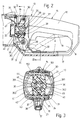
- FIGS. 2 and 3 Details of the fixing devices 20 and the rotatable mounting of the handle 15 on the motor housing 11 are shown in FIGS. 2 and 3.
- the bearing journal 21 with journal section 22, like the motor housing 11, is made of plastic and is integrally formed on it during the injection molding process.
- a turnstile 24 with an annular collar 25 is rotatably and axially immovably received on the journal section 22 of the journal 21.
- the annular collar 25 is supported axially via a sliding washer 26 on the annular shoulder 23 of the journal 21 and is held axially immovably by a clamping plate 27.
- the clamping plate 27 is by means of screws 28 on the free end face of the pin section 22 screwed on, a disc spring 29 being inserted between the clamping plate 27 and the end face of the collar 25 on the turnstile 24.
- the turnstile 25 is made of plastic and is screwed to the handle 15, which consists of two housing shells 151 and 152, by means of two screws 30, 31, which at the same time hold the two housing shells 151, 152 together.
- the two housing shells 151, 152 engage with a radial projection 32 in a circumferential groove 33 formed on the motor housing 11.
- the fixing device 20 has three pairs of ribs 34, 35, 36 formed on the motor housing and each offset by an angle of rotation of 90 °, the ribs of which are arranged at a parallel distance from one another and run radially.
- the ribs 351, 352 and 361, 362 of the pair of ribs 35, 36 can be seen in FIG. 3 and only the ribs 341 of the pair of ribs 34 can be seen in FIG.
- the fixing device 20 includes a locking cam 37 pivotally held on the turnstile 24, the axial width of which corresponds to the clear distance between the ribs of the pairs of ribs 34-36, so that it can be pivoted in with lateral positive locking between the pairs of ribs 34-36.
- the locking cam 37 is connected in one piece to a manually pivotable locking lever 38 which projects through a recess 39 in the two housing shells 151, 152 and into the passage opening 18 of the handle 15.
- the locking lever 38 is approximately U-shaped in cross-section, and shaped so that in its locking position, in which the locking cam 37 positively engages between the ribs of one of the pairs of ribs 34 - 36, the bracket 17 from its side facing the switch strip 19 spreads.
- the locking lever 38 is pivoted in the direction of the arrow in FIGS. 1 and 2 and protrudes into the through opening 18 in the handle 15 (dashed line illustration of the locking lever 38 in FIG. 2).
- a ring segment 40 or 41 which extends coaxially to the turnstile 24 in the direction of rotation of the turnstile 24, is arranged such that the locking cam 37 pivoted out of its locking position when the handle 15 or the motor housing 11 is turned at a short distance slides along these ring segments 40, 41 and cannot be pivoted back. This prevents the locking lever 38 from being pivoted onto the bracket 17 of the handle 15 outside of the predetermined locking positions and thus preventing the locking cam 37 from rotating in front of the ribs of the pairs of ribs 34-36.
- a radially projecting stop cam 42 (FIG. 3) is arranged on the bearing journal 21 and an annular recess 43 extending over 180 ° is provided in FIG which of the stop cams 42 protrude.
- the annular recess 43 has such an arrangement that when one of the two radial boundary surfaces 44 or 45 of the recess 43 stops on the stop cam 42, the locking cam 37 pivotally held on the turnstile 24 is automatically aligned with one of the pairs of ribs 35, 36 on the motor housing 11.
- the pairs of ribs 34 - 36 also serve to support the central bearing pin 21 on the motor housing 11.
- the bearing pin 21 has an axial opening 46, through which the electrical connecting cable 47 is passed from the on and off switch actuated by the switch strip 19 to the drive motor.
Landscapes
- Engineering & Computer Science (AREA)
- Mechanical Engineering (AREA)
- Finish Polishing, Edge Sharpening, And Grinding By Specific Grinding Devices (AREA)
- Milling, Drilling, And Turning Of Wood (AREA)
- Dovetailed Work, And Nailing Machines And Stapling Machines For Wood (AREA)
Abstract
Description
- Die Erfindung geht aus von einer Handwerkzeugmaschine, insbesondere einer handgeführten Winkelschleifmaschine, der im Oberbegriff des Anspruchs 1 definierten Gattung.
- Handwerkzeugmaschinen, insbesondere handgeführte Winkelschleifmaschinen, sind heute ausschließlich mit einem Ein- und Ausschalter für den elektrischen Antrieb ausgerüstet, der über die Schalterleiste betätigt wird. Die Schalterleiste liegt an der Handgriffunterseite und wird beim Umfassen des Handgriffes von mindestens einem Finger betätigt und während des Arbeitens mit der Maschine betätigt gehalten. Die ergonomische Gestaltung des Handgriffes, wie Querschnittsform und Neigungswinkel zur Geräteachse, ist für eine einzige Arbeitsstellung der Maschine optimiert.
- Einige Handwerkzeugmaschinen werden in mehr als einer Arbeitsstellung für verschiedene Arbeitsgänge verwendet. Eine Winkelschleifmaschine z.B. wird neben dem Schleifen oder Schrubben auch für Trennarbeiten, z.B. zum Trennen von Steinplatten, verwendet. Die vorstehend angesprochene optimale Arbeitsstellung ist üblicherweise für die Arbeitsstellung Schrubben gegeben, in welcher die Schleifscheibe nach unten weist, also in etwa parallel zur Schalterleiste liegt. Bei Trennarbeiten hingegen wird die Winkelschleifmaschine um 90° um ihre Längsachse nach links oder rechts gedreht, so daß die Trennscheibe etwa senkrecht zum Werkstück steht. Durch diese Drehung kommt der Handgriff zusammen mit der Schalterleiste in eine ungünstige Lage zur umfassenden Hand. Wird die Maschine nach links gedreht und der Handgriff mit der rechten Hand umfaßt, kommt die Schalterleiste im Handballen zu liegen. Wird die Maschine nach rechts gedreht und mit der rechten Hand gehalten, kann die Schalterleiste nur noch mit dem Daumen betätigt und gehalten werden. In beiden Fällen ist ein sicheres und ermüdungsfreies Halten der Schalterleiste nicht möglich. Außerdem kann im Gefahrensfall im Hinblick auf die Lage von Einschaltsperre und Einschaltverriegelung nicht schnell genug reagiert und abgeschaltet werden.
- Um diesen Nachteil zu umgehen, ist bereits bei einer Handwerkzeugmaschine der eingangs genannten Art der Gehäuseteil Handgriff oder der Gehäuseteil Getriebekopf am Motorgehäuse drehbar gehalten und kann in definierten Drehstellungen für eine jeweils ergonomisch günstige Arbeitshaltung mittels einer Fixiervorrichtung festgelegt werden.
- Bei einer bereits vorgeschlagenen Handwerkzeugmaschine dieser Art (EP-A-00539382 gemäß Art. 54 (3) EPÜ) wird die Drehbarkeit des Handgriffs bzw. des Getriebekopfs dadurch erreicht, daß das schalenförmige Gehäuse des drehbaren Gehäuseteils mit einem radial vorspringenden Bund versehen ist, der in eine Umlaufnut am Motorgehäuse eingreift. Die manuell betätigbare Fixiervorrichtung weist eine Verriegelungsvorrichtung zur Verriegelung des drehbaren Gehäuseteils am Motorgehäuse und eine Klemmvorrichtung zum Verspannen des drehbaren Gehäuseteils am Motorgehäuse auf. Die Verriegelungsvorrichtung weist dabei mindestens zwei im Motorgehäuse um einen Drehwinkel zueinander versetzt angeordnete Verriegelungsnuten und einen im Schalengehäuse des drehbaren Gehäuseteils schwenkbaren Verriegelungsnocken auf, der formschlüssig in jeweils eine der Verriegelungsnuten einzugreifen vermag. Die Klemmvorrichtung weist eine quer zu einem Längsschlitz im vorspringenden Bund des Schalengehäuses sich erstreckende Spannschraube auf, die mittels eines Spannhebels in einem Gewinde verschraubbar ist und die die beidseitig des Längsschlitzes ausgebildeten Gehäusebereiche des Schalengehäuses unter Reduzierung der Breite des Längsschlitzes aufeinanderzu zu bewegen vermag. Die zur Verriegelungsvorrichtung zusätzliche Klemmvorrichtung ist deshalb erforderlich, damit einerseits eine leichte Drehbeweglichkeit des drehbaren Gehäuseteils am Motorgehäuse sichergestellt ist und andererseits bei Arbeiten mit der Handwerkzeugmaschine in den unterschiedlichen Relativstellungen von Motorgehäuse und drehbarem Gehäuseteil immer eine steife Verbindung dieser Gehäuseteile gegeben ist.
- Die erfindungsgemäße Handwerkzeugmaschine mit den kennzeichnenden Merkmalen des Anspruchs 1 hat demgegenüber den Vorteil, daß eine gute Drehführung des drehabren Gehäuseteils am Motorgehäuse erreicht wird, die einerseits leichtgängig und andererseits eine Relativbeweglichkeit von Maschinengehäuse und drehbarem Gehäuseteil in Längsrichtung zueinander sicher ausschließt. Damit kann auf eine zur Verriegelungsvorrichtung zusätzliche Klemmvorrichtung verzichtet werden. Trotz leichtgängiger Drehbeweglichkeit des drehbaren Gehäuseteils ist in jeder Verriegelungsstellung ein formsteifes Maschinengehäuse gegeben, das gut zu hantieren ist. Durch den Wegfall der Klemmvorrichtung wird die Handwerkzeugmaschine konstruktiv einfacher, was sich in den geringeren Herstellungskosten niederschlägt.
- Durch die in den weiteren Ansprüchen aufgeführten Maßnahmen sind vorteilhafte Weiterbildungen und Verbesserungen der im Anspruch 1 angegebenen Handwerkzeugmaschine möglich.
- Gemäß einer bevorzugten Ausführungsform der Erfindung weist die Fixiervorrichtung mindestens zwei am Motorgehäuse ausgebildete, um einen vorgegebenen Drehwinkel zueinander versetzt angeordnete Rippenpaare, deren radial sich erstreckende Rippen jeweils im Parallelabstand voneinander angeordnet sind, und einen am Drehkreuz schwenkbar gehaltenen Verriegelungsnocken auf, der zwischen jeweils einem Rippenpaar mit seitlichem Formschluß einzugreifen vermag. Der Verriegelungsnocken ist mit einem manuell schwenkbaren Sperrhebel starr verbunden, der aus dem drehbaren Gehäuseteil vorsteht.
- Bei Handwerkzeugmaschinen, bei welchen der drehbare Gehäuseteil von dem Handgriff gebildet ist, der einen die Schalterleiste mit Abstand überziehenden Bügel aufweist, ist vorteilhaft der Sperrhebel im Querschnitt etwa U-förmig ausgebildet und so geformt, daß er in seiner Verriegelungsstellung den Bügel am Handgriff von dessen der Schalterleiste zugekehrten Seite her übergreift. Beim Lösen der Fixiervorrichtung schwenkt dann dieser Sperrhebel in Richtung auf die Schalterleiste und blockiert die zwischen Schalterleiste und Bügel befindlichen Durchgrifföffnung für die Griffhand des Benutzers, so daß dieser automatisch auf die nicht verriegelte Fixiervorrichtung aufmerksam gemacht wird.
- Die Erfindung ist anhand eines in der Zeichnung dargestellten Ausführungsbeispiels in der nachfolgenden Beschreibung näher erläutert. Es zeigen:
- Fig. 1
- eine Seitenansicht einer handgeführten elektrischen Winkelschleifmaschine,
- Fig. 2
- eine vergrößerte Darstellung des Handgriffs mit Teilen des Motorgehäuses der Winkelschleifmaschine in Fig. 1, teilweise geschnitten,
- Fig. 3
- einen Schnitt längs der Linie II-II in Fig. 2.
- Die in Fig. 1 in Seitenansicht zu sehende handgeführte elektrische Winkelschleifmaschine als Ausführungsbeispiel für eine allgemeine elektrische Handwerkzeugmaschine weist ein Maschinengehäuse 10 auf, das in ein Motorgehäuse 11, in einen an der einen Gehäusestirnseite des Motorgehäuses 11 angeordneten Getriebekopf 12 mit vorstehender Antriebsspindel 13 für eine Schleifscheibe 14 und in einen an der anderen Gehäusestirnseite des Motorgehäuses 11 angeordneten Handgriff 15 unterteilt ist, der am Motorgehäuse 11 um dessen Längsachse über einen vorgegebenen Drehbereich drehbar ausgebildet ist. Der Handgriff 15 besteht aus einem Stielgriff 16, der beim Arbeiten mit der Winkelschleifmaschine von der Hand umschlossen wird, und aus einem daran einstückig angesetzten Bügel 17, der auf der Unterseite den Stielgriff 16 unter Belassung einer Durchgrifföffnung 18 überzieht und beim Arbeiten mit der Winkelschleifmaschine die um den Stielgriff 16 gelegten Finger nach unten schützend abdeckt. An der dem Bügel 17 zugekehrten Unterseite des Stielgriffs 16 ragt eine. Schalterleiste 19 in die Durchgriffsöffnung 18 hinein, die einen Ein- und Ausschalter für einen elektrischen Antriebsmotor betätigt, der im Motorgehäuse 11 untergebracht ist. Der Getriebekopf 12 ist fest mit dem Motorgehäuse 11 verbunden, während der am Motorgehäuse 11 drehbare Handgriff 15 mittels einer Fixiervorrichtung 20 am Motorgehäuse 11 in drei unterschiedlichen Drehstellungen festgelegt werden kann. In der in Fig. 1 dargestellten Relativlage von Motorgehäuse 11 und Handgriff 15 zueinander wird die Winkelschleifmaschine zum sog. Schrubben verwendet. In dieser Relativlage liegt die Schleifscheibe 14 in etwa parallel zur Schalterleiste 19. Aus dieser Schrubbstellung kann durch Drehen des Handgriffes 15 bzw. des Motorgehäuses 11 um 90° nach links oder rechts die Winkelschleifmaschine für den Arbeitsgang "Trennen" vorbereitet werden. Bei dieser Arbeitstellung der Winkelschleifmaschine behält in Fig. 1 der Handgriff 15 seine Lage bei und das Motorgehäuse 11 samt Getriebekopf 12 ist um 90° verdreht, so daß die Schleifscheibe 14 die in Fig. 1 strichliniert eingezeichnete Lage einnimmt, bei welcher sie etwa rechtwinklig zur Schalterleiste 19 ausgerichtet ist.
- Einzelheiten der Fixiervorrichtungen 20 sowie der drehbeweglichen Halterung des Handgriffs 15 am Motorgehäue 11 sind in Fig. 2 und 3 dargestellt. An dem Motorgehäuse 11 ist ein zentraler Lagerzapfen 21 angespritzt, an dem ein Zapfenabschnitt 22 zum freien Ende im Durchmesser reduziert ist, wobei am Übergang vom Lagerzapfen 21 zum Zapfenabschnitt 22 eine Ringschulter 23 ausgebildet ist. Der Lagerzapfen 21 mit Zapfenabschnitt 22 besteht wie das Motorgehäuse 11 aus Kunststoff und ist an diesem beim Spritzvorgang gleich mit angeformt. Auf dem Zapfenabschnitt 22 des Lagerzapfens 21 ist ein Drehkreuz 24 mit einem Ringbund 25 drehbar und axial unverschiebbar aufgenommen. Der Ringbund 25 stützt sich dabei axial über eine Gleitscheibe 26 an der Ringschulter 23 des Lagerzapfens 21 ab und wird von einem Spannteller 27 axial unverschieblich gehalten. Der Spannteller 27 ist mittels Schrauben 28 auf die freie Stirnseite des Zapfenabschnitts 22 aufgeschraubt, wobei zwischen Spannteller 27 und Stirnseite des Ringbundes 25 am Drehkreuz 24 eine Tellerfeder 29 eingelegt ist. Das Drehkreuz 25 ist aus Kunststoff gefertigt und an dem aus zwei Gehäuseschalen 151 und 152 bestehenden Handgriff 15 mittels zweier Schrauben 30,31, die zugleich die beiden Gehäuseschalen 151,152 Zusammenhalten, angeschraubt. Zur staubdichten Abdeckung greifen die beiden Gehäuseschalen 151,152 mit einem radialen Vorsprung 32 in eine am Motorgehäuse 11 ausgebildete Umlaufnut 33 ein.
- Die Fixiervorrichtung 20 weist drei am Motorgehäuse ausgeformte, jeweils um einen Drehwinkel von 90° zueinander versetzte Rippenpaare 34,35,36 auf, deren Rippen im Parallelabstand voneinander angeordnet sind und radial verlaufen. In Fig. 3 sind die Rippen 351,352 und 361,362 der Rippenpaare 35,36 und in Fig. 2 nur die Rippen 341 des Rippenpaares 34 zu sehen. Ferner gehört zur Fixiervorrichtung 20 ein am Drehkreuz 24 schwenkbar gehaltener Verriegelungsnocken 37, dessen axiale Breite dem lichten Abstand zwischen den Rippen der Rippenpaare 34 - 36 entspricht, so daß er mit seitlichem Formschluß zwischen die Rippenpaare 34 - 36 eingeschwenkt werden kann. Der Verriegelungsnocken 37 ist einstückig mit einem manuell schwenkbaren Sperrhebel 38 verbunden, der durch eine Aussparung 39 in den beiden Gehäuseschalen 151,152 hindurch und in die Durchgrifföffnung 18 des Handgriffs 15 hineinragt. Der Sperrhebel 38 ist im Querschnitt etwa U-förmig ausgebildet, und so geformt, daß er in seiner Verriegelungsstellung, in welcher der Verriegelungsnocken 37 zwischen die Rippen eines der Rippenpaare 34 - 36 formschlüssig eingreift, den Bügel 17 von dessen der Schalterleiste 19 zugekehrten Seite her übergreift. Beim Lösen der Fixiervorrichtung 20 wird der Sperrhebel 38 in Pfeilrichtung in Fig. 1 und 2 geschwenkt und ragt in die Durchgrifföffnung 18 im Handgriff 15 hinein (strichlinierte Darstellung des Sperrhebels 38 in Fig. 2). Damit ist die Durchgrifföffnung 18 für das Durchgreifen mit der Griffhand blockiert, und der Benutzer wird auf die entriegelte Fixiervorrichtung (20) automatisch aufmerksam gemacht. Zwischen den Rippenpaaren 34,35,36 ist jeweils ein in Drehrichtung des Drehkreuzes 24 koaxial zu diesem verlaufendes Ringsegment 40 bzw. 41 so angeordnet, daß der aus seiner Verriegelungsstellung ausgeschwenkte Verriegelungsnocken 37 beim Drehen des Handgriffs 15 bzw. des Motorgehäuses 11 mit geringem Abstand an diesen Ringsegmenten 40,41 entlanggleitet und nicht zurückgeschwenkt werden kann. Damit wird verhindert, daß der Sperrhebel 38 außerhalb der vorbestimmten Verriegelungsstellungen auf den Bügel 17 des Handgriffs 15 aufgeschwenkt werden kann und damit ein Drehen des Verriegelungsnockens 37 vor die Rippen der Rippenpaare 34 - 36 blockiert ist.
- Zur Begrenzung der Drehbeweglichkeit des Handgriffs 15 und zur gleichzeitigen automatischen Einstellung der 90° Drehstellungen des Handgriffs 15 ist am Lagerzapfen 21 ein radial wegstehender Anschlagnocken 42 (Fig. 3) angeordnet und im Ringbund 25 eine über 180° sich erstreckende ringförmige Ausnehmung 43 vorgesehen, in welche der Anschlagnocken 42 hineinragt. Die ringförmige Ausnehmung 43 hat dabei eine solche Anordnung, daß beim Anschlag einer der beiden radialen Begrenzungsflächen 44 bzw. 45 der Ausnehmung 43 an dem Anschlagnocken 42 der am Drehkreuz 24 schwenkbeweglich gehaltene Verriegelungnocken 37 automatisch mit einem der Rippenpaare 35,36 am Motorgehäuse 11 fluchtet. Die Rippenpaare 34 - 36 dienen zugleich der Abstützung des zentralen Lagerzapfens 21 am Motorgehäuse 11. Der Lagerzapfen 21 weist einen axialen Durchbruch 46 auf, durch welche das elektrische Verbindungskabel 47 von dem von der Schalterleiste 19 betätigten Ein- und Ausschalter zum Antriebsmotor hindurchgeführt ist.
Claims (7)
- Handwerkzeugmaschine, insbesondere handgeführte Winkelschleifmaschine, mit einem Maschinengehäuse (10), das in ein einen elektrischen Antrieb aufnehmendes Motorgehäuse (11), in einen an der einen Stirnseite des Motorgehäuses (11) angeordneten Getriebekopf (12) mit vorstehender Antriebsspindel (13) für ein Werkzeug und in einen an der anderen Stirnseite des Motorgehäuses (11) angeordneten Handgriff (15) mit einer Schalterleiste (19) zum Ein- und Ausschalten des elektrischen Antriebs unterteilt ist, wobei entweder der Handgriff (15) oder der Getriebekopf (12) als drehbarer Gehäuseteil relativ zum Motorgehäuse (11) um dessen Längsachse drehbar ausgebildet ist, und mit einer manuell betätigbaren Fixiervorrichtung (20) zum Festsetzen des drehbaren Gehäuseteils in mindestens zwei unterschiedlichen Drehstellungen, wobei am Motorgehäuse (10) ein zentraler Lagerzapfen (21) ausgeformt ist, auf dem ein Drehkreuz (24) axial unverschieblich und drehbar aufgenommen ist, das Drehkreuz (24) mit dem drehbaren Gehäuseteil (15) fest verbunden ist und die Fixiervorrichtung (20) eine formschlüssige Verriegelung zwischen Motorgehäuse (11) und Drehkreuz (24) bewirkt.
- Maschine nach Anspruch 1, dadurch gekennzeichnet, daß die Fixiervorrichtung (20) mindestens zwei am Motorgehäuse (10) ausgeformte, um einen vorbestimmten Drehwinkel zueinander versetzter Rippenpaare (34,35,36), deren Rippen (341,351,352,361,362) im Parallelabstand voneinander angeordnet sind und radial verlaufen, und einen am Drehkreuz (24) schwenkbar gehaltenen Verriegelungsnocken (37) aufweist, der zwischen jeweils den Rippen (341,351,352,361,362) eines jeden Rippenpaares (34,35,36) mit seitlichem Formschluß einzugreifen vermag und mit einem aus dem drehbaren Gehäuseteil (15) vorstehenden, manuell betätigbaren Sperrhebel (38) starr verbunden ist.
- Maschine nach Anspruch 2, dadurch gekennzeichnet, daß zwischen den mindestens zwei Rippenpaaren (34,35,36) ein in Drehrichtung des Drehkranzes (24) verlaufendes Ringsegment (40,41) so angeordnet ist, daß der aus seiner Verriegelungsstellung ausgeschwenkte Verriegelungsnocken (37) beim Drehen des drehbaren Gehäuseteils (15) mit geringem Abstand an dem Ringsegment (40,41) entlanggleitet und an einer Rückschwenkbewegung gehindert ist.
- Maschine nach Anspruch 2 oder 3, dadurch gekennzeichnet, daß der drehbare Gehäuseteil der Handgriff (15) ist, der einen die Schalterleiste (19) mit Abstand überziehenden Bügel (17) aufweist, und daß der Sperrhebel (38) im Querschnitt etwa U-förmig ausgebildet und so geformt ist, daß er in seiner Verriegelungsstellung den Bügel (17) von dessen der Schalterleiste (19) zugekehrten Seite her übergreift.
- Maschine nach einem der Ansprüche 1 - 4, dadurch gekennzeichnet, daß das Drehkreuz (24) auf dem Lagerzapfen (21,22) mit einem Ringbund (25) sitzt, der sich über eine Gleitscheibe (26) an einer Ringschulter (23) des Lagerzapfens (22) axial abstützt, daß auf der freien Stirnseite des Lagerzapfens (21) ein Spannteller (27) befestigt ist und daß eine Tellerfeder (29) sich zwischen Spannteller (27) und Ringbund (25) des Drehkreuzes (24) abstützt.
- Maschine nach einem der Ansprüche 1 - 5, dadurch gekennzeichnet, daß am Lagerzapfen (21) ein radial wegstehender Anschlagnocken (42) angeordnet ist und daß der Ringbund (25) eine ringförmige Ausnehmung (43) aufweist, in welche der Anschlagnocken (42) hineinragt und die eine solche Länge und Anordnung hat, daß beim Anschlag einer der beiden radialen Begrenzungsflächen (44,45) der Ausnehmung (43) an dem Anschlagnocken (42) der am Drehkreuz (24) schwenkbar gehaltene Verriegelungsnocken (37) mit einem der Rippenpaare (35,36) am Motorgehäuse (11) zum Einschwenken zwischen dessen Rippen (351,352,361,362) fluchtet.
- Maschine nach einem der Ansprüche 1 - 6, dadurch gekennzeichnet, daß der Lagerzapfen (21) einen axialen Durchbruch (46) zum Durchführen eines Anschlußkabels (47) für die Schalterleiste (19) aufweist.
Applications Claiming Priority (3)
| Application Number | Priority Date | Filing Date | Title |
|---|---|---|---|
| DE4102838 | 1991-01-31 | ||
| DE4102838A DE4102838A1 (de) | 1991-01-31 | 1991-01-31 | Handwerkzeugmaschine |
| PCT/DE1991/000988 WO1992013678A1 (de) | 1991-01-31 | 1991-12-18 | Handwerkzeugmaschine |
Publications (2)
| Publication Number | Publication Date |
|---|---|
| EP0569370A1 EP0569370A1 (de) | 1993-11-18 |
| EP0569370B1 true EP0569370B1 (de) | 1994-09-21 |
Family
ID=6424066
Family Applications (1)
| Application Number | Title | Priority Date | Filing Date |
|---|---|---|---|
| EP92901069A Expired - Lifetime EP0569370B1 (de) | 1991-01-31 | 1991-12-18 | Handwerkzeugmaschine |
Country Status (5)
| Country | Link |
|---|---|
| US (1) | US5466183A (de) |
| EP (1) | EP0569370B1 (de) |
| JP (1) | JP3032010B2 (de) |
| DE (2) | DE4102838A1 (de) |
| WO (1) | WO1992013678A1 (de) |
Families Citing this family (67)
| Publication number | Priority date | Publication date | Assignee | Title |
|---|---|---|---|---|
| DE4332986C2 (de) * | 1993-09-28 | 1999-03-11 | Fraunhofer Ges Forschung | Handgriff für motorgetriebene Arbeitsgeräte mit verstellbarem Bedienelement |
| JP3189577B2 (ja) * | 1993-10-29 | 2001-07-16 | 日立工機株式会社 | 電動石材カッタ |
| USD375439S (en) | 1994-12-27 | 1996-11-12 | Makita Corporation | Cordless circular saw |
| US5687802A (en) * | 1995-09-21 | 1997-11-18 | Chicago Pneumatic Tool Company | Power hand tool with rotatable handle |
| USD385764S (en) * | 1995-09-28 | 1997-11-04 | Tadao Goto | Portable air grinder |
| US6280309B1 (en) * | 1995-10-19 | 2001-08-28 | Norton Company | Accessories and attachments for angle grinder |
| USD380069S (en) * | 1995-10-23 | 1997-06-17 | Waxing Corporation Of America, Inc. | Detailing polisher |
| USD392529S (en) | 1995-11-08 | 1998-03-24 | Tadao Goto | Portable air grinder |
| DE19546328B4 (de) * | 1995-12-12 | 2007-12-13 | Robert Bosch Gmbh | Handwerkzeugmaschine mit einem drehbaren Handgriff |
| DE19549840B4 (de) * | 1995-12-12 | 2015-08-06 | Robert Bosch Gmbh | Handwerkzeugmaschine |
| DE19606535C2 (de) * | 1996-02-22 | 1999-01-07 | Metabowerke Kg | Motorbetriebenes Handwerkzeug mit abnehmbarem Handgriff |
| USD390081S (en) | 1997-01-21 | 1998-02-03 | Black & Decker Inc. | Circular saw |
| JP3822333B2 (ja) * | 1997-05-14 | 2006-09-20 | 株式会社共立 | 動力作業機用ハンドル装置 |
| US6026910A (en) * | 1998-01-13 | 2000-02-22 | Chicago Pneumatic Tool Company | Power tool and vibration isolator therefor |
| US6527060B1 (en) * | 1998-02-03 | 2003-03-04 | Atlas Copco Tools Ab | Portable power tool with separate pistol-type handle |
| US6176864B1 (en) * | 1998-03-09 | 2001-01-23 | Corvascular, Inc. | Anastomosis device and method |
| US6108916A (en) | 1998-08-14 | 2000-08-29 | Milwaukee Electric Tool Corporation | Movable handle for a power tool |
| EP1016505B1 (de) * | 1998-12-31 | 2005-01-19 | C. & E. Fein GmbH | Elektrowerkzeug, insbesondere Winkelschleifer |
| ATE287319T1 (de) * | 1998-12-31 | 2005-02-15 | Fein C & E Gmbh | Elektrowerkzeug, insbesondere winkelschleifer |
| DE19938176A1 (de) * | 1999-08-16 | 2001-03-08 | Bosch Gmbh Robert | Handwerkzeugmaschine |
| US6499172B1 (en) | 1999-09-15 | 2002-12-31 | Wmh Tool Group, Inc. | Power tool adjustable handle assembly |
| DE10005989A1 (de) * | 2000-02-10 | 2001-08-16 | Bosch Gmbh Robert | Handwerkzeugmaschine |
| US6443675B1 (en) * | 2000-02-17 | 2002-09-03 | Roto Zip Tool Corporation | Hand-held power tool |
| USD456685S1 (en) | 2000-06-30 | 2002-05-07 | Porter-Cable Corporation | Knurled collar guard |
| USD456234S1 (en) | 2000-06-30 | 2002-04-30 | Porter-Cable Corporation | Knurled collar attachment system |
| USD458825S1 (en) | 2000-06-30 | 2002-06-18 | Porter-Cable Corporation | Tuck-pointing system |
| US6464573B1 (en) | 2000-06-30 | 2002-10-15 | Porter-Cable Corporation | Guard attachment system with knurled clamp ring |
| US6502647B1 (en) | 2000-10-16 | 2003-01-07 | Douglas C. Krzyzewski | Pneumatic tool assembly |
| TW496238U (en) * | 2000-12-26 | 2002-07-21 | Mobiletron Electronics Co Ltd | Safety structure for replacing of grinding wheel for grinder |
| JP3955745B2 (ja) * | 2001-06-27 | 2007-08-08 | 株式会社マキタ | アングルドリル |
| US6912790B2 (en) | 2001-12-03 | 2005-07-05 | Milwaukee Electric Tool Corporation | Handle arrangement for a reciprocating saw |
| US6671969B2 (en) | 2001-12-18 | 2004-01-06 | Porter-Cable/Delta | Adjustable shoe for a reciprocating saw |
| EP1327497B1 (de) * | 2002-01-10 | 2006-05-31 | Black & Decker Inc. | Getriebegehäuse |
| DE10248866B4 (de) | 2002-10-18 | 2016-03-17 | Robert Bosch Gmbh | Handwerkzeugmaschine |
| US7854054B2 (en) * | 2003-01-08 | 2010-12-21 | Robert Bosch Tool Corporation | Attachment for power tool |
| CA2454900C (en) * | 2003-01-08 | 2011-12-13 | Credo Technology Corporation | Attachment for power tool |
| US7108593B2 (en) * | 2003-11-03 | 2006-09-19 | Wmh Tool Group, Inc. | Power tool adjustable handle assembly |
| JP4421923B2 (ja) * | 2004-03-22 | 2010-02-24 | 本田技研工業株式会社 | 動力作業機 |
| DE102004036420A1 (de) * | 2004-07-27 | 2006-03-23 | Hilti Ag | Werkzeuggerätehandgriff |
| DE202005004316U1 (de) * | 2005-03-17 | 2006-07-27 | Dolmar Gmbh | Arbeitsgerät |
| EP1940594B1 (de) * | 2005-10-29 | 2009-07-08 | AEG Electric Tools GmbH | Handwerkzeugmaschine |
| US7222679B1 (en) * | 2006-03-17 | 2007-05-29 | Snap-On Incorporated | Random orbital sander |
| USD564321S1 (en) | 2006-04-12 | 2008-03-18 | Professional Tool Products, Llc | Portion of a housing for a rotary tool |
| AU2008246247B2 (en) * | 2006-04-26 | 2011-11-03 | Demain Technology Pty Ltd | A handle assembly for a power tool |
| JP2009534203A (ja) * | 2006-04-26 | 2009-09-24 | ディメイン テクノロジー プロプライエタリー リミテッド | 電動工具用の取っ手組立部品 |
| US8061043B2 (en) | 2006-11-15 | 2011-11-22 | Milwaukee Electric Tool Corporation | Power tool |
| DE102007057454A1 (de) * | 2007-11-29 | 2009-06-04 | Robert Bosch Gmbh | Handwerkzeugmaschine mit in einem Gehäuse verlaufenden Kabeln |
| US8407902B2 (en) * | 2008-03-07 | 2013-04-02 | Milwaukee Electric Tool Corporation | Reciprocating power tool having a counterbalance device |
| WO2009111747A2 (en) | 2008-03-07 | 2009-09-11 | Milwaukee Electric Tool Corporation | Portable battery-powered reciprocating saw |
| DE102008001252A1 (de) * | 2008-04-18 | 2009-10-22 | Robert Bosch Gmbh | Werkzeugmaschine, insbesondere Handwerkzeugmaschine |
| US8690497B2 (en) * | 2008-10-30 | 2014-04-08 | Black & Decker Inc. | Handle and attachments for right angle drill |
| US8156656B2 (en) * | 2009-05-07 | 2012-04-17 | Black & Decker Inc. | Hedgetrimmer with rotatable rear handle |
| USD623909S1 (en) | 2009-10-30 | 2010-09-21 | Black & Decker Inc. | Hedgetrimmer with rotating handle |
| CN103415374B (zh) * | 2011-03-21 | 2015-08-19 | 创科电动工具科技有限公司 | 具有锁定的可旋转手柄的手持式电动工具 |
| USD648999S1 (en) * | 2011-05-11 | 2011-11-22 | Robert Bosch Gmbh | Saw |
| US8872049B2 (en) | 2012-04-18 | 2014-10-28 | Milwaukee Electric Tool Corporation | Trigger lock-on lock-off mechanism |
| USD694606S1 (en) | 2012-08-22 | 2013-12-03 | Robert Bosch Gmbh | Right angle attachment for a rotary hand tool |
| DE102012025309A1 (de) * | 2012-12-22 | 2014-06-26 | Andreas Stihl Ag & Co. Kg | Handgeführtes Arbeitsgerät mit einem Antriebsmotor zum Antrieb mindestens eines Werkzeugs und Verfahren zu dessen Betrieb |
| DE102013202953A1 (de) * | 2013-02-22 | 2014-09-11 | Robert Bosch Gmbh | Handwerkzeugmaschine |
| JP6727828B2 (ja) * | 2016-02-05 | 2020-07-22 | 株式会社マキタ | 動力工具 |
| CN105729280A (zh) * | 2016-03-08 | 2016-07-06 | 吴刚 | 装修板材抛光装置及其使用方法 |
| CN111250782A (zh) * | 2018-11-30 | 2020-06-09 | 宝时得科技(中国)有限公司 | 便携式切割机 |
| CN110014299A (zh) * | 2019-02-20 | 2019-07-16 | 温州金石机器人科技有限公司 | 磨抛、去毛刺智能流水线 |
| CN112454100B (zh) * | 2019-09-09 | 2024-10-11 | 宝时得机械(张家港)有限公司 | 电动工具 |
| CN115723013A (zh) * | 2021-09-01 | 2023-03-03 | 株式会社牧田 | 研磨工具 |
| USD1054820S1 (en) | 2022-03-11 | 2024-12-24 | Wen Yi | Attachment for grinding tool |
| EP4302909A3 (de) * | 2022-06-13 | 2024-03-13 | Milwaukee Electric Tool Corporation | Trennsäge mit spritzschutz |
Family Cites Families (7)
| Publication number | Priority date | Publication date | Assignee | Title |
|---|---|---|---|---|
| DE1068145B (de) * | 1959-10-29 | Robert Bosch G.M.B.H., Stuttgart | Handschleifmaschine mit einer aufklappbaren Schutzhaube | |
| US1702742A (en) * | 1925-06-10 | 1929-02-19 | Millers Falls Co | Electric tool |
| DE6753525U (de) * | 1968-08-22 | 1969-05-14 | Bosch Gmbh Robert | Kraftwerkzeug |
| DE2335867A1 (de) * | 1973-07-14 | 1975-01-30 | Metabowerke Kg | Motorisch angetriebenes handwerkzeug mit schalldaemmendem gehaeuse |
| DE9018178U1 (de) * | 1989-09-08 | 1998-04-09 | Fa. Andreas Stihl, 71336 Waiblingen | Handgeführtes Arbeitsgerät |
| DE4022668A1 (de) * | 1990-07-17 | 1992-01-23 | Bosch Gmbh Robert | Elektrische handwerkzeugmaschine, insbesondere winkelschleifmaschine |
| JPH04223861A (ja) | 1990-12-20 | 1992-08-13 | Makita Corp | 携帯用回転工具 |
-
1991
- 1991-01-31 DE DE4102838A patent/DE4102838A1/de not_active Withdrawn
- 1991-12-18 WO PCT/DE1991/000988 patent/WO1992013678A1/de not_active Ceased
- 1991-12-18 DE DE59103068T patent/DE59103068D1/de not_active Expired - Lifetime
- 1991-12-18 EP EP92901069A patent/EP0569370B1/de not_active Expired - Lifetime
- 1991-12-18 US US08/094,149 patent/US5466183A/en not_active Expired - Lifetime
- 1991-12-18 JP JP4501126A patent/JP3032010B2/ja not_active Expired - Fee Related
Also Published As
| Publication number | Publication date |
|---|---|
| JPH06504490A (ja) | 1994-05-26 |
| WO1992013678A1 (de) | 1992-08-20 |
| EP0569370A1 (de) | 1993-11-18 |
| JP3032010B2 (ja) | 2000-04-10 |
| US5466183A (en) | 1995-11-14 |
| DE59103068D1 (de) | 1994-10-27 |
| DE4102838A1 (de) | 1992-08-06 |
Similar Documents
| Publication | Publication Date | Title |
|---|---|---|
| WO1992013678A1 (de) | Handwerkzeugmaschine | |
| DE19546328B4 (de) | Handwerkzeugmaschine mit einem drehbaren Handgriff | |
| EP0569382B1 (de) | Handwerkzeugmaschine | |
| EP0539382B1 (de) | Elektrische handwerkzeugmaschine, insbesonder winkelschleifmaschine | |
| EP0566580B1 (de) | Elektrische handdrehwerkzeugmaschine, insbesondere handkreissäge | |
| EP0005540B1 (de) | Fadenschneider zum Beschneiden von Rasenkanten | |
| DE102008002548B4 (de) | Werkzeugmaschine, insbesondere Handwerkzeugmaschine | |
| DE102017108209B4 (de) | Schutzabdeckung für ein schleifgerät | |
| DE4432973B4 (de) | Elektrische Handwerkzeugmaschine mit einer Spindelarretierung | |
| DE19617572A1 (de) | Elektrische Handschleifmaschine | |
| EP0583270A1 (de) | Handwerkzeugmaschine. | |
| EP1368156B1 (de) | Handwerkzeugmaschine mit einer schwenkbaren werkzeugabdeckung | |
| EP1193036B1 (de) | Handwerkzeugmaschine mit Werkzeugwelleblockiereinrichtung | |
| DE4344128A1 (de) | Elektrische Handwerkzeugmaschine | |
| EP1702724B1 (de) | Arbeitsgerät mit einem drehbar gelagerten Handgriff | |
| EP0569361B1 (de) | Handwerkzeugmaschine | |
| EP0791435A1 (de) | Motorbetriebenes Handwerkzeug | |
| DE4102421A1 (de) | Handwerkzeugmaschine | |
| DE10332918A1 (de) | Fadenschneider | |
| DE19926375A1 (de) | Motorbetriebenes Gartenwerkzeug, insbesondere Heckenschere | |
| DE3120871C2 (de) | Arretiereinrichtung für die Antriebsspindel von Winkelschleifern oder dgl. Elektrowerkzeuge | |
| DE3001907A1 (de) | Vorrichtung zum arretieren der antriebsspindel von elektrowerkzeugen | |
| DE29522449U1 (de) | Handwerkzeugmaschine | |
| DE19549840B4 (de) | Handwerkzeugmaschine | |
| DE4010456C2 (de) |
Legal Events
| Date | Code | Title | Description |
|---|---|---|---|
| PUAI | Public reference made under article 153(3) epc to a published international application that has entered the european phase |
Free format text: ORIGINAL CODE: 0009012 |
|
| 17P | Request for examination filed |
Effective date: 19930630 |
|
| AK | Designated contracting states |
Kind code of ref document: A1 Designated state(s): CH DE FR GB IT LI |
|
| 17Q | First examination report despatched |
Effective date: 19940309 |
|
| GRAA | (expected) grant |
Free format text: ORIGINAL CODE: 0009210 |
|
| AK | Designated contracting states |
Kind code of ref document: B1 Designated state(s): CH DE FR GB IT LI |
|
| ET | Fr: translation filed | ||
| REF | Corresponds to: |
Ref document number: 59103068 Country of ref document: DE Date of ref document: 19941027 |
|
| ITF | It: translation for a ep patent filed | ||
| GBT | Gb: translation of ep patent filed (gb section 77(6)(a)/1977) |
Effective date: 19941201 |
|
| PLBE | No opposition filed within time limit |
Free format text: ORIGINAL CODE: 0009261 |
|
| STAA | Information on the status of an ep patent application or granted ep patent |
Free format text: STATUS: NO OPPOSITION FILED WITHIN TIME LIMIT |
|
| REG | Reference to a national code |
Ref country code: CH Ref legal event code: PL |
|
| 26N | No opposition filed | ||
| REG | Reference to a national code |
Ref country code: CH Ref legal event code: AEN |
|
| REG | Reference to a national code |
Ref country code: GB Ref legal event code: IF02 |
|
| PGFP | Annual fee paid to national office [announced via postgrant information from national office to epo] |
Ref country code: CH Payment date: 20031229 Year of fee payment: 13 |
|
| PG25 | Lapsed in a contracting state [announced via postgrant information from national office to epo] |
Ref country code: LI Free format text: LAPSE BECAUSE OF NON-PAYMENT OF DUE FEES Effective date: 20041231 Ref country code: CH Free format text: LAPSE BECAUSE OF NON-PAYMENT OF DUE FEES Effective date: 20041231 |
|
| REG | Reference to a national code |
Ref country code: CH Ref legal event code: PL |
|
| PG25 | Lapsed in a contracting state [announced via postgrant information from national office to epo] |
Ref country code: IT Free format text: LAPSE BECAUSE OF NON-PAYMENT OF DUE FEES Effective date: 20051218 |
|
| PGFP | Annual fee paid to national office [announced via postgrant information from national office to epo] |
Ref country code: FR Payment date: 20081216 Year of fee payment: 18 |
|
| PGFP | Annual fee paid to national office [announced via postgrant information from national office to epo] |
Ref country code: GB Payment date: 20091221 Year of fee payment: 19 |
|
| REG | Reference to a national code |
Ref country code: FR Ref legal event code: ST Effective date: 20100831 |
|
| PG25 | Lapsed in a contracting state [announced via postgrant information from national office to epo] |
Ref country code: FR Free format text: LAPSE BECAUSE OF NON-PAYMENT OF DUE FEES Effective date: 20091231 |
|
| PGFP | Annual fee paid to national office [announced via postgrant information from national office to epo] |
Ref country code: DE Payment date: 20110222 Year of fee payment: 20 |
|
| GBPC | Gb: european patent ceased through non-payment of renewal fee |
Effective date: 20101218 |
|
| PG25 | Lapsed in a contracting state [announced via postgrant information from national office to epo] |
Ref country code: GB Free format text: LAPSE BECAUSE OF NON-PAYMENT OF DUE FEES Effective date: 20101218 |
|
| REG | Reference to a national code |
Ref country code: DE Ref legal event code: R071 Ref document number: 59103068 Country of ref document: DE |
|
| REG | Reference to a national code |
Ref country code: DE Ref legal event code: R071 Ref document number: 59103068 Country of ref document: DE |
|
| PG25 | Lapsed in a contracting state [announced via postgrant information from national office to epo] |
Ref country code: DE Free format text: LAPSE BECAUSE OF EXPIRATION OF PROTECTION Effective date: 20111219 |