EP0564400A1 - Vorrichtung zum Verwirbeln von Multifilamentgarnen - Google Patents
Vorrichtung zum Verwirbeln von Multifilamentgarnen Download PDFInfo
- Publication number
- EP0564400A1 EP0564400A1 EP93810193A EP93810193A EP0564400A1 EP 0564400 A1 EP0564400 A1 EP 0564400A1 EP 93810193 A EP93810193 A EP 93810193A EP 93810193 A EP93810193 A EP 93810193A EP 0564400 A1 EP0564400 A1 EP 0564400A1
- Authority
- EP
- European Patent Office
- Prior art keywords
- yarn channel
- wall surface
- blowing nozzle
- plane
- symmetry
- Prior art date
- Legal status (The legal status is an assumption and is not a legal conclusion. Google has not performed a legal analysis and makes no representation as to the accuracy of the status listed.)
- Granted
Links
Images
Classifications
-
- D—TEXTILES; PAPER
- D02—YARNS; MECHANICAL FINISHING OF YARNS OR ROPES; WARPING OR BEAMING
- D02J—FINISHING OR DRESSING OF FILAMENTS, YARNS, THREADS, CORDS, ROPES OR THE LIKE
- D02J1/00—Modifying the structure or properties resulting from a particular structure; Modifying, retaining, or restoring the physical form or cross-sectional shape, e.g. by use of dies or squeeze rollers
- D02J1/08—Interlacing constituent filaments without breakage thereof, e.g. by use of turbulent air streams
-
- D—TEXTILES; PAPER
- D02—YARNS; MECHANICAL FINISHING OF YARNS OR ROPES; WARPING OR BEAMING
- D02G—CRIMPING OR CURLING FIBRES, FILAMENTS, THREADS, OR YARNS; YARNS OR THREADS
- D02G1/00—Producing crimped or curled fibres, filaments, yarns, or threads, giving them latent characteristics
- D02G1/16—Producing crimped or curled fibres, filaments, yarns, or threads, giving them latent characteristics using jets or streams of turbulent gases, e.g. air, steam
Definitions
- the invention relates to a device for interlacing multifilament yarns according to the preamble of claim 1.
- the object of the invention is to design this device such that, in comparison with known devices, a more uniform interlacing of multifilament yarns, in particular more uniform distances between the successive interlacing points, and a higher interlacing density, measured in interlacing points per meter, can be achieved. Furthermore, depending on the desire, the formation of many and regular strong swirling points per meter or the formation of many and regular weak swirling points per meter should be possible.
- the object is achieved in the device according to the invention in that at least one of the two wall surfaces in the plane of symmetry is curved in such a way that the distance between the two wall surfaces measured in the plane of symmetry gradually increases from a minimum at the mouth of the blowing nozzle towards both ends of the yarn channel .
- the energy of the fluid usually air, which is supplied through the blowing nozzle and flows out through the yarn channel, has an adverse effect on the intermingled yarn, for example by dissolving weak intermingling points and thereby making the intermingling irregular and at the same time reducing the intermingling density.
- the thread tension in the yarn section moving past the mouth of the blowing nozzle is additionally increased by the fluid flowing out toward both ends of the yarn channel, which makes the intermingling more difficult.
- the increase in the distance between the wall surfaces towards the ends of the yarn channel results when the width of the yarn channel is approximately constant in the preferred manner remains, a corresponding increase in the cross-sectional area of the yarn channel towards the ends.
- Swirling devices are usually designed in such a way that only an insignificantly higher pressure than the ambient pressure prevailing outside the device forms in the vicinity of the mouth of the blowing nozzle. This is the only way to effectively use the energy gradient in the device.
- the velocity of the outflowing medium has to be reduced according to the continuity equation by Bernoulli, because the enlargement of the cross-sectional area towards the ends of the yarn channel gradually takes place so that the flow does not detach from the walls of the yarn channel.
- the width of the yarn channel preferably remains essentially constant over the entire length of the yarn channel. Maintaining the optimal yarn channel width results in a better quality of the interlacing and in particular a high interlacing density.
- the blast jet divides the filament bundle into two approximately equal-sized bundles when they are pressed against the second wall surface, which only come together again at a certain distance from the blower nozzle to the intermingling nodes that form on both sides of the blower nozzle mouth. A further spreading of the two filament bundles in a yarn channel, which would widen towards the ends, would cause the swirl knots to form further away from the blow nozzle. This would reduce the swirl density, and the distance between the swirl points would be greater.
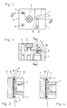
- a device for intermingling multifilament yarns has a two-part body with a nozzle body part 1 and an impact body part 2, which is attached to the nozzle body part 1 by means of a screw 3 and two centering pins 4 and 5.
- a continuous yarn channel 6 extends through the two-part body 1, 2 and is delimited by a first wall surface 7, which is concave in cross section, formed by a groove in the nozzle body part 1, and by a second hollow wall surface 8, formed by a groove in the impact body part 2
- the two wall surfaces 7 and 8 are each symmetrical with respect to a plane of symmetry which is identical to the sectional plane AA in FIG.
- the nozzle body part 1 contains a blowing nozzle 9, which opens into the side of the yarn channel approximately in the middle of the length of the yarn channel 6.
- the mouth of the blowing nozzle 9 lies in the first wall surface 7.
- the second wall surface 8 lies opposite the opening of the blowing nozzle 9.
- the axis of the blowing nozzle 9 is expediently in the plane of symmetry A - A.
- the nozzle body part 1 could also contain more than one blow nozzle.
- each blowing nozzle could be symmetrical with respect to the plane of symmetry A - A or, for example, two blowing nozzles could also be arranged symmetrically to one another on both sides of the plane A - A.
- the first wall surface 7 is curved in section with the plane of symmetry AA as shown in FIG. 3 such that the distance between the two wall surfaces 7 and 8 measured in the plane of symmetry AA is at a minimum at the mouth of the blowing nozzle 9 against both Ends of the yarn channel 6 gradually increases.
- the width of the yarn channel 6 measured perpendicular to the plane of symmetry A - A remains constant over the entire length of the yarn channel, the cross-sectional area of the yarn channel increases from a minimum size at the mouth of the blowing nozzle 9 towards both ends of the yarn channel, for example except for 1.2 to 4 times the minimum size, preferably 1.5 to 2 times the minimum size.
- the curvature of the first wall surface 7 extends such that the flow of the blowing medium from the mouth of the blowing nozzle 9 to the ends of the yarn channel 6 does not detach from the wall surface 7.
- the curve has no kinks, which means that the first derivative of the function mentioned is also a continuous function.
- the curvature of the curve should preferably not change abruptly; in other words, the second derivative of the function represented by the curve should preferably also be a continuous function (without jumps).
- a continuous threading slot 10 opens laterally into the yarn channel 6 between the two wall surfaces 7 and 8.
- the threading slot 10 lies between flat surfaces of the nozzle body part 1 and the impact body part 2.
- the yarn channel 6 ends at both ends in a groove 11 or 12.
- thread guide pins 13 or 14 are inserted outside the ends of the yarn channel, e.g. Sapphire pins that extend across grooves 11 and 12, respectively.
- a multifilament yarn M (FIG. 3), which runs through the yarn channel 6 during operation and is swirled by the blowing medium entering the yarn channel 6 from the blowing nozzle 9, is guided very precisely in the yarn channel 6.
- the thread guide pins have not been shown in FIG. 5.
- the second wall surface 8 extends beyond the ends of the yarn channel 6 to the outside.
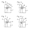
- FIGS. 4 and 6 differs from that according to FIGS. 1 to 3 and 5 only in that the second wall surface 8.1 is curved on average with the plane of symmetry, so that in the plane of symmetry measured distance between the two wall surfaces 7 and 8.1 towards the ends of the yarn channel 6 increases even more than in FIGS. 1 to 3 and 5.
- the curvature of the second wall surface 8.1 runs in the same manner as described above for the first wall surface 7 , so that the flow does not separate from the second wall surface 8.1.
- the first wall surface 7 is approximately V-shaped in cross-section with a rounded transition between the two V-legs
- FIG. 7 shows an embodiment in which the first wall surface 7.1 is approximately semi-circular in cross-section.
- the second wall surface 8 or 8.1 is hollow and approximately rectangular in cross section.
- the second wall surface 8.2 which delimits the yarn channel 6 upwards, is not formed by a groove in the impact body part 2, but simply by a section of the flat underside of the impact body part 2. Also here no threading slot is present between the underside of the impact body part 2 and the top of the nozzle body part 1.
Landscapes
- Engineering & Computer Science (AREA)
- Physics & Mathematics (AREA)
- Fluid Mechanics (AREA)
- Textile Engineering (AREA)
- Mechanical Engineering (AREA)
- Yarns And Mechanical Finishing Of Yarns Or Ropes (AREA)
- Nonwoven Fabrics (AREA)
- Spinning Methods And Devices For Manufacturing Artificial Fibers (AREA)
- Treatment Of Fiber Materials (AREA)
Abstract
Description
- Die Erfindung bezieht sich auf eine Vorrichtung zum Verwirbeln von Multifilamentgarnen gemäss dem Oberbegriff des Patentanspruchs 1.
- Die Aufgabe der Erfindung besteht darin, diese Vorrichtung derart auszubilden, dass damit im Vergleich mit bekannten Vorrichtungen eine gleichmässigere Verwirbelung von Multifilamentgarnen, insbesondere gleichmässigere Abstände zwischen den aufeinanderfolgenden Verwirbelungsstellen, und eine höhere Verwirbelungsdichte, gemessen in Verwirbelungsstellen pro Meter, erzielt werden können. Ferner soll je nach Wunsch die Bildung vieler und regelmässiger starker Verwirbelungsstellen pro Meter oder die Bildung vieler und regelmässiger schwacher Verwirbelungsstellen pro Meter möglich sein.
- Die Aufgabe wird in der erfindungsgemässen Vorrichtung dadurch gelöst, dass wenigstens eine der beiden Wandflächen in der Symmetrieebene derart gekrümmt ist, dass der in der Symmetrieebene gemessene Abstand zwischen den beiden Wandflächen von einem Minimum bei der Mündung der Blasdüse gegen beide Enden des Garnkanals hin allmählich zunimmt.
- In bekannten Verwirbelungsvorrichtungen übt die Energie des durch die Blasdüse zugeführten und durch den Garnkanal abströmenden Fluids, zumeist Luft, eine nachteilige Wirkung auf das verwirbelte Garn aus, indem sie zum Beispiel schwache Verwirbelungsstellen wieder auflöst und dadurch die Verwirbelung unregelmässig macht und gleichzeitig die Verwirbelungsdichte herabsetzt. Auch wird die Fadenspannung in dem an der Mündung der Blasdüse vorbeibewegten Garnabschnitt durch das nach beiden Enden des Garnkanals hin abströmende Fluid zusätzlich erhöht, was die Verwirbelung erschwert.
- In der erfindungsgemässen Vorrichtung ergibt sich durch die Vergrösserung des Abstandes zwischen den Wandflächen gegen die Enden des Garnkanals hin, wenn die Breite des Garnkanals in der bevorzugten Weise etwa konstant bleibt, eine entsprechende Vergrösserung der Querschnittsfläche des Garnkanals gegen die Enden hin. Verwirbelungsvorrichtungen werden üblicherweise so ausgelegt, dass sich in der Nähe der Mündung der Blasdüse nur ein unwesentlich höherer Druck als der ausserhalb der Vorrichtung herrschende Umgebungsdruck bildet. Nur so kann das Energiegefälle in der Vorrichtung effektiv genutzt werden. In der erfindungsgemässen Vorrichtung muss daher durch die Vergrösserung der Querschnittsfläche des Garnkanals gegen die Enden hin, da praktisch keine Druckabsenkung mehr möglich ist, nach der Kontinuitätsgleichung von Bernoulli eine Reduktion der Geschwindigkeit des abströmenden Mediums eintreten, weil die Vergrösserung der Querschnittsfläche gegen die Enden des Garnkanals hin allmählich erfolgt, so dass sich die Strömung nicht von den Wänden des Garnkanals ablöst. Die Geschwindigkeit geht in der Energieformel E = 1/2.m.v² im Quadrat ein. Bei Absenkung der Ausströmgeschwindigkeit des Fluids aus dem Garnkanal auf beispielsweise die Hälfte wird somit die schädliche Energie auf einen Viertel reduziert.
- Die Breite des Garnkanals, senkrecht zur Symmetrieebene gemessen, bleibt wie schon erwähnt vorzugsweise über die ganze Länge des Garnkanals im wesentlichen konstant. Die Beibehaltung der optimalen Garnkanalbreite bewirkt eine bessere Qualität der Verwirbelung und insbesondere eine hohe Verwirbelungsdichte. Der Blasstrahl teilt das Filamentbündel im Moment des Anpressens an die zweite Wandfläche in zwei etwa gleichgrosse Bündel auf, die erst in einem gewissen Abstand von der Blasdüse zu den beiderseits der Blasdüsenmündung sich bildenden Verwirbelungsknoten wieder zusammenfinden. Ein weiteres Spreizen der beiden Filamentbündel in einem Garnkanal, der sich gegen die Enden hin verbreitern würde, würde die Bildung der Verwirbelungsknoten weiter von der Blasdüse weg bewirken. Dadurch würde die Verwirbelungsdichte herabgesetzt, der Abstand zwischen den Verwirbelungsstellen würde grösser.
- Ausführungsbeispiele der erfindungsgemässen Vorrichtung werden nachstehend anhand der Zeichnungen näher erläutert. In diesen zeigen:
- Fig. 1 eine schematische Draufsicht auf den Körper einer Verwirbelungsvorrichtung, teilweise aufgebrochen,
- Fig. 2 einen Vertikalschnitt nach der Linie B - B in Fig. 1,
- Fig. 3 einen Vertikalschnitt nach der Schnittebene A - A in Fig. 2,
- Fig. 4 in einem ähnlichen Vertikalschnitt wie Fig. 3 eine abgewandelte Ausführungsform der Verwirbelungsvorrichtung,
- Fig. 5 eine Teil-Seitenansicht der in den Fig. 1 bis 3 gezeigten Vorrichtung,
- Fig. 6 eine Teil-Seitenansicht der Vorrichtung gemäss Fig. 4 und
- Fig. 7 und Fig. 8 ähnliche Teil-Seitenansichten wie Fig. 5 für zwei abgewandelte Ausführungsformen.
- Gemäss den Fig. 1 bis 3 und 5 besitzt eine Vorrichtung zum Verwirbeln von Multifilamentgarnen einen zweiteiligen Körper mit einem Düsenkörperteil 1 und einem Prallkörperteil 2, der mittels einer Schraube 3 und zweier Zentrierstifte 4 und 5 auswechselbar auf dem Düsenkörperteil 1 befestigt ist. Durch den zweiteiligen Körper 1, 2 erstreckt sich ein durchgehender Garnkanal 6, der begrenzt ist durch eine erste, im Querschnitt konkave Wandfläche 7, gebildet von einer Nut im Düsenkörperteil 1, und durch eine zweite hohle Wandfläche 8, gebildet von einer Nut im Prallkörperteil 2. Die beiden Wandflächen 7 und 8 sind je symmetrisch bezüglich einer Symmetrieebene, die mit der Schnittebene A - A in Fig. 2 identisch ist. Der Düsenkörperteil 1 enthält eine Blasdüse 9, die etwa in der Mitte der Länge des Garnkanals 6 seitlich in den Garnkanal einmündet. Die Mündung der Blasdüse 9 liegt in der ersten Wandfläche 7. Die zweite Wandfläche 8 liegt der Mündung der Blasdüse 9 gegenüber. Die Achse der Blasdüse 9 liegt zweckmässig in der Symmetrieebene A - A.
- Der Düsenkörperteil 1 könnte auch mehr als eine Blasdüse enthalten. In einem solchen Fall könnte jede Blasdüse bezüglich der Symmetrieebene A - A symmetrisch sein oder könnten auch beispielsweise zwei Blasdüsen zueinander symmetrisch auf beiden Seiten der Ebene A - A angeordnet sein.
- Die erste Wandfläche 7 ist im Schnitt mit der Symmetrieebene A - A wie in Fig. 3 dargestellt derart gekrümmt, dass der in der Symmetrieebene A - A gemessene Abstand zwischen den beiden Wandflächen 7 und 8 von einem Minimum bei der Mündung der Blasdüse 9 gegen beide Enden des Garnkanals 6 hin allmählich zunimmt. Dadurch nimmt, obwohl die senkrecht zur Symmetrieebene A - A gemessene Breite des Garnkanals 6 über die ganze Länge des Garnkanals konstant bleibt, die Querschnittsfläche des Garnkanals von einer Minimalgrösse bei der Mündung der Blasdüse 9 gegen beide Enden des Garnkanals hin zu, beispielsweise bis auf das 1,2- bis 4-fache der Minimalgrösse, vorzugsweise auf das 1,5- bis 2-fache der Minimalgrösse.
- Die Krümmung der ersten Wandfläche 7 verläuft derart, dass sich die Strömung des Blasmediums von der Mündung der Blasdüse 9 zu den Enden des Garnkanals 6 nicht von der Wandfläche 7 ablöst. Das heisst zunächst, dass die erste Wandfläche 7 im Schnitt mit der Symmetrieebene A - A nach einer Kurve verläuft, die eine stetige Funktion in Abhängigkeit von der Entfernung von der Mündung der Blasdüse 9 darstellt. Die Kurve weist keine Knicke auf, das heisst, dass auch die erste Ableitung der genannten Funktion eine stetige Funktion ist. Ferner sollte sich auch die Krümmung der Kurve vorzugsweise nicht sprunghaft ändern, es sollte mit anderen Worten auch die zweite Ableitung der von der Kurve dargestellten Funktion vorzugsweise eine stetige Funktion (ohne Sprünge) sein.
- In der in den Fig. 1 bis 3 und 5 dargestellten Ausführungsform mündet in den Garnkanal 6 zwischen den beiden Wandflächen 7 und 8 seitlich ein durchgehender Einfädelschlitz 10. Der Einfädelschlitz 10 liegt zwischen ebenen Oberflächen des Düsenkörperteils 1 und des Prallkörperteils 2.
- Im Düsenkörperteil 1 endet der Garnkanal 6 beiderends in je einer Nut 11 bzw. 12. In den Düsenkörperteil 1 sind ausserhalb der Enden des Garnkanals 6 Fadenführerstifte 13 bzw. 14 eingesetzt, z.B. Saphirstifte, die sich quer durch die Nuten 11 bzw. 12 erstrecken. Mit diesen Fadenführerstiften 13 und 14 ist ein Multifilamentgarn M (Fig. 3), das im Betrieb durch den Garnkanal 6 läuft und durch das aus der Blasdüse 9 in den Garnkanal 6 eintretende Blasmedium verwirbelt wird, im Garnkanal 6 sehr genau geführt. In Fig. 5 sind die Fadenführerstifte nicht eingezeichnet worden. Die zweite Wandfläche 8 erstreckt sich über die Enden des Garnkanals 6 hinaus nach aussen.
- Die in den Fig. 4 und,6 dargestellte Ausführungsform der erfindungsgemässen Vorrichtung unterscheidet sich von derjenigen gemäss den Fig. 1 bis 3 und 5 nur dadurch, dass auch die zweite Wandfläche 8.1 im Schnitt mit der Symmetrieebene gekrümmt ist, so dass der in der Symmetrieebene gemessene Abstand zwischen den beiden Wandflächen 7 und 8.1 gegen die Enden des Garnkanals 6 hin noch stärker zunimmt als in den Fig. 1 bis 3 und 5. Die Krümmung der zweiten Wandfläche 8.1 verläuft dabei in gleicher Weise stetig wie vorstehend für die erste Wandfläche 7 beschrieben, so dass sich auch von der zweiten Wandfläche 8.1 die Strömung nicht ablöst.
- Während in den Fig. 1 bis 6 die erste Wandfläche 7 im Querschnitt etwa V-förmig mit gerundetem Uebergang zwischen den beiden V-Schenkeln ist, zeigt Fig. 7 eine Ausführungsform, in welcher die erste Wandfläche 7.1 im Querschnitt etwa halbkreisförmig ist.
- In den bisher beschriebenen Ausführungsformen ist die zweite Wandfläche 8 bzw. 8.1 hohl und im Querschnitt etwa rechteckig. Demgegenüber ist in der Ausführungsform gemäss Fig. 8 die den Garnkanal 6 nach oben begrenzende zweite Wandfläche 8.2 nicht von einer Nut im Prallkörperteil 2 gebildet, sondern einfach von einem Abschnitt der ebenen Unterseite des Prallkörperteils 2. Auch ist hier zwischen der Unterseite des Prallkörperteils 2 und der Oberseite des Düsenkörperteils 1 kein Einfädelschlitz vorhanden.
Claims (10)
- Vorrichtung zum Verwirbeln von Multifilamentgarnen, mit einem Körper (1, 2), welcher einen durchgehenden Garnkanal (6) enthält, der begrenzt ist durch eine erste Wandfläche (7; 7.1), in welcher wenigstens eine Blasdüse (9) seitlich in den Garnkanal (6) einmündet und welche im Querschnitt konkav ist, und durch eine zweite Wandfläche (8; 8.1; 8.2), welche der Mündung der Blasdüse (9) gegenüberliegt, wobei jede der beiden Wandflächen bezüglich einer Symmetrieebene (A-A) symmetrisch ist, dadurch gekennzeichnet, dass wenigstens eine der beiden Wandflächen in der Symmetrieebene (A-A) derart gekrümmt ist, dass der in der Symmetrieebene (A-A) gemessene Abstand zwischen den beiden Wandflächen von einem Minimum bei der Mündung der Blasdüse (9) gegen beide Enden des Garnkanals (6) hin allmählich zunimmt.
- Vorrichtung nach Anspruch 1, dadurch gekennzeichnet, dass die Krümmung der wenigstens einen Wandfläche (7; 7.1; 8.1) so verläuft, dass Strömungsablösung von der Wandfläche vermieden wird.
- Vorrichtung nach Anspruch 2, dadurch gekennzeichnet, dass die Krümmung in der Symmetrieebene (A-A) nach einer Kurve verläuft, die eine stetige Funktion darstellt, von der auch die erste und die zweite Ableitung stetige Funktionen sind.
- Vorrichtung nach einem der Ansprüche 1 bis 3, dadurch gekennzeichnet, dass wenigstens die erste Wandfläche (7; 7.1) in der angegebenen Weise gekrümmt ist.
- Vorrichtung nach Anspruch 4, dadurch gekennzeichnet, dass auch die zweite Wandfläche (8.1) in der angegebenen Weise gekrümmt ist.
- Vorrichtung nach einem der Ansprüche 1 bis 5, dadurch gekennzeichnet, dass die senkrecht zur Symmetrieebene (A-A) gemessene Breite des Garnkanals (6) über die ganze Länge des Garnkanals wenigstens annähernd konstant bleibt.
- Vorrichtung nach einem der Ansprüche 1 bis 6, dadurch gekennzeichnet, dass die Querschnittsfläche des Garnkanals (6) von einer Minimalgrösse bei der Mündung der Blasdüse (9) gegen beide Enden des Garnkanale hin bis auf das 1,2- bis 4-fache, vorzugsweise auf das 1,5- bis 2-fache, der Minimalgrösse zunimmt.
- Vorrichtung nach einem der Ansprüche 1 bis 7, dadurch gekennzeichnet, dass in den Körper (1, 2) ausserhalb der beiden Enden des Garnkanals (6) Fadenführerelemente (13, 14) eingesetzt sind.
- Vorrichtung nach einem der Ansprüche 1 bis 8, dadurch gekennzeichnet, dass sich die zweite Wandfläche (8; 8.1; 8.2) über die Enden des Garnkanals (6) hinaus fortsetzt.
- Vorrichtung nach einem der Ansprüche 1 bis 9, dadurch gekennzeichnet, dass im Körper (1, 2) ein Einfädelschlitz (10) ausgebildet ist, der zwischen den beiden Wandflächen (7, 8) seitlich in den Garnkanal (6) einmündet.
Applications Claiming Priority (2)
| Application Number | Priority Date | Filing Date | Title |
|---|---|---|---|
| CH109992 | 1992-04-03 | ||
| CH1099/92 | 1992-04-03 |
Publications (2)
| Publication Number | Publication Date |
|---|---|
| EP0564400A1 true EP0564400A1 (de) | 1993-10-06 |
| EP0564400B1 EP0564400B1 (de) | 1995-12-06 |
Family
ID=4202458
Family Applications (1)
| Application Number | Title | Priority Date | Filing Date |
|---|---|---|---|
| EP93810193A Expired - Lifetime EP0564400B1 (de) | 1992-04-03 | 1993-03-17 | Vorrichtung zum Verwirbeln von Multifilamentgarnen |
Country Status (6)
| Country | Link |
|---|---|
| EP (1) | EP0564400B1 (de) |
| JP (1) | JP2751947B2 (de) |
| KR (1) | KR100200408B1 (de) |
| CN (1) | CN1039730C (de) |
| DE (1) | DE59301070D1 (de) |
| RU (1) | RU2095496C1 (de) |
Cited By (5)
| Publication number | Priority date | Publication date | Assignee | Title |
|---|---|---|---|---|
| EP0633334A1 (de) * | 1993-07-10 | 1995-01-11 | TEMCO TEXTILMASCHINENKOMPONENTEN GmbH & Co. KG | Vorrichtung zum Verwirbeln von Filamenten |
| US6052878A (en) * | 1999-05-28 | 2000-04-25 | E. I. Du Pont De Nemours And Company | Methods and apparatus for interlacing filaments and methods of making the apparatus |
| US6834417B1 (en) | 1999-03-03 | 2004-12-28 | Heberlein Fibertechnology, Inc. | Method and device for processing filament yarn, and use of said device |
| US7426820B2 (en) | 2003-12-02 | 2008-09-23 | Giudici S.P.A. | Method and device for the production of a covered elastic yarn and for automatic replacement of feeds spools |
| CN114959983A (zh) * | 2022-05-11 | 2022-08-30 | 宜兴市阿芙勒尔陶瓷科技有限公司 | 一种加弹机网络喷嘴配件的工作方法 |
Families Citing this family (8)
| Publication number | Priority date | Publication date | Assignee | Title |
|---|---|---|---|---|
| DE19700817C2 (de) * | 1996-01-12 | 1999-02-11 | Heberlein Fasertech Ag | Verfahren und Verwirbelungsdüse zur Herstellung von spinntexturierten Filamentgarnen |
| US5950290A (en) * | 1997-09-12 | 1999-09-14 | International Machinery Sales, Inc. | Jet for interlacing textile yarns |
| EP1411014A1 (de) | 2002-10-17 | 2004-04-21 | Giudici S.p.a. | Verfahren und Vorrichtung zur Herstellung von elastischen Umwindegarnen und zum automatischen Wechsel von Lieferspulen |
| TWI301518B (en) * | 2004-06-30 | 2008-10-01 | Oerlikon Heberlein Temco Wattwil Ag | Device and process for the treatment of filament yarn |
| ITBI20040004A1 (it) * | 2004-10-12 | 2005-01-12 | Sinterama S P A | Dispositivo ad elevato rendimento per l'interlacciatura ad aria di un filo, e relativo metodo |
| DE102012003410A1 (de) | 2012-02-23 | 2013-08-29 | Rpe Technologies Gmbh | Garnbehandlungsvorrichtung |
| ITUA20164462A1 (it) * | 2016-06-17 | 2017-12-17 | Sergio Zaglio | Dispositivo interlacciatore e relativo metodo |
| DE102019001545A1 (de) * | 2019-03-05 | 2020-09-10 | Oerlikon Textile Gmbh & Co. Kg | Verwirbelungsvorrichtung zum Verwirbeln eines synthetischen, multifilen Fadens |
Citations (2)
| Publication number | Priority date | Publication date | Assignee | Title |
|---|---|---|---|---|
| DE2917218A1 (de) * | 1978-04-28 | 1979-11-22 | Snia Viscosa | Verfahren und vorrichtung zum verflechten eines mehrfadengarns |
| EP0465407A1 (de) * | 1990-07-02 | 1992-01-08 | Heberlein Maschinenfabrik AG | Vorrichtung zum Verwirbeln von Multifilamentgarnen |
Family Cites Families (1)
| Publication number | Priority date | Publication date | Assignee | Title |
|---|---|---|---|---|
| JPS602513B2 (ja) * | 1978-07-07 | 1985-01-22 | 三菱自動車工業株式会社 | 内燃機関の吸気通路構造 |
-
1993
- 1993-03-17 DE DE59301070T patent/DE59301070D1/de not_active Expired - Fee Related
- 1993-03-17 EP EP93810193A patent/EP0564400B1/de not_active Expired - Lifetime
- 1993-03-30 KR KR1019930005064A patent/KR100200408B1/ko not_active IP Right Cessation
- 1993-04-01 JP JP5075561A patent/JP2751947B2/ja not_active Expired - Fee Related
- 1993-04-02 RU RU9393004762A patent/RU2095496C1/ru not_active IP Right Cessation
- 1993-04-02 CN CN93103506A patent/CN1039730C/zh not_active Expired - Fee Related
Patent Citations (2)
| Publication number | Priority date | Publication date | Assignee | Title |
|---|---|---|---|---|
| DE2917218A1 (de) * | 1978-04-28 | 1979-11-22 | Snia Viscosa | Verfahren und vorrichtung zum verflechten eines mehrfadengarns |
| EP0465407A1 (de) * | 1990-07-02 | 1992-01-08 | Heberlein Maschinenfabrik AG | Vorrichtung zum Verwirbeln von Multifilamentgarnen |
Cited By (5)
| Publication number | Priority date | Publication date | Assignee | Title |
|---|---|---|---|---|
| EP0633334A1 (de) * | 1993-07-10 | 1995-01-11 | TEMCO TEXTILMASCHINENKOMPONENTEN GmbH & Co. KG | Vorrichtung zum Verwirbeln von Filamenten |
| US6834417B1 (en) | 1999-03-03 | 2004-12-28 | Heberlein Fibertechnology, Inc. | Method and device for processing filament yarn, and use of said device |
| US6052878A (en) * | 1999-05-28 | 2000-04-25 | E. I. Du Pont De Nemours And Company | Methods and apparatus for interlacing filaments and methods of making the apparatus |
| US7426820B2 (en) | 2003-12-02 | 2008-09-23 | Giudici S.P.A. | Method and device for the production of a covered elastic yarn and for automatic replacement of feeds spools |
| CN114959983A (zh) * | 2022-05-11 | 2022-08-30 | 宜兴市阿芙勒尔陶瓷科技有限公司 | 一种加弹机网络喷嘴配件的工作方法 |
Also Published As
| Publication number | Publication date |
|---|---|
| JP2751947B2 (ja) | 1998-05-18 |
| DE59301070D1 (de) | 1996-01-18 |
| KR100200408B1 (ko) | 1999-06-15 |
| EP0564400B1 (de) | 1995-12-06 |
| CN1039730C (zh) | 1998-09-09 |
| CN1079264A (zh) | 1993-12-08 |
| JPH0617359A (ja) | 1994-01-25 |
| RU2095496C1 (ru) | 1997-11-10 |
| KR930021842A (ko) | 1993-11-23 |
Similar Documents
| Publication | Publication Date | Title |
|---|---|---|
| EP0465407B1 (de) | Vorrichtung zum Verwirbeln von Multifilamentgarnen | |
| EP0564400B1 (de) | Vorrichtung zum Verwirbeln von Multifilamentgarnen | |
| DE3612229C2 (de) | ||
| EP0383722B1 (de) | Verwirbelungsdüse zum Verwirbeln von Multifilament garnen | |
| CH619010A5 (de) | ||
| DE3713813C2 (de) | ||
| DE2937182C2 (de) | Luftstrahl-Düsenwebmaschine | |
| CH650478A5 (de) | Verfahren und vorrichtung zum spleissen von zwei garn- oder fadenenden. | |
| DE2739431C3 (de) | Luftlenkender Kamm für eine Düsenwebmaschine | |
| DE3113592C2 (de) | Schussfaden-Eintragvorrichtung für eine Düsenwebmaschinen | |
| CH663431A5 (de) | Schusseintragseinrichtung fuer duesenwebmaschine. | |
| EP0716171B1 (de) | Schussfadenstreck- und Detektiereinrichtung für Düsenwebmaschinen | |
| EP0383037B1 (de) | Vorrichtung zum schwebenden Führen von Materialbahnen durch gegen die Materialbahn geblasene Luft | |
| DE3010249C2 (de) | Düsenwebmaschine | |
| DE2658844A1 (de) | Stoffauflaufvorrichtung fuer eine papiermaschine | |
| DE3151900A1 (de) | Vorrichtung zum eintragen eines schussfadens in das webfach einer pneumatischen webmaschine | |
| DE3010387C2 (de) | Luftdüse zum Erzeugen verwirbelten mehrfädigen Garns | |
| WO1996033304A1 (de) | Webmaschine | |
| DE4105448A1 (de) | Vorrichtung zur verbindung von texilfaeden und textilgarnen mit anwendung von druckluft | |
| DE2840177A1 (de) | Verwirbelungsduese | |
| DE60217443T2 (de) | Eintragsdüse für eine Luftdüsenwebmaschine | |
| DE19751354C1 (de) | Hilfsblasdüse für eine Luftdüsenwebmaschine | |
| DD233870A1 (de) | Verfahren und vorrichtung zum entfernen von fluessigkeiten aus laufenden endlosen faeden | |
| DE3034120C2 (de) | Eintragskanal für eine Düsenwebmaschine | |
| DE19947894C1 (de) | Vorrichtung zum Verwirbeln von Multifilamentgarnen |
Legal Events
| Date | Code | Title | Description |
|---|---|---|---|
| PUAI | Public reference made under article 153(3) epc to a published international application that has entered the european phase |
Free format text: ORIGINAL CODE: 0009012 |
|
| AK | Designated contracting states |
Kind code of ref document: A1 Designated state(s): CH DE FR GB IT LI |
|
| 17P | Request for examination filed |
Effective date: 19931231 |
|
| 17Q | First examination report despatched |
Effective date: 19940805 |
|
| GRAA | (expected) grant |
Free format text: ORIGINAL CODE: 0009210 |
|
| ITF | It: translation for a ep patent filed |
Owner name: BARZANO' E ZANARDO ROMA S.P.A. |
|
| AK | Designated contracting states |
Kind code of ref document: B1 Designated state(s): CH DE FR GB IT LI |
|
| REF | Corresponds to: |
Ref document number: 59301070 Country of ref document: DE Date of ref document: 19960118 |
|
| GBT | Gb: translation of ep patent filed (gb section 77(6)(a)/1977) |
Effective date: 19960116 |
|
| ET | Fr: translation filed | ||
| PLBE | No opposition filed within time limit |
Free format text: ORIGINAL CODE: 0009261 |
|
| STAA | Information on the status of an ep patent application or granted ep patent |
Free format text: STATUS: NO OPPOSITION FILED WITHIN TIME LIMIT |
|
| 26N | No opposition filed | ||
| REG | Reference to a national code |
Ref country code: CH Ref legal event code: NV Representative=s name: ERNST ACKERMANN PATENTANWALT |
|
| REG | Reference to a national code |
Ref country code: CH Ref legal event code: PFA Free format text: HEBERLEIN MASCHINENFABRIK AG TRANSFER- HEBERLEIN FASERTECHNOLOGIE AG |
|
| REG | Reference to a national code |
Ref country code: GB Ref legal event code: IF02 |
|
| PGFP | Annual fee paid to national office [announced via postgrant information from national office to epo] |
Ref country code: FR Payment date: 20040322 Year of fee payment: 12 |
|
| PG25 | Lapsed in a contracting state [announced via postgrant information from national office to epo] |
Ref country code: FR Free format text: LAPSE BECAUSE OF NON-PAYMENT OF DUE FEES Effective date: 20051130 |
|
| REG | Reference to a national code |
Ref country code: FR Ref legal event code: ST Effective date: 20051130 |
|
| PGFP | Annual fee paid to national office [announced via postgrant information from national office to epo] |
Ref country code: DE Payment date: 20060301 Year of fee payment: 14 |
|
| PGFP | Annual fee paid to national office [announced via postgrant information from national office to epo] |
Ref country code: IT Payment date: 20060331 Year of fee payment: 14 |
|
| PGFP | Annual fee paid to national office [announced via postgrant information from national office to epo] |
Ref country code: CH Payment date: 20060415 Year of fee payment: 14 |
|
| PGFP | Annual fee paid to national office [announced via postgrant information from national office to epo] |
Ref country code: GB Payment date: 20060424 Year of fee payment: 14 |
|
| REG | Reference to a national code |
Ref country code: CH Ref legal event code: PL |
|
| GBPC | Gb: european patent ceased through non-payment of renewal fee |
Effective date: 20070317 |
|
| PG25 | Lapsed in a contracting state [announced via postgrant information from national office to epo] |
Ref country code: DE Free format text: LAPSE BECAUSE OF NON-PAYMENT OF DUE FEES Effective date: 20071002 |
|
| PG25 | Lapsed in a contracting state [announced via postgrant information from national office to epo] |
Ref country code: CH Free format text: LAPSE BECAUSE OF NON-PAYMENT OF DUE FEES Effective date: 20070331 Ref country code: LI Free format text: LAPSE BECAUSE OF NON-PAYMENT OF DUE FEES Effective date: 20070331 |
|
| PG25 | Lapsed in a contracting state [announced via postgrant information from national office to epo] |
Ref country code: GB Free format text: LAPSE BECAUSE OF NON-PAYMENT OF DUE FEES Effective date: 20070317 |
|
| PG25 | Lapsed in a contracting state [announced via postgrant information from national office to epo] |
Ref country code: IT Free format text: LAPSE BECAUSE OF NON-PAYMENT OF DUE FEES Effective date: 20070317 |