EP0558281B1 - Contrôleur de réglage coordonné pour les deux terminaux de manipulation - Google Patents
Contrôleur de réglage coordonné pour les deux terminaux de manipulation Download PDFInfo
- Publication number
- EP0558281B1 EP0558281B1 EP93301342A EP93301342A EP0558281B1 EP 0558281 B1 EP0558281 B1 EP 0558281B1 EP 93301342 A EP93301342 A EP 93301342A EP 93301342 A EP93301342 A EP 93301342A EP 0558281 B1 EP0558281 B1 EP 0558281B1
- Authority
- EP
- European Patent Office
- Prior art keywords
- signal
- switching means
- difference
- control
- control operation
- Prior art date
- Legal status (The legal status is an assumption and is not a legal conclusion. Google has not performed a legal analysis and makes no representation as to the accuracy of the status listed.)
- Expired - Lifetime
Links
Images


Classifications
-
- G—PHYSICS
- G05—CONTROLLING; REGULATING
- G05B—CONTROL OR REGULATING SYSTEMS IN GENERAL; FUNCTIONAL ELEMENTS OF SUCH SYSTEMS; MONITORING OR TESTING ARRANGEMENTS FOR SUCH SYSTEMS OR ELEMENTS
- G05B7/00—Arrangements for obtaining smooth engagement or disengagement of automatic control
- G05B7/02—Arrangements for obtaining smooth engagement or disengagement of automatic control electric
Definitions
- This invention relates to a modulating controller for controlling two operation terminals, and more particularly to a device to suppress disturbance to a process when a control signal is switched or when a bias is set.
- FIG. 1 shows a conventional modulating controller, and this modulating controller controls operation terminals each disposed in a branched channel.
- the operation terminal is a flow control valve for example.
- This channel is parted into branch lines 2A, 2B on its way.
- the branch lines 2A, 2B are provided with operation terminals 3A, 3B respectively.
- orifice 4 is provided in the joined channel. Differential pressure before and after the orifice is detected by sensor 5.
- This detected signal is subjected to the calculation of extraction of the square root, and inputted into modulating controller 1 as a measured value of this flow rate.
- the modulating controller 1 conducts control-operation so that the operation terminals 3A, 3B share a half of the flow rate needed, and the operation terminal 3A control signal and the operation terminal 3B control signal are outputted to the corresponding operation terminals 3A, 3B to control the flow rate of the channel at a certain value.
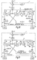
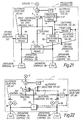
- Fig. 2 shows a construction of a specific modulating controller 1.
- the modulating controller 1 comprises setting signal generator means 6, difference operation means 7, PID operation means 8, and two H/A station 9A. 9B.
- the difference operation means 7 operates a difference signal between the detection signal of the sensor 5 and the set signal of the setting signal generator means 6. This difference signal is entered into the PID operation means 8.
- the PID operation means 8 conducts operation treatments of proportion, integral and differential based on this difference signal, and outputs PID control signal.
- This PID control signal becomes the operation terminal 3A control signal and the operation terminal 3B control signal via two H/A station 9A, 9B. According to the operation terminal 3A control signal and the operation terminal 3B control signal, the corresponding operation terminals 3A, 3B are controlled.
- the operation terminals 3A, 3B When the operation terminals 3A, 3B are manually operated, a manual section provided on the H/A station 9A, 9B is operated.
- the operation terminals 3A, 3B When automatic operation signal is inputted into the H/A station 9A, 9B, the operation terminals 3A, 3B are controlled to be opened or closed by the PID control signal.
- the H/A station 9A, 9B have functions to switch to a signal by manual operation or PID control signal. Therefore, the operation terminals 3A, 3B can operate separately by manual operation other than PID control signal.
- the operation terminals 3A, 3B use the same equipment. Even if the same equipment is used, characteristics may vary slightly depending on each equipment. In such a case, in order to compensate the characteristics of equipment, a bias setting is made to one of the operation terminal control signals.
- FIG. 3 is an example of a control block diagram having bias setting means 10.
- the system on the operation terminal 3B side has a bias function.
- the bias setting means 10 has plus or minus bias setting signal set.
- Addition means 11 adds the bias setting signal to the PID control signal and outputs.
- the valve of each operation terminal to be used is a valve which can flow the base flow or more.
- one operation terminal only is automatically operated and the other operation terminal is manually operated.
- the device of FIG. 4 has mean value operation means 13A provided.
- the mean value operation means 13A operates the average of the operation terminal 3A control signal and the operation terminal 3B control signal, and outputs a tracking signal to the PID operation means 8.
- the device of FIG. 5 is provided with high selector means 13B.
- the high selector means 13B selects the high vales of output of the operation terminal 3A control signal and the operation terminal 3B control signal, and outputs a tracking signal to the PID operation means 8.
- the device of FIG. 6 is provided with low selector means 13C.
- the low selector means 13C selects the low values of output of the operation terminal 3A control signal and the operation terminal 3B control signal, and outputs a tracking signal to the PID operation means 8.
- the devices shown in FIG. 4 and FIG. 5 have structure to make the tracking condition generator signal an ON signal when the automatic selection A and the automatic selection signal B are execution halt signal (OFF signal). When this tracking condition generator signal is ON signal, the tracking signal is inputted in the PID operation means 8 and tracked to the integral element of the PID operation means 8.
- conventional modulating controller 1 shown in FIG. 2 has the operation terminal 3A control signal and the operation terminal 3B control signal equal under an ordinary condition that the H/A station 9A, 9B are under automatic operation. And, two operation terminals 3A, 3B shares the flow rate into a half to control so that the flow rate becomes equal to the set signal.
- the control input of the manual operation to the flow rate which has been shared in half by the operation terminal 3A and the operation terminal 3B gives disturbance to the process system resulting in varying the process system.
- conventional modulating controller 1 shown in FIG. 3 when bias setting is operated by bias setting means 10, from a state that the operation terminals 3A, 3B flow the flow rate in half to control, the bias control input content disturbs the process system.
- Such a conventional device had a problem to jive disturbance to the process system of the plant every time the bias operation was conducted.
- the mean value of the operation terminal 3A control signal and operation terminal 3B control signal is tracked. Therefore, whichever of the operation terminal 3A control signal and operation terminal 3B control signal is switched to automatic operation, bumping is made to the mean value, and automatic operation is started from the mean value.
- This bumping between the operation terminal 3A control signal and the operation terminal 3B control signal becomes disturbance against the plant, making the plant to a dangerous condition.
- EP-A-0 139 243 DE-C-40 16 017 (& US-A-5 195 027), US-A-4 469 994, and US-A-3 940 594.
- An object of this invention is to provide a modulating controller which can simply switch the operation between automatic (control operation signal, e.g. PID control signal) and other control signals (e.g. manual control signal) and reduce disturbance to the process system.
- automatic control operation signal
- other control signals e.g. manual control signal
- a modulating controller in accordance with the invention is defined in claim 1.
- the control operation signal e.g. PID control signal
- the control operation signal e.g. PID control signal
- the one operation terminal is operated by the other control signal (e.g. manual operation signal)
- a value obtained by reducing the other control signal value (e.g. manual operation value) from the entire control amount is sent as the control operation signal to the other operation terminal, so that the disturbance given to the process can be made small.
- a means which always tracks one operation terminal control signal to the control operation means when the both operation terminals are the other control signal (e.g. manual operation signal). Therefore, switching can be made without bumping one of the operation terminals to the automatic operation.
- the other operation terminal is switched to the automatic operation, there is preferably provided a means which delays the timing to switch the other operation terminal to the automatic operation and the timing to release the tracking. During which, the tracking signal is switched to the output of the other operation terminal, so that switching can be made without bumping the other operation terminal to the automatic operation.
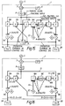
- FIG. 7 is a schematic block diagram showing the first embodiment of the modulating controller of this invention.
- the reference numerals same with those used in FIG. 2 show the same parts or corresponding parts, the modulating controller 1 shown in the first embodiment is subjected to the two operation terminals of the plant shown in FIG. 1, and the operation terminal is the same rated flow rate and can flow the flow rate of not less than 100% in the total flow rate of the two operation terminals.
- the modulating controller 1 comprises the setting signal generator means 6, the difference operation means 7, control operation means 8, preceding adjusting means 14, signal switching means 9A, 9B (e.g. H/A station or signal transfer), and mean value operation means 16.
- the setting signal generator means 6 outputs a certain set signal.
- the difference operation means 7 calculates the difference between the detection signal of the sensor 5 and the set signal of the setting signal generator means 6 and outputs the difference signal.
- the control operation means 8 inputs the difference signal, calculates proportion, integral and differential, and outputs as the PID control signal (first control operation signal).
- the preceding adjusting means 14 comprises difference operation means 17A, 17B, adjusting means 18, and addition means 19A, 19B.
- the preceding adjusting means 14 precedingly compensates the control signal of the operation terminal to the PID control signal, and can smoothly switch to a different control signal.
- the signal switching means 9A, 9B switches the signal from the addition means 19A, 19B and the other control signal (second control operation signal, e.g. manual operation signal) under a certain condition, and outputs the operation terminal control signal to the corresponding operation terminal 3A or operation terminal 3B.
- the difference operation means 17A calculates the difference between the PID control signal and the operation terminal 3B control signal and outputs the difference signal.
- the difference operation means 17B calculates the difference between the PID control signal and the operation terminal 3A control signal and outputs the difference signal.
- the adjusting means 18 inputs the difference signal of the difference operation means 17B and controls a time lag when returning from the manual operation to the automatic operation by the PID control signal.
- the addition means 19A adds the PID control signal and the difference signal of the difference operation means 17A.
- the addition means 19B adds the PID control signal and the signal through the difference operation means 17B or adjusting means 18.
- the mean value operation means 16 executes tracking when both signal switching means 9A, 9B are manually operated.
- the mean value operation means 16 calculates the mean value of the operation terminal 3A control signal and the operation terminal 3B control signal and tracks the integral element of the control operation means 8 based on this mean value.
- FIG. 7 the first embodiment shown in FIG. 7 will be described in detail with reference to the block diagram shown in FIG. 8.
- the difference operation means 17B reduces from the PID control signal the operation terminal 3A control signal from the signal switching means 9A and obtains the difference between the PID control signal and the operation terminal 3A control signal.
- the difference becomes positive or negative.
- both of the signal switching means 9A, 9B are automatically operated, the difference becomes substantially 0%.
- preceding signal transfer means 18A When both of the signal switching means 9A, 9B are automatically operated, preceding signal transfer means 18A outputs 0%. When either of the signal switching means 9A, 9B is manually operated, the preceding signal transfer means 18A outputs the output signal of the difference operation means 17B as it is.
- the lag means 18C when the signal switching means 9A, 9B are automatically operated, gives a primary time lag to the output signal of the preceding signal transfer means 18A and outputs.
- the output signal of the preceding signal transfer means 18A bypasses the lag means 18C and is entered in the preceding signal transfer means 18B, then outputted from the preceding signal transfer means 18B as it is.
- the output signal of the preceding signal transfer means 18A is tracked to the integral element of the lag means 18C.
- the addition means 19B adds the PID control signal and the output signal of the preceding signal transfer means 18B.
- the signal switching means 9B ouputs the output signal of the addition means 19B as it is when under automatic operation, and outputs the signal manually operated by the operator when not under automatic operation.
- the difference operation means 17A reduces the operation terminal 3B control signal from the PID control signal, and obtains the difference between the PID control signal and the operation terminal 3B control signal.
- the difference becomes positive or negative.
- both of the signal switching means 9A, 9B are automatically operated, the difference becomes substantially 0%.
- the addition means 19A adds the PID control signal and the output signal of the difference operation means 17A.
- the signal switching means 9A outputs the output signal of the addition means 19A as it is under manual operation, and outputs the signal manually operated by the operator when not automatically operated.
- Fixed value output means 18D outputs the signal of 0%.
- the mean value operation means 16 when both of the signal switching means 9A, 9B are manually operated, tracks the integral element of the control operation means 8 based on the value obtained by calculating the mean of the operation terminal 3A control signal and the operation terminal 3B control signal.
- CV compensation means is omitted in this embodiment.
- the CV compensation means is designed to be disposed on the modulating controller 1.
- the PID control signal which is an output of the control operation means 8 shall be D
- FIG. 12 is a diagram which is an extract of the control block only executed when the signal switching means 9A and the signal switching means 9B are manually operated in FIG. 8.
- the preceding signal transfer means 18A outputs (B - A)/2 .
- the preceding signal transfer means 18A selects 0% of the fixed value output means 18D. And, the control system has been already stabilized and the output of the preceding signal transfer means 18B has also reached 0%. Therefore, the addition means 19B outputs 30% by the addition of 30% of the PID control signal and 0% of the output of the preceding signal transfer means 18B. As the signal switching means 9B is automatically operated, 30% is outputted as it is, and the operation terminal 3B control signal becomes 30%.
- the difference operation means 17A calculates the difference between 30% of the PID control signal and 30% of the operation terminal 3B control signal and outputs 0%.
- the addition means 19A adds 30% of the PID control signal and 0% of the output of the difference operation means 17A and outputs 30%. As the signal switching means 9A is automatically operated, 30% is outputted as it is, As described above, the PID control signal is stably outputted to both of the operation terminals 3A, 3B in 30%.
- the signal switching means 9A becomes manual operation and gradually lowers the operation terminal 3A control signal, and at time t2, the operation terminal 3A control signal is supposed to become 10%.
- the control block of FIG. 10 is applied.
- the difference operation means 17B calculates the difference between 30% of the PID control signal and 10% of the operation terminal 3A control signal.
- the preceding signal transfer means 18B also outputs 20%.
- the lag means 18C has a value of 20% tracked.
- the addition means 19B adds 30% of the PID control signal and 20% of the output of the preceding signal transfer means 18B and outputs 50%.
- the signal switching means 9B Since the signal switching means 9B is automatically operated, 50% is outputted as it is, and the operation terminal 3B control signal becomes 50%. At this time, the operation terminal 3A control signal is manually operated from 30% to 10%, so that the operation terminal 3B control signal gradually changes from 30% to 50% correspondingly, and at time t2, it becomes 50%. Thus, the opening of the operations terminals required to flow the flow rate corresponding to 60% to both operations terminals 3A, 3B, large disturbance is not given to the process.
- the difference operation means 17A calculates the difference between 30% of the PID control signal and 50% of the operation terminal 3B control signal and outputs -20%.
- the addition means 19A adds 30% of the PID control signal and -20% of the output of the difference operation means 17A and outputs 10%. Then, at time t2, the output of the addition means 19A is equal to the opening 10% of manual operation. Therefore, under this condition, even if the signal switching means 9A is suddenly returned to automatic operation, the operation terminal 3A control signal is switched without bump.
- the output of the lag means 18C becomes 0%.
- the operation terminal 3A control signal becomes 30% which is equal to the PID control signal.
- the output of the difference operation means 17A increases from -20% to 0%, and the operation terminal 3A control signal is also returned gradually to 30% of the PID control signal.
- sum of the openings of the operation terminals 3A, 3B is always 60%. This is a value equal to two times of the PID control signal, and means to have kept the opening required to obtain the flow rate corresponding to 60%. Therefore, when compared with the conventional device shown in FIG. 2, disturbance given to the process system is quite small.
- FIG. 14 is a schematic block diagram showing the second embodiment of the modulating controller of this invention.
- the reference numerals same with those used in FIG. 3 show the same parts or corresponding parts.
- the modulating controller 1 shown in the second embodiment is subjected to the two operation terminals of the plant shown in FIG. 1, the operation terminals are the same rated flow rate, and can flow the flow rate of 100% or more in total of the two operation terminals.
- the modulating controller comprises the setting signal generator means 6, the difference operation means 7, the control operation means 8, the preceding adjusting means 14, the signal switching means (e.g. H/A station or signal transfer) 9A, 9B, and the mean value operation means 16.
- the preceding adjusting means 14 comprises the difference operation means 17A, 17B, the bias setting means 22, the adjusting means 18, and the addition means 19A, 19B.
- the setting signal generator means 6 outputs a certain set signal.
- the difference operation means 7 calculates the difference between the detection signal of the sensor and the set signal of the setting signal generator means 6 and outputs the difference signal.
- the control operation means 8 inputs the difference signal, calculates proportion, integral and differential, and outputs as the PID control signal (first control operation signal).
- the difference operation means 17B reduces from the PID control signal the operation terminal 3A control signal from the signal switching means 9A, and obtains the difference between the PID control signal and the operation terminal 3A control signal.
- the preceding signal transfer means 18A When both of the signal switching means 9A, 9B are automatically operated, the preceding signal transfer means 18A outputs the bias value set by the bias setting means 22. When either of the signal switching means 9A, 9B is manually operated, the preceding signal transfer means 18A outputs the output of the difference operation means 17B as it is.
- the lag means 18C when both of the signal switching means 9A, 9B are automatically operated, outputs the output signal of the preceding signal transfer means 18A with a primary delay. When either of the signal switching means 9A, 9B is manually operated, the output signal of the preceding signal transfer means 18A bypasses the lag means 18C and inputted in the preceding signal transfer means 18B, then outputted from the preceding signal transfer means 18B as it is. And, the output signal of the preceding signal transfer means 18A is tracked to the integral element of the lag means 18C.
- the addition means 19B adds the PID control signal and the output signal of the preceding signal transfer means 18B.
- the signal switching means 9B outputs the output signal of the addition means 19B as it is when automatically operated and outputs the signal manually operated by the operator when not automatically operated.
- the difference operation means 17A reduces the operation terminal 3B control signal from the PID control signal, and obtains the difference between the PID control signal and the operation terminal 3B control signal.
- the addition means 19A adds the PID control signal and the output signal of the difference operation means 17A.
- the signal switching means 9A outputs the output signal of the addition means 19A as it is when automatically operated and outputs the signal manually operated by the operator when not automatically operated.
- the mean value operation means 16 tracks the integral elements of the control operation means 8.
- the PID control signal which is an output of the control operation means 8 shall be D
- FIG. 19 is a diagram which is an extract of the control block only executed when the signal switching means 9A and the signal switching means 9B are manually operated in FIG. 15.
- the control block of FIG. 16 is applied. Between time t0 and time t1, to obtain the flow rate corresponding to 60%, the control system is stabilized in the state that the PID control signal of 30% is respectively outputted to the operation terminals 3A, 3B.
- the bias set signal shall be +/- 0%.
- the addition means 19B outputs 30% of the PID control signal.
- the operation terminal 3B control signal becomes 30%.
- the difference operation means 17A calculates the difference between 30% of the PID control signal and 30% of the operation terminal 3B control signal, and outputs 0%.
- the addition means 19A adds 30% of the PID control signal and 0% of the output of the difference operation means 17A, and outputs 30%. As the signal switching means 9A is automatically operated, 30% is outputted as it is.
- the bias set signal is +/- 0%. And, 30% of the PID control signal is respectively outputted to the operation terminals 3A, 3B, and the control system is stabilized.
- the control block of FIG. 16 is applied.
- the bias setting means 22 outputs +20%, and the preceding signal transfer means 18A also outputs + 20%.
- the lag means 18C has +20% inputted. And, the lag means 18C gradually changes from 0% to +20% with the primary delay and outputs. This output of the lag means 18C is inputted in the preceding signal transfer means 18B.
- the preceding signal transfer means 18B outputs the inputted signal as it is.
- the addition means 19B adds the PID control signal and the signal outputted by the preceding signal transfer means 18B and outputs.
- the addition means 19B gradually outputs 30% -> 50%.
- the signal switching means 9B is under automatic operation, its output varies from 30% to 50%, and the operation terminal 3B control signal varies fro 30% of time t1 to 50% of time t2.
- the difference operation means 17A calculates the difference between 30% of the PID control signal and 30% -> 50% of the operation terminal 3B control signal and outputs 0% -> -20%. And, the addition means 19A adds 30% of the PID control signal and 0% -> -20% of the output of the difference operation means 17A and outputs 30 -> 10%. As the signal switching means 9A is automatically operated, 30% -> 10% are outputted. At this time, the calculation results of the difference operation means 17B vary from 0% to 20% according to the change of the operation terminal 3A control signal from 30% to 10%. Therefore, when the bias setting is made during the automatic operation of both of the signal switching means 9A, 9B, in stationary state, the output of the difference operation means 17B becomes equal to the bias set signal.
- the signal switching means 9A is automatically operated. Then, shift is made from the control block of FIG. 16 to the control block of FIG. 19. Specifically, when the signal switching means 9A becomes under manual operation, the input of the preceding signal transfer means 18A is switched from the input of the bias setting signal to the input of the difference operation means 17B. At the time, the bias set signal (20%) is equal to the output signal (20%) of the difference operation means 17B. 20% of the output signal of this difference operation means 17B is inputted in the addition means 19B through the preceding signal transfer means 18B. The addition means 19B is outputted in 50% to the signal switching means 9B. Therefore, even when the signal switching means 9A becomes manual operation, the operation terminal 3B does not change.
- the difference operation means 17A inputs 50% of B and 30% of the PID control signal and outputs -20%. And, as the addition means 19A outputs 10%, switching is made from automatic operation to manual operation without bump, Then, the operation amount of the signal switching means 9A is gradually increased to reach 30% in time t4, and kept at a certain level, then the operation terminal 3B control signal of the signal switching means 9B is also stabilized.
- the bias set value can be added to one operation terminal, and the other operation terminal operates to compensate the bias set value added content Therefore, total of the operation terminal control signals to the operation terminals 3A, 3B does not change. Therefore, disturbance given to the process can be suppressed to the minimum, and the control system can be stabilized sooner.
- the lag means 18C was described by the operation with the primary delay, but this does not restrict the invention to this.
- a rate limitter can be used.
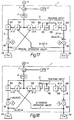
- FIG. 21 is a schematic block diagram showing the third embodiment of the modulating controller of this invention.
- the third embodiment is an example that the operation terminal A and the operation terminal B can flow the rated flow rate or more with one valve respectively. As the backup for one operation terminal, the other operation terminal is provided. And, the third embodiment has the construction that either one of the operation terminals is automatically operated in the plant structure shown in FIG. 1. And, the operation terminal control signal under automatic operation is tracked to the output value of manual operation by another means not shown.
- the modulating controller 1 comprises the setting signal generator means 6, the difference operation means 7, the control operation means 8, the signal switching means (e.g. H/A station or signal transfer) 9A, 9B, time lag means 23 (e.g. on delay timer), tracking condition means 24, and signal switching means 25.
- the signal switching means e.g. H/A station or signal transfer
- time lag means 23 e.g. on delay timer
- tracking condition means 24 e.g. on delay timer
- the setting signal generator means 6 outputs a certain set signal.
- the difference operation means 7 calculates the difference between the detected signal of the sensor 5 and the set signal of the setting signal generator means 6 and outputs the difference signal.
- the control operation means 8 inputs the difference signal, calculates proportion, integral and differential, and output as the PID control signal (first control operation signal).
- the control operation means 8 outputs the PID control signal to either one of the two operation terminals and controls the process amount.
- the signal switching means 9A switched from the other control signal (second control operation signal, e.g. manual operation signal) to the PID control signal. And, when the automatic selection signal A becomes an operation stopping signal (OFF signal), the signal switching means 9A switches from the PID control signal to the other control signal. The output of the signal switching means 9A is outputted to the operation terminal 3A as the operation terminal 3A control signal.
- the time lag means 23 when the automatic selection signal B to output the PID control signal to the operation terminal 3B becomes the operatable signal (ON signal) and after a certain time, outputs the operatable signal (ON signal) of switching condition signal B.
- the on delay timer means When the automatic selection signal B becomes the operation stopping signal (OFF signal), the on delay timer means outputs the operation stopping signal (OFF signal) of the switching condition signal B.
- the signal switching means 9B switches to the control operation signal when the switching condition signal B becomes the operatable signal (ON signal).
- the switching condition signal B becomes the operation stopping signal (OFF signal)
- the signal switching means 9B switches to the other control signal (second control operation signal e.g. manual operation signal).
- the output of the signal switching means 9B is outputted to the operation terminal 3B as the operation terminal control 3B signal.
- the signal switching means 25 switches to the operation terminal 3A control signal when the automatic selection signal A becomes the operatable signal (ON signal).
- the signal switching means 25 switches to the operation terminal 3B control signal. And, the signal switching means 25 outputs the tracking signal to track to the PID control signal to the control operation means 8.
- the automatic selection signal B is the operation stopping signal (OFF signal). Therefore, in this embodiment, the signal switching means 25 inputs the automatic selection signal B only as the condition to switch the signal. And the signal switching means 25 switches to the operation terminal 3B control signal when the automatic selection signal B is the operatable signal (ON signal), and switches to the operation terminal 3A control signal when the automatic selection signal B is the operation stopping signal (OFF signal).
- the tracking condition means 24 when both of the automatic selection signal A and the switching condition signal B become the operation stopping signal (OFF signal), outputs the tracking condition signal to track the tracking signal to the PID control signal to the control operation means 8.
- the difference operation means 7 calculates the difference between the measured signal value from the sensor 5 and the set signal of the setting signal generator means 6.
- the control operation means 8 outputs the PID control signal according to the difference signal, the signal switching means 9A, 9B switch to the automatic operation when each automatic selection signal is ON signal, and switch to the manual operation when the automatic selection signal is OFF signal.
- the time lag means 23 outputs the switching condition signal B with a delay of a certain time when the automatic selection signal B is ON signal, as the condition signal to switch the signal switching means 9B to the automatic operation.
- the signal switching means 9B is switched to the automatic operation a certain time after the automatic selection signal B becomes ON signal.
- the automatic selection signal B becomes OFF signal, it instantly switches to the manual operation.
- the tracking condition means 24 calculates the tracking execution condition to the control operation means 8.
- the tracking condition means 24 outputs the condition to execute the tracking by the completion of logical product of NOT of ON signal of the automatic selection signal A and NOT of ON signal of the automatic selection signal B.
- the signal switching means 25 outputs the tracking signal by switching to the operation terminal 3A control signal when the automatic selection signal B is OFF signal and by switching to the operation terminal 3B control signal when the automatic selection signal B is ON signal.
- the signal switching means 9A is manually operated, the operation terminal 3A control signal is 30%, the signal switching means 9B is manually operated, and the operation terminal 3B control signal is 60% during time t0 to time t1.
- both of the automatic selection signals A, B are OFF signal, the signal switching means 25 outputs the operation terminal 3A control signal, the control operation means 8 is tracked by the operation terminal 3A control signal, and the PID control signal is 30%.
- the signal switching means 9A is switched to the automatic operation.
- the control operation means 8 starts the PID control from the tracked 30%, the operation terminal 3A control signal shifts to the PID control without bumping. And, it gradually approaches to the set signal.
- the signal switching means 9A is manually operated, the operation terminal 3A control signal is 30%, the signal switching means 9B is manually operated, and the operation terminal 3B control signal is 60%.
- the signal switching means 25 is immediately switched from the operation terminal 3A control signal (30%) to the operation terminal 3B control signal (60%). Therefore, the tracking signal from the signal switching means 25 to the control operation means 8 varies from 30% to 60%.
- the transfer condition signal B inputted in the tracking condition means 24 from the time lag means 23 becomes ON signal.
- the tracking condition signal becomes OFF signal, and tracking of the control operation means 8 is released.
- the control operation means 8 shifts to the PID control signal based on the difference signal and outputs 60%.
- the transfer condition signal B of the signal switching means 9B also becomes ON signal.
- the output of the signal switching means 9B is switched to the PID control signal and shifts to the PID control from 60% without bumping.
- the signal switching means was used to cut off the PID control signal on its way, but it can be similarly executed by switching to the other control signal is outputted by the other device not shown by an interlock or the like.
- the operation terminal on the PID controlling side in the opening fixing control that one operation terminal has the opening changed stepwisely at the moment switched to the other control signal, the operation terminal on the PID controlling side is also operated in the reverse direction stepwisely.
- the required opening in the total of the both operation terminals 3A, 3B, the required opening is secured but, as the control signal to the both operation terminals 3A, 3B is outputted stepwisely, disturbance of the process system is assumed to be larger than the above description.
- control operation means was the PID operation means but this invention is not limited to this and it may be the PI operation means.
- the operation terminal was the flow control valve but this invention is not limited to this and it may be a fan, pump, compressor, motor and so on.
- the control operation signal e.g. the PID control signal
- the control operation signal is precedingly compensated by the other operation terminal control signal. Therefore, when the other control signal is switched to the control operation signal, disturbance to the process can be suppressed to the minimum and the control system can be stabilized soon.
- the value obtained by reducing the value (e.g. the manual operation value) of the other control signal from the whole control amount is sent to the other operation terminal as the control operation signal, so that disturbance given to the process can be suppressed to be small.
- the mean value of one operation terminal control signal and the other operation terminal control signal is calculated, and as this mean value signal is tracked to the control operation signal, when either of the operation terminals is switched to the automatic operation, switching is made without bumping.
- the second embodiment when both of the operation terminals are automatically operated, when one operation terminal is subjected to the bias setting, operation is made so that the entire control operation signal to the both operation terminals is always balanced. Even when the bias set signal is changed, as the following is made with a certain lag, disturbance to the process system can be suppressed to the minimum, and the control system can be stabilized.
- one operation terminal when the both operation terminals are manually operated, as one operation terminal control signal is tracked to the control operation signal, one operation terminal can be switched to the automatic operation without bumping. Further. when the other operation terminal is switched to the automatic operation, timing to switch the other operation terminal to the automatic operation and timing to release the tracking are delayed and, during which, the tracking signal is switched to the output of the other operation terminal, so that the other operation terminal can be also switched to the automatic operation without bumping.
Landscapes
- Physics & Mathematics (AREA)
- General Physics & Mathematics (AREA)
- Engineering & Computer Science (AREA)
- Automation & Control Theory (AREA)
- Feedback Control In General (AREA)
Claims (13)
- Contrôleur de modulation (1) pour commander une quantité de traitement en commandant deux bornes d'opération (3A, 3B) disposées en parallèle, comprenant :des moyens d'opération de différence (7) pour fournir un signal de différence représentant la différence entre la quantité de traitement et un signal fixé de la quantité de traitement ;des moyens d'opération PID (8) pour recevoir le signal de différence provenant desdits moyens d'opération de différence et pour sortir un premier signal d'opération de commande pour commander chacune desdites deux bornes d'opération ;des premiers et seconds moyens de commutation de signal (9A, 9B), correspondant respectivement auxdites deux bornes d'opération, pour effectuer une commutation entre le premier signal d'opération de commande et un second signal d'opération de commande comme un signal de commande manuel, et pour sortir un signal de commande de borne d'opération vers chacune desdites deux bornes d'opération ;des moyens de réglage précédents (14) caractérisés par :lorsque l'un desdits premiers et seconds moyens de commutation de signal sort le second signal d'opération de commande en tant que signal de commande de borne d'opération, la sortie vers l'autre desdits premiers et seconds moyens de commutation de signal d'un signal d'opération de commande modifié obtenu en soustrayant le second signal d'opération de commande de la quantité totale du premier signal d'opération de commande dans la condition où lesdites deux bornes d'opération sont toutes deux commandées par le premier (non modifié) signal d'opération de commande, et l'application à l'un desdits premiers et seconds moyens de commutation de signal du premier signal d'opération de commande pratiquement de la même valeur que le second signal d'opération de commande.
- Contrôleur de modulation selon la revendication 1 dans lequel lesdits moyens de réglage précédents (14), lorsque soit l'un ou l'autre desdits premiers et seconds moyens de commutation de signal est passé de l'état de sortie dudit second signal d'opération de commande à l'état dans lequel lesdits premiers et seconds moyens de commutation de signal sont tous deux commutés vers ledit premier signal d'opération de commande, comprennent des moyens pour décaler graduellement ledit premier signal d'opération de commande à sortir vers lesdits premiers moyens de commutation de signal et ledit premier signal d'opération de commande à sortir vers lesdits seconds moyens de commutation de signal mutuellement à des valeurs pratiquement égales.
- Contrôleur de modulation selon la revendication 1, dans lequel lesdits moyens de réglage précédents (14), lorsque lesdits premiers et seconds moyens de commutation de signal sortent tous deux ledit second signal de commande en tant que signal de commande de borne d'opération, comprennent des moyens pour préparer une valeur sensiblement identique au signal de commande de borne d'opération sorti par les moyens de commutation de signal respectifs pour lesdits deux moyens de commutation de signal comme ledit premier signal d'opération de commande.
- Contrôleur de modulation selon la revendication 1, comprenant, de plus, des moyens de détermination de polarisation (22) pour fixer une valeur de polarisation.
- Contrôleur de modulation selon la revendication 4, dans lequel lesdits moyens de réglage précédents (14), lorsque l'un ou l'autre desdits premiers et seconds moyens de commutation de signal est passé de l'état de sortie dudit second signal de commande à l'état dans lequel les premiers et seconds moyens de commutation de signal sont tous deux commutés vers ledit premier signal d'opération de commande, comprennent des moyens pour décaler graduellement ledit premier signal d'opération de commande à sortir vers lesdits premiers moyens de commutation de signal et ledit premier signal d'opération à sortir vers lesdits seconds moyens de commutation de signal à une valeur augmentée ou diminuée de ladite valeur de polarisation déterminée.
- Contrôleur de modulation selon la revendication 5, dans lequel ladite valeur de polarisation déterminée est nulle.
- Contrôleur de modulation selon la revendication 1, dans lequel lesdits moyens de réglage précédents (14) comprennent :des premiers moyens d'opération de différence (17A) pour fournir, en tant que premier signal de différence, la différence entre ledit premier signal d'opération de commande et le signal de commande de borne d'opération sorti par les seconds moyens de commutation de signal (9B) ;des seconds moyens d'opération de différence (17B) pour fournir, en tant que second signal de différence, la différence entre ledit premier signal d'opération de commande et le signal de commande de borne d'opération sorti par les premiers moyens de commutation de signal (9A) ;des moyens de réglage (18) pour sortir ledit second signal de différence inchangé et pour retenir le second signal de différence lorsque l'un ou l'autre desdits premiers et seconds moyens de commutation de signal sort le second signal d'opération de commande, et pour sortir, en décalant graduellement vers zéro à partir de la valeur du signal retenu lorsque ledit un des premiers et seconds moyens de commutation de signal sortant le second signal d'opération de commande commute vers ledit premier signal d'opération de commande ;des premiers moyens d'addition (19A) pour additionner ledit premier signal de différence et ledit premier signal d'opération de commande et pour sortir un premier résultat d'addition vers lesdits premiers moyens de commutation de signal ; etdes seconds moyens d'addition (19B) pour additionner la sortie desdits moyens de réglage et ledit premier signal d'opération de commande et pour sortir un second résultat d'addition vers lesdits seconds moyens de commutation de signal.
- Contrôleur de modulation selon la revendication 1, dans lequel lesdits moyens de réglage précédents (14) comprennent :des premiers moyens d'opération de différence (17A) pour fournir, en tant que premier signal de différence, la différence entre ledit premier signal d'opération de commande et le signal de commande de borne d'opération sorti par les seconds moyens de commutation de signal ;des seconds moyens d'opération de différence (17B) pour fournir, en tant que second signal de différence, la différence entre ledit premier signal d'opération de commande et le signal de commande de borne d'opération sorti par les premiers moyens de commutation de signal ;des moyens de réglage (18) pour sortir ledit second signal de différence inchangé et pour suivre le second signal de différence vers l'élément intégral de moyens de retard lorsque l'un ou l'autre desdits premiers et seconds moyens de commutation de signal sort le second signal d'opération de commande, et pour entrer zéro vers lesdits moyens de retard et pour sortir, en décalant graduellement vers zéro à partir de la valeur dudit second signal de différence lorsque ledit un des premiers et seconds moyens de commutation de signal sortant le second signal d'opération de commande commute vers ledit premier signal d'opération de commande ;des premiers moyens d'addition (19A) pour additionner ledit premier signal de différence et ledit premier signal d'opération de commande et pour sortir un premier résultat d'addition vers lesdits premiers moyens de commutation de signal ; etdes seconds moyens d'addition (19B) pour additionner la sortie desdits moyens de réglage et ledit premier signal d'opération de commande et pour sortir un second résultat d'addition vers lesdits seconds moyens de commutation de signal.
- Contrôleur de modulation selon la revendication 1, dans lequel lesdits moyens de réglage précédents comprennent :des premiers moyens d'opération de différence pour fournir, on tant que premier signal de différence, la différence entre ledit premier signal d'opération de commande et le signal de commande de borne d'opération sorti par les seconds moyens de commutation de signal ;des seconds moyens d'opération de différence pour fournir, en tant que second signal de différence, la différence entre ledit premier signal d'opération de commande et le signal de commande de borne d'opération sorti par les premiers moyens de commutation de signal ;des moyens de détermination de polarisation pour déterminer une valeur de polarisation ;des moyens de réglage pour sortir ledit second signal de différence inchangé et pour retenir le second signal de différence lorsque l'un ou l'autre desdits premiers et seconds moyens de commutation de signal sort le second signal d'opération de commande, et pour sortir en décalant graduellement vers ladite valeur de polarisation à partir de la valeur du signal retenu lorsque ledit un des premiers et seconds moyens de commutation de signal sortant le second signal d'opération de commande commute vers ledit premier signal d'opération de commande ;des premiers moyens d'addition pour additionner ledit premier signal de différence et ledit premier signal d'opération de commande et pour sortir un premier résultat d'addition vers lesdits premiers moyens de commutation de signal ; etdes seconds moyens d'addition pour additionner la sortie desdits moyens de réglage et ledit premier signal d'opération de commande et pour sortir un second résultat d'addition vers lesdits seconds moyens de commutation de signal.
- Contrôleur de modulation selon la revendication 1, dans lequel les moyens de réglage précédents comprennent :des premiers moyens d'opération de différence pour fournir, en tant que premier signal de différence, la différence entre ledit premier signal d'opération de commande et le signal de commande de borne d'opération sorti par les seconds moyens de commutation de signal ;des seconds moyens d'opération de différence pour fournir, en tant que second signal de différence, la différence entre ledit premier signal d'opération de commande et le signal de commande de borne d'opération sorti par les premiers moyens de commutation de signal ;des moyens de détermination de polarisation pour déterminer une valeur de polarisation ;des moyens de réglage pour sortir ledit second signal de différence inchangé et pour suivre le second signal de différence vers l'élément intégral de moyens de retard lorsque l'un ou l'autre desdits premiers et seconds moyens de commutation de signal sort le second signal d'opération de commande, et pour entrer ladite valeur de polarisation vers lesdits moyens de retard et pour sortir en décalant graduellement vers ladite valeur de polarisation à partir de la valeur dudit second signal de différence lorsque ledit un des premiers et seconds moyens de commutation de signal sortant le second signal d'opération de commande commute vers ledit premier signal d'opération de commande ;des premiers moyens d'addition pour additionner ledit premier signal de différence et ledit premier signal d'opération de commande et pour sortir un premier résultat d'addition vers lesdits premiers moyens de commutation de signal ; etdes seconds moyens d'addition pour additionner la sortie desdits moyens de réglage et ledit premier signal d'opération de commande et pour sortir un second résultat d'addition vers lesdits seconds moyens de commutation de signal.
- Contrôleur de modulation selon la revendication 7, 8, 9 ou 10, comprenant, de plus, des moyens d'opération de valeur moyenne pour calculer une valeur moyenne du second signal d'opération de commande sorti desdits premiers et seconds moyens de commutation de signal et pour suivre cette valeur moyenne vers l'élément intégral desdits moyens d'opération de commande lorsque lesdits premiers et seconds moyens de commutation de signal sortent tous deux le second signal d'opération de commande.
- Contrôleur de modulation selon la revendication 1, dans lequel lesdits moyens de réglage précédents comprennent :des moyens pour entrer, en tant que signal de suivi, ledit signal de commande de borne d'opération sorti par lesdits premiers moyens de commutation de signal vers lesdits moyens d'opération de commande lorsque lesdits premiers et seconds moyens de commutation de signal sortent ledit second signal de commande en tant que signal de commande de borne d'opération ;des moyens de retard pour retarder une synchronisation selon laquelle les seconds moyens de commutation de signal commutent vers ledit premier signal d'opération de commande et une synchronisation pour cesser le suivi lorsque lesdits seconds moyens de commutation de signal sont commutés vers ledit premier signal d'opération de commande ; etdes moyens pour commuter le signal de suivi entré dans ledit signal d'opération de commande vers la sortie desdits seconds moyens de commutation de signal lorsque lesdits moyens de retard agissent.
- Contrôleur de modulation selon la revendication 1, dans lequel les moyens de commutation précédents comprennent :des moyens de retard pour sortir un signal vers lesdits seconds moyens de commutation de signal après un certain temps de réception de ce signal pour commuter le signal de commande de borne d'opération sorti par lesdits seconds moyens de commutation de signal vers ledit premier signal d'opération de commande ;des troisièmes moyens de commutation de signal pour sortir un signal qui est sorti par lesdits premiers moyens de commutation de signal et pour sortir un signal qui est sorti par lesdits seconds moyens de commutation de signal pendant la réception dudit signal ne passant pas à travers lesdits moyens de retard et pour commuter le signal de commande de borne d'opération sorti par lesdits seconds moyens de commutation de signal vers ledit premier signal d'opération de commande ; etdes moyens de condition de suivi pour suivre le signal sorti par lesdits troisièmes moyens de commutation de signal vers lesdits moyens d'opération de commande lorsque ledit signal pour commuter le signal de commande de borne d'opération sorti par lesdits seconds moyens de commutation de signal vers ledit premier signal d'opération de commande et ledit signal pour commuter le signal d'opération de commande sorti par lesdits seconds moyens de commutation de signal sorti par lesdits moyens de retard ne sont pas un signal pour commuter vers ledit premier signal d'opération de commande.
Applications Claiming Priority (6)
| Application Number | Priority Date | Filing Date | Title |
|---|---|---|---|
| JP7573792 | 1992-02-28 | ||
| JP75737/92 | 1992-02-28 | ||
| JP7573792 | 1992-02-28 | ||
| JP341059/92 | 1992-11-30 | ||
| JP34105992A JPH05303402A (ja) | 1992-02-28 | 1992-11-30 | 調整制御装置 |
| JP34105992 | 1992-11-30 |
Publications (3)
| Publication Number | Publication Date |
|---|---|
| EP0558281A2 EP0558281A2 (fr) | 1993-09-01 |
| EP0558281A3 EP0558281A3 (en) | 1997-01-22 |
| EP0558281B1 true EP0558281B1 (fr) | 2000-08-30 |
Family
ID=26416893
Family Applications (1)
| Application Number | Title | Priority Date | Filing Date |
|---|---|---|---|
| EP93301342A Expired - Lifetime EP0558281B1 (fr) | 1992-02-28 | 1993-02-23 | Contrôleur de réglage coordonné pour les deux terminaux de manipulation |
Country Status (4)
| Country | Link |
|---|---|
| US (1) | US5490058A (fr) |
| EP (1) | EP0558281B1 (fr) |
| CA (1) | CA2090572C (fr) |
| DE (1) | DE69329306T2 (fr) |
Families Citing this family (21)
| Publication number | Priority date | Publication date | Assignee | Title |
|---|---|---|---|---|
| JP3486427B2 (ja) * | 1993-01-18 | 2004-01-13 | キヤノン株式会社 | 制御装置および制御方法 |
| US6317637B1 (en) * | 1998-10-22 | 2001-11-13 | National Instruments Corporation | System and method for maintaining output continuity of PID controllers in response to changes in controller parameters |
| US7749089B1 (en) | 1999-02-26 | 2010-07-06 | Creative Kingdoms, Llc | Multi-media interactive play system |
| US7445550B2 (en) | 2000-02-22 | 2008-11-04 | Creative Kingdoms, Llc | Magical wand and interactive play experience |
| US7878905B2 (en) | 2000-02-22 | 2011-02-01 | Creative Kingdoms, Llc | Multi-layered interactive play experience |
| US6761637B2 (en) | 2000-02-22 | 2004-07-13 | Creative Kingdoms, Llc | Method of game play using RFID tracking device |
| US7066781B2 (en) | 2000-10-20 | 2006-06-27 | Denise Chapman Weston | Children's toy with wireless tag/transponder |
| US20070066396A1 (en) | 2002-04-05 | 2007-03-22 | Denise Chapman Weston | Retail methods for providing an interactive product to a consumer |
| US6967566B2 (en) | 2002-04-05 | 2005-11-22 | Creative Kingdoms, Llc | Live-action interactive adventure game |
| US7674184B2 (en) | 2002-08-01 | 2010-03-09 | Creative Kingdoms, Llc | Interactive water attraction and quest game |
| US7109608B2 (en) * | 2002-09-11 | 2006-09-19 | Visteon Global Technologies, Inc. | Advanced smooth transition switch |
| US9446319B2 (en) | 2003-03-25 | 2016-09-20 | Mq Gaming, Llc | Interactive gaming toy |
| US8313379B2 (en) | 2005-08-22 | 2012-11-20 | Nintendo Co., Ltd. | Video game system with wireless modular handheld controller |
| US7927216B2 (en) * | 2005-09-15 | 2011-04-19 | Nintendo Co., Ltd. | Video game system with wireless modular handheld controller |
| JP4805633B2 (ja) | 2005-08-22 | 2011-11-02 | 任天堂株式会社 | ゲーム用操作装置 |
| US8870655B2 (en) * | 2005-08-24 | 2014-10-28 | Nintendo Co., Ltd. | Wireless game controllers |
| JP4262726B2 (ja) * | 2005-08-24 | 2009-05-13 | 任天堂株式会社 | ゲームコントローラおよびゲームシステム |
| US8308563B2 (en) | 2005-08-30 | 2012-11-13 | Nintendo Co., Ltd. | Game system and storage medium having game program stored thereon |
| US8157651B2 (en) | 2005-09-12 | 2012-04-17 | Nintendo Co., Ltd. | Information processing program |
| JP4151982B2 (ja) | 2006-03-10 | 2008-09-17 | 任天堂株式会社 | 動き判別装置および動き判別プログラム |
| JP5127242B2 (ja) | 2007-01-19 | 2013-01-23 | 任天堂株式会社 | 加速度データ処理プログラムおよびゲームプログラム |
Citations (1)
| Publication number | Priority date | Publication date | Assignee | Title |
|---|---|---|---|---|
| US4469994A (en) * | 1983-04-11 | 1984-09-04 | General Electric Company | Reference signal circuit |
Family Cites Families (13)
| Publication number | Priority date | Publication date | Assignee | Title |
|---|---|---|---|---|
| US3940594A (en) * | 1974-08-13 | 1976-02-24 | Beckman Instruments, Inc. | Automatic process controller with bumpless operation |
| JPS5346581A (en) * | 1976-10-08 | 1978-04-26 | Yokogawa Hokushin Electric Corp | Recording/indicating controller |
| CA1108731A (fr) * | 1977-05-13 | 1981-09-08 | Herbert N Klingbeil | Circuit de commande multiple avec point de consigne flottant |
| US4525041A (en) * | 1982-02-24 | 1985-06-25 | Precision Grinding Limited | Arrangement for use in positioning an optical image |
| US4500950A (en) * | 1982-04-12 | 1985-02-19 | Westinghouse Electric Corp. | Industrial process control apparatus and method |
| JPS59226901A (ja) * | 1983-06-07 | 1984-12-20 | Mitsubishi Heavy Ind Ltd | 状態制御方式 |
| JPS6069702A (ja) * | 1983-09-26 | 1985-04-20 | Toshiba Corp | サンプル値プロセス制御装置 |
| US4649539A (en) * | 1985-11-04 | 1987-03-10 | Honeywell Information Systems Inc. | Apparatus providing improved diagnosability |
| EP0291615B1 (fr) * | 1987-04-22 | 1992-07-01 | International Business Machines Corporation | Commande séquentielle programmable pour gestion de procédés rapides complexes |
| FR2635390B1 (fr) * | 1988-08-12 | 1990-10-12 | Bull Sa | Unite centrale pour systeme de traitement de l'information |
| US4901625A (en) * | 1989-01-03 | 1990-02-20 | Increcyl, Inc. | Apparatus and method for positioning equipment |
| DE4016017C1 (fr) * | 1990-05-18 | 1991-10-17 | Eckardt Ag, 7000 Stuttgart, De | |
| US5191521A (en) * | 1990-06-18 | 1993-03-02 | Controlsoft, Inc. | Modular multivariable control apparatus and method |
-
1993
- 1993-02-23 DE DE69329306T patent/DE69329306T2/de not_active Expired - Fee Related
- 1993-02-23 EP EP93301342A patent/EP0558281B1/fr not_active Expired - Lifetime
- 1993-02-25 US US08/022,464 patent/US5490058A/en not_active Expired - Fee Related
- 1993-02-26 CA CA002090572A patent/CA2090572C/fr not_active Expired - Fee Related
Patent Citations (1)
| Publication number | Priority date | Publication date | Assignee | Title |
|---|---|---|---|---|
| US4469994A (en) * | 1983-04-11 | 1984-09-04 | General Electric Company | Reference signal circuit |
Also Published As
| Publication number | Publication date |
|---|---|
| DE69329306D1 (de) | 2000-10-05 |
| US5490058A (en) | 1996-02-06 |
| EP0558281A2 (fr) | 1993-09-01 |
| EP0558281A3 (en) | 1997-01-22 |
| DE69329306T2 (de) | 2001-03-01 |
| CA2090572C (fr) | 1997-07-15 |
| CA2090572A1 (fr) | 1993-08-29 |
Similar Documents
| Publication | Publication Date | Title |
|---|---|---|
| EP0558281B1 (fr) | Contrôleur de réglage coordonné pour les deux terminaux de manipulation | |
| US5504672A (en) | Industrial process controller and method of process control | |
| US4587470A (en) | Multiplex control system | |
| US4408148A (en) | Controller for a lockable servo motor | |
| US5706193A (en) | Control system, especially for a non-linear process varying in time | |
| EP0318006B1 (fr) | Système de commande automatique | |
| GB2393051A (en) | A stand-alone process controller changeover switch which operates smoothly by use of feedback | |
| JPH05303402A (ja) | 調整制御装置 | |
| JPH08101716A (ja) | 回転速度制御装置 | |
| US4283670A (en) | Automatic integrator control for transientless switching of _controller gains in manual tracking systems | |
| US5001644A (en) | Throttle split monitor for aircraft with intermixed engines | |
| JPH0474201A (ja) | プロセス制御装置 | |
| Hui et al. | New design methods of actuator saturation compensators for proportional, integral and derivative controllers | |
| Boyce | Multivariable cascade control for processes with output constraints | |
| JPS60233301A (ja) | タ−ビン制御装置 | |
| JPH09282001A (ja) | 手動切替え機能を有する制御装置 | |
| JPH03133222A (ja) | 送信電力制御装置 | |
| JPH075929A (ja) | 調節弁制御装置 | |
| JPH04215104A (ja) | フィードバック制御装置 | |
| JPH0849505A (ja) | 蒸気弁試験装置 | |
| JPH03288202A (ja) | 多重系制御システム | |
| JP2965658B2 (ja) | タービン制御方法 | |
| SU1640667A1 (ru) | Релейно-импульсный регул тор | |
| JPH087441Y2 (ja) | 流量制御装置 | |
| JPS5898603A (ja) | タ−ビン制御装置 |
Legal Events
| Date | Code | Title | Description |
|---|---|---|---|
| PUAI | Public reference made under article 153(3) epc to a published international application that has entered the european phase |
Free format text: ORIGINAL CODE: 0009012 |
|
| 17P | Request for examination filed |
Effective date: 19930305 |
|
| AK | Designated contracting states |
Kind code of ref document: A2 Designated state(s): DE GB |
|
| PUAL | Search report despatched |
Free format text: ORIGINAL CODE: 0009013 |
|
| AK | Designated contracting states |
Kind code of ref document: A3 Designated state(s): DE GB |
|
| 17Q | First examination report despatched |
Effective date: 19980309 |
|
| GRAG | Despatch of communication of intention to grant |
Free format text: ORIGINAL CODE: EPIDOS AGRA |
|
| RIC1 | Information provided on ipc code assigned before grant |
Free format text: 6G 05B 7/02 A |
|
| RIC1 | Information provided on ipc code assigned before grant |
Free format text: 6G 05B 7/02 A |
|
| GRAG | Despatch of communication of intention to grant |
Free format text: ORIGINAL CODE: EPIDOS AGRA |
|
| GRAH | Despatch of communication of intention to grant a patent |
Free format text: ORIGINAL CODE: EPIDOS IGRA |
|
| GRAH | Despatch of communication of intention to grant a patent |
Free format text: ORIGINAL CODE: EPIDOS IGRA |
|
| GRAA | (expected) grant |
Free format text: ORIGINAL CODE: 0009210 |
|
| AK | Designated contracting states |
Kind code of ref document: B1 Designated state(s): DE GB |
|
| REF | Corresponds to: |
Ref document number: 69329306 Country of ref document: DE Date of ref document: 20001005 |
|
| EN | Fr: translation not filed | ||
| PGFP | Annual fee paid to national office [announced via postgrant information from national office to epo] |
Ref country code: GB Payment date: 20010221 Year of fee payment: 9 |
|
| PLBE | No opposition filed within time limit |
Free format text: ORIGINAL CODE: 0009261 |
|
| STAA | Information on the status of an ep patent application or granted ep patent |
Free format text: STATUS: NO OPPOSITION FILED WITHIN TIME LIMIT |
|
| 26N | No opposition filed | ||
| REG | Reference to a national code |
Ref country code: GB Ref legal event code: IF02 |
|
| PG25 | Lapsed in a contracting state [announced via postgrant information from national office to epo] |
Ref country code: GB Free format text: LAPSE BECAUSE OF NON-PAYMENT OF DUE FEES Effective date: 20020223 |
|
| PGFP | Annual fee paid to national office [announced via postgrant information from national office to epo] |
Ref country code: DE Payment date: 20020314 Year of fee payment: 10 |
|
| GBPC | Gb: european patent ceased through non-payment of renewal fee |
Effective date: 20020223 |
|
| PG25 | Lapsed in a contracting state [announced via postgrant information from national office to epo] |
Ref country code: DE Free format text: LAPSE BECAUSE OF NON-PAYMENT OF DUE FEES Effective date: 20030902 |