EP0556552B1 - Verfahren zum Herstellen von Hohlkörpern aus thermoplastischem Kunststoff sowie Hohlkörper aus thermoplastischem Kunststoff - Google Patents
Verfahren zum Herstellen von Hohlkörpern aus thermoplastischem Kunststoff sowie Hohlkörper aus thermoplastischem Kunststoff Download PDFInfo
- Publication number
- EP0556552B1 EP0556552B1 EP93100355A EP93100355A EP0556552B1 EP 0556552 B1 EP0556552 B1 EP 0556552B1 EP 93100355 A EP93100355 A EP 93100355A EP 93100355 A EP93100355 A EP 93100355A EP 0556552 B1 EP0556552 B1 EP 0556552B1
- Authority
- EP
- European Patent Office
- Prior art keywords
- wall
- hollow body
- holding means
- process according
- additional body
- Prior art date
- Legal status (The legal status is an assumption and is not a legal conclusion. Google has not performed a legal analysis and makes no representation as to the accuracy of the status listed.)
- Expired - Lifetime
Links
- 238000004519 manufacturing process Methods 0.000 title claims description 6
- 239000012815 thermoplastic material Substances 0.000 title claims description 6
- 238000000034 method Methods 0.000 claims description 57
- 238000006073 displacement reaction Methods 0.000 claims description 14
- 238000000071 blow moulding Methods 0.000 claims description 13
- 239000000463 material Substances 0.000 claims description 12
- 239000012429 reaction media Substances 0.000 claims description 11
- 239000004033 plastic Substances 0.000 claims description 8
- 229920003023 plastic Polymers 0.000 claims description 8
- 239000012495 reaction gas Substances 0.000 claims description 7
- 230000000694 effects Effects 0.000 claims description 6
- 230000005489 elastic deformation Effects 0.000 claims description 3
- 229920000098 polyolefin Polymers 0.000 claims description 3
- 229920001169 thermoplastic Polymers 0.000 claims description 3
- 239000004416 thermosoftening plastic Substances 0.000 claims description 3
- 238000003466 welding Methods 0.000 claims description 3
- 239000000203 mixture Substances 0.000 claims description 2
- 239000000126 substance Substances 0.000 claims description 2
- 239000000470 constituent Substances 0.000 claims 1
- 229930195733 hydrocarbon Natural products 0.000 description 12
- 150000002430 hydrocarbons Chemical class 0.000 description 12
- 238000001125 extrusion Methods 0.000 description 7
- 239000002828 fuel tank Substances 0.000 description 7
- 239000000446 fuel Substances 0.000 description 6
- 239000007789 gas Substances 0.000 description 6
- 239000004698 Polyethylene Substances 0.000 description 4
- 238000007664 blowing Methods 0.000 description 4
- -1 polyethylene Polymers 0.000 description 4
- 229920000573 polyethylene Polymers 0.000 description 4
- 238000006243 chemical reaction Methods 0.000 description 3
- 230000035699 permeability Effects 0.000 description 3
- 239000002344 surface layer Substances 0.000 description 3
- 238000004381 surface treatment Methods 0.000 description 3
- YCKRFDGAMUMZLT-UHFFFAOYSA-N Fluorine atom Chemical compound [F] YCKRFDGAMUMZLT-UHFFFAOYSA-N 0.000 description 2
- 238000010101 extrusion blow moulding Methods 0.000 description 2
- 229910052731 fluorine Inorganic materials 0.000 description 2
- 239000011737 fluorine Substances 0.000 description 2
- 238000001746 injection moulding Methods 0.000 description 2
- 230000035515 penetration Effects 0.000 description 2
- 230000008961 swelling Effects 0.000 description 2
- OKTJSMMVPCPJKN-UHFFFAOYSA-N Carbon Chemical compound [C] OKTJSMMVPCPJKN-UHFFFAOYSA-N 0.000 description 1
- 229910000831 Steel Inorganic materials 0.000 description 1
- 239000000853 adhesive Substances 0.000 description 1
- 238000004026 adhesive bonding Methods 0.000 description 1
- 230000001070 adhesive effect Effects 0.000 description 1
- 230000015572 biosynthetic process Effects 0.000 description 1
- 229910052799 carbon Inorganic materials 0.000 description 1
- 238000001816 cooling Methods 0.000 description 1
- 238000010586 diagram Methods 0.000 description 1
- 238000003682 fluorination reaction Methods 0.000 description 1
- 239000011261 inert gas Substances 0.000 description 1
- 238000009434 installation Methods 0.000 description 1
- 239000007788 liquid Substances 0.000 description 1
- 230000000149 penetrating effect Effects 0.000 description 1
- 238000003825 pressing Methods 0.000 description 1
- 238000007711 solidification Methods 0.000 description 1
- 230000008023 solidification Effects 0.000 description 1
- 239000010959 steel Substances 0.000 description 1
- 238000006277 sulfonation reaction Methods 0.000 description 1
- 230000007704 transition Effects 0.000 description 1
Images


Classifications
-
- B—PERFORMING OPERATIONS; TRANSPORTING
- B29—WORKING OF PLASTICS; WORKING OF SUBSTANCES IN A PLASTIC STATE IN GENERAL
- B29C—SHAPING OR JOINING OF PLASTICS; SHAPING OF MATERIAL IN A PLASTIC STATE, NOT OTHERWISE PROVIDED FOR; AFTER-TREATMENT OF THE SHAPED PRODUCTS, e.g. REPAIRING
- B29C49/00—Blow-moulding, i.e. blowing a preform or parison to a desired shape within a mould; Apparatus therefor
- B29C49/42—Component parts, details or accessories; Auxiliary operations
- B29C49/46—Component parts, details or accessories; Auxiliary operations characterised by using particular environment or blow fluids other than air
-
- B—PERFORMING OPERATIONS; TRANSPORTING
- B29—WORKING OF PLASTICS; WORKING OF SUBSTANCES IN A PLASTIC STATE IN GENERAL
- B29C—SHAPING OR JOINING OF PLASTICS; SHAPING OF MATERIAL IN A PLASTIC STATE, NOT OTHERWISE PROVIDED FOR; AFTER-TREATMENT OF THE SHAPED PRODUCTS, e.g. REPAIRING
- B29C49/00—Blow-moulding, i.e. blowing a preform or parison to a desired shape within a mould; Apparatus therefor
- B29C49/20—Blow-moulding, i.e. blowing a preform or parison to a desired shape within a mould; Apparatus therefor of articles having inserts or reinforcements ; Handling of inserts or reinforcements
-
- B—PERFORMING OPERATIONS; TRANSPORTING
- B60—VEHICLES IN GENERAL
- B60K—ARRANGEMENT OR MOUNTING OF PROPULSION UNITS OR OF TRANSMISSIONS IN VEHICLES; ARRANGEMENT OR MOUNTING OF PLURAL DIVERSE PRIME-MOVERS IN VEHICLES; AUXILIARY DRIVES FOR VEHICLES; INSTRUMENTATION OR DASHBOARDS FOR VEHICLES; ARRANGEMENTS IN CONNECTION WITH COOLING, AIR INTAKE, GAS EXHAUST OR FUEL SUPPLY OF PROPULSION UNITS IN VEHICLES
- B60K15/00—Arrangement in connection with fuel supply of combustion engines or other fuel consuming energy converters, e.g. fuel cells; Mounting or construction of fuel tanks
- B60K15/03—Fuel tanks
- B60K15/03177—Fuel tanks made of non-metallic material, e.g. plastics, or of a combination of non-metallic and metallic material
-
- B—PERFORMING OPERATIONS; TRANSPORTING
- B60—VEHICLES IN GENERAL
- B60K—ARRANGEMENT OR MOUNTING OF PROPULSION UNITS OR OF TRANSMISSIONS IN VEHICLES; ARRANGEMENT OR MOUNTING OF PLURAL DIVERSE PRIME-MOVERS IN VEHICLES; AUXILIARY DRIVES FOR VEHICLES; INSTRUMENTATION OR DASHBOARDS FOR VEHICLES; ARRANGEMENTS IN CONNECTION WITH COOLING, AIR INTAKE, GAS EXHAUST OR FUEL SUPPLY OF PROPULSION UNITS IN VEHICLES
- B60K15/00—Arrangement in connection with fuel supply of combustion engines or other fuel consuming energy converters, e.g. fuel cells; Mounting or construction of fuel tanks
- B60K15/03—Fuel tanks
- B60K15/077—Fuel tanks with means modifying or controlling distribution or motion of fuel, e.g. to prevent noise, surge, splash or fuel starvation
-
- B—PERFORMING OPERATIONS; TRANSPORTING
- B29—WORKING OF PLASTICS; WORKING OF SUBSTANCES IN A PLASTIC STATE IN GENERAL
- B29C—SHAPING OR JOINING OF PLASTICS; SHAPING OF MATERIAL IN A PLASTIC STATE, NOT OTHERWISE PROVIDED FOR; AFTER-TREATMENT OF THE SHAPED PRODUCTS, e.g. REPAIRING
- B29C49/00—Blow-moulding, i.e. blowing a preform or parison to a desired shape within a mould; Apparatus therefor
- B29C49/20—Blow-moulding, i.e. blowing a preform or parison to a desired shape within a mould; Apparatus therefor of articles having inserts or reinforcements ; Handling of inserts or reinforcements
- B29C2049/2008—Blow-moulding, i.e. blowing a preform or parison to a desired shape within a mould; Apparatus therefor of articles having inserts or reinforcements ; Handling of inserts or reinforcements inside the article
-
- B—PERFORMING OPERATIONS; TRANSPORTING
- B29—WORKING OF PLASTICS; WORKING OF SUBSTANCES IN A PLASTIC STATE IN GENERAL
- B29C—SHAPING OR JOINING OF PLASTICS; SHAPING OF MATERIAL IN A PLASTIC STATE, NOT OTHERWISE PROVIDED FOR; AFTER-TREATMENT OF THE SHAPED PRODUCTS, e.g. REPAIRING
- B29C49/00—Blow-moulding, i.e. blowing a preform or parison to a desired shape within a mould; Apparatus therefor
- B29C49/20—Blow-moulding, i.e. blowing a preform or parison to a desired shape within a mould; Apparatus therefor of articles having inserts or reinforcements ; Handling of inserts or reinforcements
- B29C2049/2073—Means for feeding the inserts into the mould, preform or parison, e.g. grippers
-
- B—PERFORMING OPERATIONS; TRANSPORTING
- B29—WORKING OF PLASTICS; WORKING OF SUBSTANCES IN A PLASTIC STATE IN GENERAL
- B29C—SHAPING OR JOINING OF PLASTICS; SHAPING OF MATERIAL IN A PLASTIC STATE, NOT OTHERWISE PROVIDED FOR; AFTER-TREATMENT OF THE SHAPED PRODUCTS, e.g. REPAIRING
- B29C49/00—Blow-moulding, i.e. blowing a preform or parison to a desired shape within a mould; Apparatus therefor
- B29C49/42—Component parts, details or accessories; Auxiliary operations
- B29C49/46—Component parts, details or accessories; Auxiliary operations characterised by using particular environment or blow fluids other than air
- B29C2049/4602—Blowing fluids
- B29C2049/4611—Blowing fluids containing a reactive gas
- B29C2049/4617—Fluor
-
- B—PERFORMING OPERATIONS; TRANSPORTING
- B29—WORKING OF PLASTICS; WORKING OF SUBSTANCES IN A PLASTIC STATE IN GENERAL
- B29C—SHAPING OR JOINING OF PLASTICS; SHAPING OF MATERIAL IN A PLASTIC STATE, NOT OTHERWISE PROVIDED FOR; AFTER-TREATMENT OF THE SHAPED PRODUCTS, e.g. REPAIRING
- B29C49/00—Blow-moulding, i.e. blowing a preform or parison to a desired shape within a mould; Apparatus therefor
- B29C49/42—Component parts, details or accessories; Auxiliary operations
- B29C49/46—Component parts, details or accessories; Auxiliary operations characterised by using particular environment or blow fluids other than air
- B29C2049/4602—Blowing fluids
- B29C2049/4611—Blowing fluids containing a reactive gas
- B29C2049/4623—Blowing fluids containing a reactive gas the gas containing sulfur, e.g. sulfur trioxide
-
- B—PERFORMING OPERATIONS; TRANSPORTING
- B29—WORKING OF PLASTICS; WORKING OF SUBSTANCES IN A PLASTIC STATE IN GENERAL
- B29C—SHAPING OR JOINING OF PLASTICS; SHAPING OF MATERIAL IN A PLASTIC STATE, NOT OTHERWISE PROVIDED FOR; AFTER-TREATMENT OF THE SHAPED PRODUCTS, e.g. REPAIRING
- B29C49/00—Blow-moulding, i.e. blowing a preform or parison to a desired shape within a mould; Apparatus therefor
- B29C49/02—Combined blow-moulding and manufacture of the preform or the parison
- B29C49/04—Extrusion blow-moulding
-
- B—PERFORMING OPERATIONS; TRANSPORTING
- B29—WORKING OF PLASTICS; WORKING OF SUBSTANCES IN A PLASTIC STATE IN GENERAL
- B29K—INDEXING SCHEME ASSOCIATED WITH SUBCLASSES B29B, B29C OR B29D, RELATING TO MOULDING MATERIALS OR TO MATERIALS FOR MOULDS, REINFORCEMENTS, FILLERS OR PREFORMED PARTS, e.g. INSERTS
- B29K2023/00—Use of polyalkenes or derivatives thereof as moulding material
- B29K2023/04—Polymers of ethylene
- B29K2023/06—PE, i.e. polyethylene
-
- B—PERFORMING OPERATIONS; TRANSPORTING
- B29—WORKING OF PLASTICS; WORKING OF SUBSTANCES IN A PLASTIC STATE IN GENERAL
- B29K—INDEXING SCHEME ASSOCIATED WITH SUBCLASSES B29B, B29C OR B29D, RELATING TO MOULDING MATERIALS OR TO MATERIALS FOR MOULDS, REINFORCEMENTS, FILLERS OR PREFORMED PARTS, e.g. INSERTS
- B29K2995/00—Properties of moulding materials, reinforcements, fillers, preformed parts or moulds
- B29K2995/0037—Other properties
- B29K2995/0065—Permeability to gases
- B29K2995/0067—Permeability to gases non-permeable
-
- B—PERFORMING OPERATIONS; TRANSPORTING
- B29—WORKING OF PLASTICS; WORKING OF SUBSTANCES IN A PLASTIC STATE IN GENERAL
- B29L—INDEXING SCHEME ASSOCIATED WITH SUBCLASS B29C, RELATING TO PARTICULAR ARTICLES
- B29L2031/00—Other particular articles
- B29L2031/712—Containers; Packaging elements or accessories, Packages
- B29L2031/7172—Fuel tanks, jerry cans
-
- B—PERFORMING OPERATIONS; TRANSPORTING
- B60—VEHICLES IN GENERAL
- B60K—ARRANGEMENT OR MOUNTING OF PROPULSION UNITS OR OF TRANSMISSIONS IN VEHICLES; ARRANGEMENT OR MOUNTING OF PLURAL DIVERSE PRIME-MOVERS IN VEHICLES; AUXILIARY DRIVES FOR VEHICLES; INSTRUMENTATION OR DASHBOARDS FOR VEHICLES; ARRANGEMENTS IN CONNECTION WITH COOLING, AIR INTAKE, GAS EXHAUST OR FUEL SUPPLY OF PROPULSION UNITS IN VEHICLES
- B60K15/00—Arrangement in connection with fuel supply of combustion engines or other fuel consuming energy converters, e.g. fuel cells; Mounting or construction of fuel tanks
- B60K15/03—Fuel tanks
- B60K2015/03328—Arrangements or special measures related to fuel tanks or fuel handling
- B60K2015/03453—Arrangements or special measures related to fuel tanks or fuel handling for fixing or mounting parts of the fuel tank together
Definitions
- the invention relates to a method for producing hollow bodies from thermoplastic by blow molding according to the preamble of claim 1 and a hollow body produced by means of blow molding according to the preamble of claim 28.
- the additional body is welded to the wall of the hollow body, the additional body at least partially consisting of material which is made with the material forming the hollow body is weldable.
- the production of such a welded joint is e.g. B. possible if the hollow body and additional body at the connection points made of polyolefins, for example polyethylene. It is necessary that the connection between the additional body and the hollow body wall is still hot and plastic, that is to say in a state which permits the formation of a welded connection (DE-A-32 23 081).
- the additional body may be a swirl pot, which is arranged in the lower region of the tank when it is mounted in the motor vehicle and, in particular, ensures that irrespective of the forces acting on the fuel in the tank, e.g. B. centrifugal forces when cornering, sufficient fuel is always available in the area of the intake opening for the fuel pump.
- the suction opening for the supply line to the pump is generally located in the baffle, which essentially consists of a floor and wall areas extending from it, which generally run perpendicular to the floor, but which are provided with passages for the fuel.
- the swirl pot is generally open on its side facing away from the floor. Such surge pots are known.
- the walls of fuel tanks which consist of a polyolefin, in particular polyethylene, are in any case permeable to hydrocarbons contained in liquid fuels, it is customary to expose the walls of fuel tanks to a reactive gas before they are used.
- a reactive gas In general, this is a fluorine-containing gas mixture which is blown into the hollow body and leads to a conversion of the inner surface layer of the wall from polyethylene or the like, with the result that that this surface layer and thus the wall as a whole becomes almost impermeable to hydrocarbons, in any case so little permeable that the hydrocarbons which still pass through are of no quantitative importance (EP-A-0 176 044).
- the procedure is generally such that, after the expansion, the additional body is first connected to the wall of the hollow body, whereupon the fluorination or another treatment which reduces the permeability to hydrocarbons is carried out.
- This has the consequence that the area of the inner surface of the wall to which the additional body is attached is shielded by the latter from the reaction medium with the result that in this area shielded during the treatment with the reaction medium there is little or no conversion of the Surface layer of the wall of the hollow body takes place.
- This disadvantageous effect could possibly be avoided in some areas, ie where the additional body does not lie against the wall, by a longer exposure time of the reaction medium. However, this would lead to a longer treatment period with correspondingly lower productivity.
- the known methods have disadvantages in particular when using the usual baffles in motor vehicle tanks, since the former are generally provided with a large-area floor which lies directly against the inner surface of the hollow body wall and thus covers a correspondingly large area thereof and is untreated by the reaction medium leaves.
- This area of the hollow body wall which remains untreated does not necessarily lead to a permeability to hydrocarbons, which would preclude the use of the carbon body as a tank, especially since the total wall present there - wall of the hollow body plus floor of the baffle pot due to the presence of the bottom of the baffle - is thicker than in the other areas of the tank.
- hydrocarbons from the fuel penetrate into this area of the wall of the tank over time when the tank is used.
- the extent of this deformation need not be very large.
- the hydrocarbons will also penetrate into the bottom and wall areas of a baffle made, for example, of polyethylene and likewise cause these parts to swell there.
- the reaction medium with which the inner surface of the tank is treated also acts on the baffle - or any other additional body located within the hollow body - without, however, achieving the effects on the surfaces of the additional body that are on the inner surface of the Enter the hollow body.
- This is essentially due to the fact that the additional body has a significantly lower temperature than the still plastic and thus hot wall of the hollow body.
- the temperature of the surfaces to be treated in the manner described is an essential prerequisite for the desired effect to occur.
- the object of the invention is to modify or design methods and hollow bodies of the type described in the introduction in such a way that the disadvantages described above are avoided.
- additional bodies on the inside of hollow bodies produced by the blowing process for example baffles on fuel tanks, without any special features having to be considered with regard to material selection, positioning, etc.
- the process should be executable on conventional and existing machines.
- the finished hollow body should not be subject to any restrictions with regard to the installation, its usability, etc., which would not have to be observed in known hollow bodies of this type.
- the productivity of the process should not decrease. Any additional effort that may be considered should be so small that it hardly matters in comparison to the desired and achieved effect.
- the method according to the invention can be summarized in that, before the treatment of the hollow body with the reaction medium, only a holder is attached to the inner wall which carries the additional body, but which is initially at a distance from the wall region of the hollow body with which it is to be connected is held so that the treatment gas can also enter the area between the additional body and the wall, which is later completely or partially covered or at least shielded by the additional body. Only after sufficient treatment with the reaction medium is the additional body moved relative to the holder into its end position and fixed in a suitable manner.
- wall areas are also present on the finished hollow body, which are covered on the inside by the parts of the holder connected to these areas during the treatment with the reaction medium, so that there are no or only minor reactions with the reaction medium. However, these areas have a small surface area, so that the swelling of the material caused by the penetration of hydrocarbons in these areas has no noticeable effect Influence on the quality of the finished hollow body, for example a motor vehicle tank, remain.
- Another important advantage of the invention is that the choice of material for the additional body is not subject to any restrictions, since the additional body is no longer attached directly to the wall of the hollow body by means of welding, hot gluing or the like, but is carried by the holder and with it only needs to be mechanically connected in a suitable manner. It is therefore easily possible, for example, to provide a plastic fuel tank with a steel swirl pot.
- the additional body when using the method according to the invention, there is no need to position the additional body in its end position in direct contact with the wall of the hollow body. Rather, an end position is also possible in which the additional body is located at a short distance from the wall, although the former option will often be the more appropriate.
- the displacement of the additional body from its first position into the second position can take place as long as the hollow body is in the still closed blow mold. However, it is also possible to carry out this displacement at a point in time at which the hollow body has already been removed from the blow mold and e.g. Completion work to be performed on it. In many cases, particularly in the case of fuel tanks, it is necessary to provide the hollow body with an additional opening. It makes sense to carry out the displacement of the additional body after this additional opening has been made, which, moreover, is often to be or can be attached to fuel tanks in relation to the swirl pot.
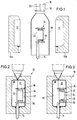
- a device for carrying out the method according to the invention can have a generally two-part blow mold 10 which is assigned a mandrel 14 which projects into the mold cavity 12 from below between the two blow mold halves 10a, 10b.
- the device also has an extrusion device with an extrusion head 16, which is provided with an annular outlet opening for the thermoplastic material when producing a tubular preform.
- This annular outlet opening is delimited on the inside by a core 18 which is provided with a channel 20 which is open at the bottom for a gaseous medium.
- the mandrel 14 can be provided with axial channels, not shown in the drawing, which, for. B. are arranged coaxially with each other, of which one channel is used to supply a pressure medium and the other channel is used to supply the reaction gas.
- axial channels not shown in the drawing, which, for. B. are arranged coaxially with each other, of which one channel is used to supply a pressure medium and the other channel is used to supply the reaction gas.
- the mandrel 14 is provided at its end projecting into the blow mold with a rod-like extension 22, which, however, has a noticeably smaller diameter than the mandrel 14.
- This extension 22 is arranged eccentrically on the mandrel 14, running parallel to it, so that a Rotation of the rotatably mounted mandrel 14 about its longitudinal axis a corresponding pivoting of the extension 22 about the longitudinal axis of the mandrel 14 results.
- the extension 22 serves during the manufacture of a product as a supporting element for a holder 24 which in turn carries an additional body 26 which is to be attached to the hollow body to be produced in the blow mold 10.
- the work cycle for producing a hollow body begins with the blow mold open (FIG. 1) with the mounting of the holder 24 on the rod-like extension 22 serving as a supporting element, which will be described in detail, the parts initially occupying the position shown in FIG. 1. That is to say that the mandrel 14 has previously been rotated into a position in which the rod-like support element 22 is located in the left vertex of the circular path, as is shown in FIGS. 1-3, which it rotates when the mandrel 14 is rotated would describe 180 °.
- a preform 28 is now extruded between the latter and is open at its lower end.
- the preform 28 is tubular. However, it can also be designed in a different way, for example consist of a band which is approximately U-shaped in cross section, or also consist of two bands which are connected to one another when the blow mold 10 is closed.
- Fig. 1 shows that the preform 28 has a diameter that allows it to be guided during the extrusion process relatively over the bracket 24 carried by the extension 22 with additional body 26.
- a gas is normally introduced into the preform through the channel 20, through which the preform 28 can undergo some pre-expansion, although the overpressure present in the preform 28 is small due to the fact that the preform is open at the bottom.
- the blow mold 10 is closed by correspondingly moving the two blow mold halves 10a, 10b from the positions according to FIG. 1 into those according to FIGS. 2 and 3.
- the preform 28 is squeezed at its upper end by the two blow mold halves 10a, 10b from the material still hanging on the extrusion head 16 and closed in the process. At the lower end, the preform is pressed around the mandrel 14, possibly with excess material squeezed off.
- inert gas is first introduced through one of the channels in the mandrel 14 under pressure into the possibly pre-expanded preform 16, with the result that the preform is brought to bear on the wall of the mold cavity 12 everywhere and thus takes on its shape, which essentially corresponds to the shape of the hollow body 30 to be produced.
- Fig. 2 of the drawing shows that due to the selected position of the mandrel 14 in the circumferential direction, the holder 24 and thus the additional body 26 carried by it in this process stage at a distance of - based on the representations of FIGS. 2 and 3 - right Are wall area 32 of the hollow body 30 to which the additional body 26 is to be attached.
- the distance between the bottom 34 of the cup-shaped additional body 26 and the wall area 32 is so large that a treatment medium located within the hollow body 30 has unimpeded access to this wall area 32 at all times.
- the distance of the additional body 26 from the other wall areas is so great that a medium flowing inside the hollow body 30 has unrestricted access everywhere.
- the Mandrel 14 rotated by 180 ° about its longitudinal axis. This results in a corresponding pivoting of the rod-like extension 22 serving as a supporting element for the holder 24 and the additional body 26, with the result that, in the course of this pivoting movement, the holder 24 with the additional body 26 moves from the position according to FIG. 2 into that according to FIG is shifted to the right.
- the eccentricity of the extension 22 with respect to the mandrel 14 is chosen such that at the end of the pivoting movement the widened foot parts 36 of the holder 24 facing the wall region 32 come into contact with the wall region 32 under a certain pressure and thus form a firm connection between the holder 24 and wall area 32 are welded.
- FIG. 3 This position of the latter which brings about the fixed connection between the wall region 32 and the holder 24 is shown in FIG. 3. Since the holder 24 with the additional body 26 should always assume positions during the pivoting movement carried out by the extension 22, which run parallel to a plane which is defined by the starting position of the holder 24 and additional body 26 shown in FIG. 2, the rod-like extension 22 about its longitudinal axis relative to the mandrel 14 rotatably mounted in the latter, means not shown being provided in the drawing, which fix the angular position of the extension 22 with respect to its longitudinal axis.
- the treatment medium is then blown into the hollow body 30 via the mandrel 14 or another feed, which leads to the already mentioned implementation of the inner surface of the wall leads.
- Fig. 3 of the drawing shows that the additional body 26 is on all sides so far from the wall of the hollow body 30 that the treatment gas to all wall areas, in particular also to the wall area 32, which is opposite the bottom 34 of the additional body 26, unimpeded access Has.
- the additional body 26 designed as a swirl pot is then moved from the position according to FIG. 3 to the position according to FIG. 5, in which the bottom 34 of the swirl pot rests in the region 32 against the wall of the hollow body. This can be done inside or outside the blow mold.
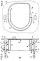
- FIGS. 4-6 show details of the design of the holder 24 and the additional body 26.
- the latter has the already mentioned bottom 34 and side walls 38 and internals located within the pot, which, however, are of no importance for the invention and depend on the respective requirements and circumstances .
- the additional body 26 is provided with two extensions 40, 41, which run approximately parallel to the bottom 34 and the wall area 32 and have openings 42.
- the extensions 40, 41 with the openings 42 serve as guide means for the additional body 26 on the holder 24, which essentially consists of two stands 44, 45, which run essentially perpendicular to the wall region 32 of the hollow body 30.
- the stands 44, 45 have, as can be seen in particular in FIG. 6, an essentially rectangular cross section.
- they are provided with foot-like widenings 36.
- the boundary surfaces of the widened, approximately plate-shaped foot parts 36 facing the wall area 32 become at the end of the above-described movement of the parts from the position according to FIG. 2 into that of FIG. 3 against the still hot one and thus pressed plastic inner boundary surface of the wall area 32 for the purpose of producing a welded connection.
- each stand 44, 45 facing away from the foot-like widening 36, an opening 48 or 49 is provided, of which the opening 48 is circular in cross-section and is likewise adapted to the extension 22 which is circular in cross-section over most of its longitudinal extent.
- the end section 50 of the rod-like extension 22, however, has a positive, here square cross-section, to which the opening 49 in the stand 45 is adapted. This square cross section of the opening 49 and the end section 50 brings about a positive connection which prevents a pivoting movement of the holder 24 consisting of the two stands 44, 45 about the longitudinal axis of the extension 22.
- the holder 24 is first connected to the additional body 26 in such a way that the two stands 44, 45 are inserted through the holes 42 in the associated appendages 40, 41, in such a way that the parts in FIGS. assume the relative position shown to each other. Thereafter, the unit consisting of the holder 24 and the additional body 26 is plugged onto the rod-like extension 22 serving as the supporting element, so that the result is the position of the parts shown in FIGS. 1 and 2.
- the stand 45 is provided at the level of the extension 41 located near the bottom 34 with small, rounded projections 51, 52 which, in the position of the parts according to FIGS. 2-4, have an extension 41 between them record and secure it against displacement relative to the stand 45 as long as no excessive force, which is directed accordingly, acts on the stand 45 and / or additional body 26.
- the stand 45 will normally be made of thermoplastic, this is the knob-like one Projections 51, 52, which are integral with the stand 45, forming material elastically deformable, so that in particular when the extension 41 is made of plastic, the stand 45 with the projections 51, 52 can be guided through the hole in the extension 41 , wherein only a somewhat greater force is to be applied in order to overcome the resistance caused by the projections 51 with corresponding deformation of the projections 51 and / or the extension 41.
- the expansion elements 60 serving as locking means for the additional body.
- the extension 22 serving as a supporting element can be made by a corresponding axial movement the two stands 44, 45 of the holder 24 are retracted in the direction of the arrow 54.
- the additional body 26 is moved in the direction of arrow 56 from the position shown in FIGS. 3 and 4 to the position according to FIG. 5, in which the bottom 34 of the additional body lies more or less closely against the wall area 32.
- a force is again to be applied which is sufficient to overcome the resistance of the projections 52 and the locking elements 60 on the stand 45.
- FIGS. 1-6 other means can also be provided to secure the additional body in its respective position on the stands 44, 45. If necessary, this can also be done via frictional forces, the cross-sectional dimensions of at least one of the two stands 44, 45 then corresponding to the dimensions of the holes 42 in the extensions 40, 41 serving as guide means would have to be adapted.
- the projections 60 can also be integrally formed on the uprights 44, 45, for example in the injection molding process. The same applies to the projections 51, 52.
- the holder 24 is in two pieces, since it consists of the two stands 44, 45, which are connected independently of each other to the additional body 26 and are located outside of the same.
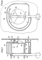
- the holder 124 is provided with a star-shaped foot part 136, on the latter a plate 162 is attached to the rod-shaped support element 122 facing side, which is supported by the two stands 144, 145. The latter are designed in the manner already described and can be plugged onto the support element 122.
- the holder 124 is provided with a star-shaped foot part 136, on the latter a plate 162 is attached to the rod-shaped support element 122 facing side, which is supported by the two stands 144, 145. The latter are designed in the manner already described and can be plugged onto the support element 122.
- the two stands 144, 145 are located within the additional body 126. Accordingly, there is a need to provide the bottom 134 of the additional body 126 designed as a surge pot with an opening 135 which corresponds to the star-shaped configuration of the foot part 136 is also advantageously star-shaped.
- the advantage of this star-shaped configuration is that the contact surfaces (cf. contact surfaces 266 in FIG.
- the projections 151, 152 on the foot part 136 also have the function of securing the additional body 126 in its first position on the holder 124 against unintentional displacement.
- the same also applies to the projections 160 which, when the holder 124 and the additional body 126 are assembled, may first be brought into a position which allows the foot part 136 to be guided through the opening 135 located in the bottom 134 of the additional body 126.
- the boundaries of the star-shaped opening 135 located in the bottom 134 form the guide means during the displacement of the additional body 126 from its first position shown in FIG. 7 of the drawing to its second position.
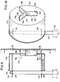
- FIGS. 9 and 10 show a third embodiment in which parts corresponding to embodiment 1-6 are provided with the same, but 200 higher reference numerals.
- the holder 224 to be connected to the wall area 232 of the hollow body is star-shaped, so that only the narrow end faces 266 of the star are connected to the wall and cover only correspondingly small sections of the wall.
- the additional body 226 and the holder 224 are produced in one piece in the position shown in FIG. 9, for example in the injection molding process.
- the transition 264 of the bottom 234 of the additional body 226 to the holder 224 penetrating the bottom is designed as a predetermined breaking point.
- the latter comes into operation if, after the treatment of the inner surface 232, the additional body is brought into its second position on or near the wall with a corresponding effort.
- the predetermined breaking point is designed and dimensioned such that a force must be exerted in order to bring about the breaking, which force is greater than the force required for proper welding of the foot part 236 to the wall 232 is required. Since in this embodiment the holder 224 is held by the additional body 226, as long as the unit consisting of the holder 224 and the additional body 226 is held by the extension 222 serving as a supporting element, the additional body 226 is provided with extensions 240, 241, on which openings 248 or 249 are attached for the passage of the rod-like support element 222.
- Figure 9 of the drawing shows the parts in positions corresponding to those of Figure 3.
- the foot part 236 of the holder 224 is pressed against the wall region 332 by a corresponding rotation of the mandrel 214, which leads to a corresponding pivoting of the support element 222 and thus to the necessary displacement of the holder 224 and additional body 226 existing unit leads.
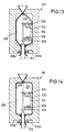
- the process sequence in the exemplary embodiment according to FIGS. 11-14 essentially corresponds to the process sequence in the exemplary embodiments described above, so that identical parts are also provided with the same, but 300 higher reference numerals than the reference symbols of the exemplary embodiment according to FIGS. 1-3 .
- the mandrel 314 which is also provided with channels (not shown in the drawing) for the supply of a pressure medium or the supply of the reaction gas, carries a rod-like extension 322 which can be arranged centrally.
- the extension 322 does not have to perform a pivoting movement about the longitudinal axis of the mandrel 314 in order to connect the holder 324 and the additional body 326 carried by it to the wall of the hollow body. Rather, the connection between the holder 324 and the wall of the hollow body is brought about by the closing movement of the blow molded part 310b.
- the extension 322 is arranged such that the holder 324 assumes a position in which the foot parts 336 come into contact with the wall of the hollow body 330 at least in the final phase of the closing movement of the Blaformteil 310b and are pressed so firmly against the wall that a sufficiently firm connection is established.
- the blow mold parts 310a, 310b are different since the blow mold 310 is not divided in half.
- a further difference compared to the device according to FIGS. 1-3 is that additionally clamping jaws 370a, 370b are provided in the lower area of the blow mold 310, of which the clamping jaw 370a is assigned to the blow molding part 310a and the clamping jaw 370b to the blow molding part 310b.
- Both clamping jaws 370a, 370b can be moved independently of the blow molded parts 310a, 310b.
- the drive means for the clamping jaws are not shown in the drawing for reasons of clarity.
- the device of the exemplary embodiment according to FIGS. 11-14 is provided with an additional transport means 316, by means of which the preform 328 is removed from the extrusion head, not shown in FIGS. 11-14, held and transported into the open blow mold 310.
- Such an additional means of transport is such.
- Such transport and holding means for the preform are state of the art. For example, they can be designed as grippers, but also in a different way. Since its design has nothing to do with the present invention, the means of transport 316 is only indicated in the drawing.
- FIG. 12 A first phase of this expansion process is shown in FIG. 12.
- the wall area 332 is pressed by the wall of the blow-molded part 310b against the foot parts 336 of the holder 324 carried by the mandrel 314 which is not moved in the process, the pressure being sufficient for the subsequent solidification of the part which forms the hollow body Material to bring about a permanent weld between the foot parts 336 of the bracket 324 and the wall portion 332 of the hollow body.
- the process stage at which the foot parts 336 are in contact with the wall area 332 is shown in FIG.
- the blow mold 310 is completely closed.
- the expansion of the preform 328 to the hollow body 330 has already been largely completed at this point in time, so that in the following process section only the two end regions of the preform located up and down to the system are to be expanded on the blow mold.
- the preform 328 already begins to expand before the blow mold 310 is completely closed, the preform is more likely to be deformed, since the preform may be expanded more than at least in some areas before the blow mold is finally closed this corresponds to the cross-sectional shape of the finished hollow body 330, so that by closing the blow molded parts the preform 328 may even experience a cross-sectional narrowing in its central region.
- the establishment of the connection between the holder 324 and the wall of the hollow body 330 presupposes that the wall region 332, that is to say the wall region on which the connection to the holder 324 is made, on the wall of the blow mold 310, that is to say, more precisely abuts the wall of the blow molded part 310b, the closing movement of which exerts the pressure for establishing the connection between the holder and the hollow body wall.
- the additional body 326 is moved into the position according to FIG. 5 in the manner already described in connection with the other exemplary embodiments.
- the additional material required for the mounting is negligible.
- the fact that the holder remains in addition to the additional body in the hollow body after its completion is not a disadvantage.
- the surface treatment can also be carried out by sulfonation.
Landscapes
- Engineering & Computer Science (AREA)
- Mechanical Engineering (AREA)
- Manufacturing & Machinery (AREA)
- Life Sciences & Earth Sciences (AREA)
- Sustainable Development (AREA)
- Sustainable Energy (AREA)
- Chemical & Material Sciences (AREA)
- Combustion & Propulsion (AREA)
- Transportation (AREA)
- Blow-Moulding Or Thermoforming Of Plastics Or The Like (AREA)
- Moulds For Moulding Plastics Or The Like (AREA)
- Processing And Handling Of Plastics And Other Materials For Molding In General (AREA)
Applications Claiming Priority (2)
| Application Number | Priority Date | Filing Date | Title |
|---|---|---|---|
| DE4203705 | 1992-02-08 | ||
| DE4203705A DE4203705A1 (de) | 1992-02-08 | 1992-02-08 | Verfahren zum herstellen von hohlkoerpern aus thermoplastischem kunststoff sowie hohlkoerper aus thermoplastischem kunststoff |
Publications (2)
| Publication Number | Publication Date |
|---|---|
| EP0556552A1 EP0556552A1 (de) | 1993-08-25 |
| EP0556552B1 true EP0556552B1 (de) | 1997-03-19 |
Family
ID=6451262
Family Applications (1)
| Application Number | Title | Priority Date | Filing Date |
|---|---|---|---|
| EP93100355A Expired - Lifetime EP0556552B1 (de) | 1992-02-08 | 1993-01-13 | Verfahren zum Herstellen von Hohlkörpern aus thermoplastischem Kunststoff sowie Hohlkörper aus thermoplastischem Kunststoff |
Country Status (6)
| Country | Link |
|---|---|
| US (1) | US5326514A (es) |
| EP (1) | EP0556552B1 (es) |
| CA (1) | CA2088953C (es) |
| CZ (1) | CZ287869B6 (es) |
| DE (2) | DE4203705A1 (es) |
| ES (1) | ES2100371T3 (es) |
Families Citing this family (41)
| Publication number | Priority date | Publication date | Assignee | Title |
|---|---|---|---|---|
| BE1006435A3 (fr) * | 1992-12-07 | 1994-08-23 | Solvay | Procede et dispositif pour le moulage par soufflage de corps creux en matiere thermoplastique. |
| DE19600872A1 (de) * | 1996-01-12 | 1997-07-17 | Bosch Gmbh Robert | Kraftstoffbehälter mit darin angeordneter Kraftstoffördereinrichtung und Verfahren zu dessen Herstellung |
| US5931353A (en) * | 1997-04-28 | 1999-08-03 | Solvay (Societe Anonyme) | Plastic hollow body with internal fastening arrangement |
| FR2771683B1 (fr) * | 1997-12-02 | 2000-02-04 | Solvay | Reservoir a carburant |
| US6626325B1 (en) * | 1998-11-13 | 2003-09-30 | Hoover Materials Handling Group Inc. | Blow molding appurtenances to a container |
| BE1013191A3 (fr) | 1999-12-22 | 2001-10-02 | Solvay | Procede de fabrication de corps creux en matiere plastique. |
| US6712234B2 (en) * | 2000-02-14 | 2004-03-30 | Ti Group Automotive Systems Technology Center Gmbh | Fuel tank and method for its production |
| FR2806959B1 (fr) * | 2000-04-03 | 2003-02-14 | Plastic Omnium Cie | Procede de fabrication d'un reservoir en matiere thermoplastique soufflee incorporant un insert |
| EP1309436A2 (en) * | 2000-08-11 | 2003-05-14 | Visteon Global Technologies, Inc. | Adapter for welding objects to plastic |
| US6978802B2 (en) * | 2001-03-08 | 2005-12-27 | Toyoda Gosei Co., Ltd. | Fuel tank and manufacturing method thereof |
| US20030136507A1 (en) * | 2002-01-18 | 2003-07-24 | Thiel Steven A. | Thermoformed fuel tank fuel delivery system and assembly method |
| US6959696B2 (en) * | 2002-04-12 | 2005-11-01 | Briggs & Stratton Corporation | Internal combustion engine evaporative emission control system |
| DE10260953B4 (de) * | 2002-12-20 | 2010-07-01 | Kautex Textron Gmbh & Co Kg | Kraftstoffbehälter mit Funktionsbauteil-Träger sowie Träger für Funktionsbauteile eines KFZ-Kraftstoffbehälters |
| FR2873321B1 (fr) * | 2004-07-23 | 2008-05-09 | Inergy Automotive Systems Res | Procede pour la fixation d'un accessoire dans un reservoir a carburant en matiere plastique |
| FR2875430B1 (fr) | 2004-09-23 | 2006-12-08 | Inergy Automotive Systems Res | Procede pour la fixation d'une embase sur la paroi d'un reservoir a carburant |
| US7185640B2 (en) | 2004-11-05 | 2007-03-06 | Briggs & Stratton Corporation | Integrated fuel tank and vapor containment system |
| US7086390B2 (en) * | 2004-11-05 | 2006-08-08 | Briggs & Stratton Corporation | Integrated fuel tank and vapor containment system |
| US7435289B2 (en) * | 2005-09-27 | 2008-10-14 | Briggs & Stratton Corporation | Integrated air cleaner and vapor containment system |
| DE102005056860A1 (de) * | 2005-11-29 | 2007-05-31 | GM Global Technology Operations, Inc., Detroit | Kraftstoffbehälter |
| WO2007088200A1 (en) * | 2006-02-03 | 2007-08-09 | Inergy Automotive Systems Research (Société Anonyme) | Process and equipment for manufacturing a fuel tank provided with internal accessories |
| US7281525B2 (en) * | 2006-02-27 | 2007-10-16 | Briggs & Stratton Corporation | Filter canister family |
| DE102006027255A1 (de) * | 2006-06-09 | 2007-12-13 | Kautex Textron Gmbh & Co. Kg | Verfahren zur Herstellung von Hohlkörpern aus thermoplastischem Kunststoff |
| US7922949B2 (en) * | 2006-07-07 | 2011-04-12 | Kautex Textron Gmbh & Co. Kg | Procedure for producing hollow bodies of thermoplastic material |
| FR2915923B1 (fr) | 2007-05-10 | 2009-07-10 | Inergy Automotive Systems Res | Procede de fabrication d'un reservoir a carburant muni d'un accessoire interne |
| JP5270911B2 (ja) * | 2007-11-30 | 2013-08-21 | 株式会社Fts | 自動車用燃料タンク |
| JP5078012B2 (ja) * | 2007-12-21 | 2012-11-21 | 株式会社Fts | 自動車用燃料タンクの製造装置 |
| DE102008029168A1 (de) * | 2008-06-19 | 2009-12-24 | Beiersdorf Ag | Behältnis mit innenliegendem funktionalem Element |
| FR2934804A1 (fr) * | 2008-08-07 | 2010-02-12 | Inergy Automotive Systems Res | Procede pour la fabrication d'un reservoir a carburant en matiere plastique. |
| US9085229B2 (en) * | 2008-11-11 | 2015-07-21 | Ti Group Automotive Systems, L.L.C. | Fuel tank assemblies, components, and methods of manufacture |
| DE102009030492B4 (de) * | 2009-06-24 | 2023-06-15 | Kautex Maschinenbau Gmbh | Verfahren zur Herstellung eines Kunststoffartikels sowie Blasformwerkzeug |
| DE102009031441B4 (de) | 2009-07-01 | 2012-06-28 | Kautex Maschinenbau Gmbh | Verfahren zur Herstellung eines Artikels aus thermoplastischem Kunststoff |
| US9050889B2 (en) | 2009-09-18 | 2015-06-09 | Ti Automotive Technology Center Gmbh | Fuel tank support |
| JP5097221B2 (ja) * | 2010-01-19 | 2012-12-12 | 八千代工業株式会社 | 樹脂製燃料タンクの部品固定構造 |
| JP5495873B2 (ja) * | 2010-03-16 | 2014-05-21 | 株式会社Fts | 自動車用燃料タンク |
| FR2961738B1 (fr) * | 2010-06-23 | 2014-02-28 | Inergy Automotive Systems Res | Procede de fabrication d'un reservoir a carburant muni d'un baffle |
| DE102010025006A1 (de) | 2010-06-24 | 2011-12-29 | Kautex Textron Gmbh & Co. Kg | Verfahren zur Herstellung von Hohlkörpern aus thermoplastischem Kunststoff sowie Vorrichtung zur Durchführung des Verfahrens |
| DE102010025937A1 (de) * | 2010-07-02 | 2012-01-05 | Kautex Maschinenbau Gmbh | Verfahren zur Herstellung eines Kunststoffartikels sowie Blasformwerkzeug zur Durchführung des Verfahrens |
| DE102010032279B4 (de) * | 2010-07-26 | 2012-09-06 | Kautex Textron Gmbh & Co. Kg | Verfahren zur Nietbefestigung eines Zubehörteils |
| WO2012075355A1 (en) | 2010-12-03 | 2012-06-07 | Salflex Polymers Limited | Deployable fuel tank baffle and fuel tank system |
| WO2014122747A1 (ja) * | 2013-02-07 | 2014-08-14 | 株式会社Fts | 自動車用燃料タンク |
| EP2857245A1 (en) | 2013-10-03 | 2015-04-08 | Inergy Automotive Systems Research (Société Anonyme) | Tank with internal connecting member and method for assembling such a tank |
Family Cites Families (10)
| Publication number | Priority date | Publication date | Assignee | Title |
|---|---|---|---|---|
| US3954369A (en) * | 1969-09-16 | 1976-05-04 | Elbatainer Kunststoff- Und Verpackungs-Gesellschaft Mbh & Co. | Apparatus for making a liquid container from thermoplastic synthetic material |
| US4396562A (en) * | 1978-07-28 | 1983-08-02 | Creaplast | Method of producing a hollow monobloc body by using a blowing process |
| DE2936318B2 (de) * | 1979-08-09 | 1981-07-16 | Volkswagenwerk Ag, 3180 Wolfsburg | Behälter, insbesondere Kraftstoffbehälter für Kraftfahrzeuge |
| JPS5675832A (en) * | 1979-11-22 | 1981-06-23 | Showa Denko Kk | Preparation of hollow molding |
| DE3042926C2 (de) * | 1980-11-14 | 1984-06-20 | Elbatainer Kunststoff- Und Verpackungsgesellschaft Mbh, 7505 Ettlingen | Verfahren und Vorrichtung zur Herstellung eines Kraftstofftanks |
| FI811938L (fi) * | 1981-06-22 | 1982-12-23 | Pyrkijae Oy | Foerfarande foer infaestande av en separat extra tank i en tank av plast i dess framstaellningsskede |
| JPS60234823A (ja) * | 1984-05-08 | 1985-11-21 | Ishikawajima Harima Heavy Ind Co Ltd | ブロ−成形における内部インサ−トの装着方法 |
| DE3435592A1 (de) * | 1984-09-28 | 1986-04-03 | Kautex Werke Reinold Hagen AG, 5300 Bonn | Verfahren zur herstellung von hohlkoerpern aus thermoplastischem kunststoff |
| JPS61225027A (ja) * | 1985-03-30 | 1986-10-06 | Yamakawa Kogyo Kk | 合成樹脂製燃料タンクにおける別体部品の取付方法 |
| JPH0491923A (ja) * | 1990-08-07 | 1992-03-25 | Araki Kanagata Seisakusho:Kk | ブロー成形品の製造方法、及びその方法に使用する成形型装置 |
-
1992
- 1992-02-08 DE DE4203705A patent/DE4203705A1/de not_active Withdrawn
-
1993
- 1993-01-13 DE DE59305825T patent/DE59305825D1/de not_active Expired - Lifetime
- 1993-01-13 EP EP93100355A patent/EP0556552B1/de not_active Expired - Lifetime
- 1993-01-13 ES ES93100355T patent/ES2100371T3/es not_active Expired - Lifetime
- 1993-02-04 CZ CZ1993135A patent/CZ287869B6/cs not_active IP Right Cessation
- 1993-02-04 US US08/013,596 patent/US5326514A/en not_active Expired - Fee Related
- 1993-02-05 CA CA002088953A patent/CA2088953C/en not_active Expired - Fee Related
Also Published As
| Publication number | Publication date |
|---|---|
| US5326514A (en) | 1994-07-05 |
| CZ287869B6 (en) | 2001-02-14 |
| EP0556552A1 (de) | 1993-08-25 |
| DE59305825D1 (de) | 1997-04-24 |
| DE4203705A1 (de) | 1993-08-12 |
| ES2100371T3 (es) | 1997-06-16 |
| CA2088953A1 (en) | 1993-08-09 |
| CZ13593A3 (en) | 1993-12-15 |
| CA2088953C (en) | 1996-10-22 |
Similar Documents
| Publication | Publication Date | Title |
|---|---|---|
| EP0556552B1 (de) | Verfahren zum Herstellen von Hohlkörpern aus thermoplastischem Kunststoff sowie Hohlkörper aus thermoplastischem Kunststoff | |
| DE60010070T2 (de) | Methode zur herstellung von laminierten flaschen mit abschälbarer innerer schicht | |
| DE69110819T2 (de) | Spritzgiesssystem zum Herstellen einer hinterschnittenen Vorformung. | |
| DE3587856T2 (de) | Hohlkörper und Verfahren und Vorrichtung zu dessen Herstellung. | |
| DE2831990A1 (de) | Verfahren zur herstellung eines flexiblen, zusammenfaltbaren behaelters und nach diesem verfahren hergestellter behaelter | |
| DE68927578T2 (de) | Verfahren und Vorrichtung zum Blasformen | |
| DE1604653B2 (de) | Hohlkoerper aus kunststoff sowie verfahren und vorrichtung zu dessen herstellung | |
| DE69103856T2 (de) | Vorrichtung zur Herstellung von Zellen in fortlaufenden Bäudern, vorzugsweise zum Verpacken von Suppositorien od.dgl. | |
| WO2007140880A1 (de) | Verfahren zur herstellung von hohlkörpern aus thermoplastischem kunststoff durch extrusionsblasformen mit kontinuierlicher düsenspaltverstellung | |
| DE69122589T2 (de) | Vorform zum Formen eines Behälters mit Aufhänger und Verfahren zum Formen eines solchen Behälters | |
| DE3028769A1 (de) | Verfahren und vorrichtung zur anbringung einer kunststoff-bodenplatte am einen ende eines kunststoff-hohlzylinders | |
| DE69200315T2 (de) | Vorrichtung und Verfahren zum Wieder-im-Form-bringen von Behältern. | |
| DE60122000T2 (de) | Verfahren und formvorrichtung zum verformen eines hohlen werkstücks | |
| DE1454955A1 (de) | Verfahren zur Herstellung von Behaeltern und Vorrichtung zur Durchfuehrung des Verfahrens | |
| DE69027604T2 (de) | Verfahren und vorrichtung zur herstellung eines zusammengebauten gegenstandes | |
| DE1178580B (de) | Verfahren und Vorrichtung zum Herstellen von Hohlkoerpern aus thermoplastischem Kunststoff | |
| EP0867374A1 (de) | Verfahren zur Herstellung einer Mehrkammer-Verpackungstube | |
| DE102008044640A1 (de) | Verfahren zum Herstellen eines Hohlkörpers aus Kunststoff, Vorrichtung und Gerät zu dessen Umsetzen | |
| DE2454134A1 (de) | Blasform- und streckverfahren zur herstellung von hohlen kunststoffartikeln und vorrichtung zur durchfuehrung des verfahrens | |
| EP0955152B1 (de) | Verfahren zur Herstellung einer Mehrkammer-Verpackungstube | |
| EP0228616A2 (de) | Verfahren und Vorrichtung zum Herstellen von Hohlkörpern aus thermoplastischen Kunststoffen | |
| DE2116677A1 (en) | Plastic closure - prepd by moulding in cavity between three part press plug and die | |
| DE2952797C1 (es) | ||
| DE69628164T2 (de) | Verfahren zur Herstellung von spritzgegossenen Gegenständen, Vorrichtung zur Durchführung dieses Verfahrens und neue geformte Gegenstände | |
| DE60023741T2 (de) | Verfahren zum überspritzen von röhren in kunststoffteilen |
Legal Events
| Date | Code | Title | Description |
|---|---|---|---|
| PUAI | Public reference made under article 153(3) epc to a published international application that has entered the european phase |
Free format text: ORIGINAL CODE: 0009012 |
|
| AK | Designated contracting states |
Kind code of ref document: A1 Designated state(s): BE DE ES FR GB IT NL PT SE |
|
| 17P | Request for examination filed |
Effective date: 19931229 |
|
| 17Q | First examination report despatched |
Effective date: 19950411 |
|
| GRAG | Despatch of communication of intention to grant |
Free format text: ORIGINAL CODE: EPIDOS AGRA |
|
| GRAH | Despatch of communication of intention to grant a patent |
Free format text: ORIGINAL CODE: EPIDOS IGRA |
|
| GRAH | Despatch of communication of intention to grant a patent |
Free format text: ORIGINAL CODE: EPIDOS IGRA |
|
| ITF | It: translation for a ep patent filed | ||
| GRAA | (expected) grant |
Free format text: ORIGINAL CODE: 0009210 |
|
| AK | Designated contracting states |
Kind code of ref document: B1 Designated state(s): BE DE ES FR GB IT NL PT SE |
|
| GBT | Gb: translation of ep patent filed (gb section 77(6)(a)/1977) |
Effective date: 19970319 |
|
| REF | Corresponds to: |
Ref document number: 59305825 Country of ref document: DE Date of ref document: 19970424 |
|
| REG | Reference to a national code |
Ref country code: ES Ref legal event code: FG2A Ref document number: 2100371 Country of ref document: ES Kind code of ref document: T3 |
|
| REG | Reference to a national code |
Ref country code: PT Ref legal event code: SC4A Free format text: AVAILABILITY OF NATIONAL TRANSLATION Effective date: 19970319 |
|
| ET | Fr: translation filed | ||
| PLBE | No opposition filed within time limit |
Free format text: ORIGINAL CODE: 0009261 |
|
| STAA | Information on the status of an ep patent application or granted ep patent |
Free format text: STATUS: NO OPPOSITION FILED WITHIN TIME LIMIT |
|
| 26N | No opposition filed | ||
| PGFP | Annual fee paid to national office [announced via postgrant information from national office to epo] |
Ref country code: PT Payment date: 20001205 Year of fee payment: 9 |
|
| PGFP | Annual fee paid to national office [announced via postgrant information from national office to epo] |
Ref country code: NL Payment date: 20010131 Year of fee payment: 9 |
|
| REG | Reference to a national code |
Ref country code: GB Ref legal event code: IF02 |
|
| PG25 | Lapsed in a contracting state [announced via postgrant information from national office to epo] |
Ref country code: PT Free format text: LAPSE BECAUSE OF NON-PAYMENT OF DUE FEES Effective date: 20020731 |
|
| PG25 | Lapsed in a contracting state [announced via postgrant information from national office to epo] |
Ref country code: NL Free format text: LAPSE BECAUSE OF NON-PAYMENT OF DUE FEES Effective date: 20020801 |
|
| NLV4 | Nl: lapsed or anulled due to non-payment of the annual fee |
Effective date: 20020801 |
|
| REG | Reference to a national code |
Ref country code: PT Ref legal event code: MM4A Free format text: LAPSE DUE TO NON-PAYMENT OF FEES Effective date: 20020731 |
|
| PGFP | Annual fee paid to national office [announced via postgrant information from national office to epo] |
Ref country code: SE Payment date: 20030117 Year of fee payment: 11 |
|
| PG25 | Lapsed in a contracting state [announced via postgrant information from national office to epo] |
Ref country code: SE Free format text: LAPSE BECAUSE OF NON-PAYMENT OF DUE FEES Effective date: 20040114 |
|
| EUG | Se: european patent has lapsed | ||
| PGFP | Annual fee paid to national office [announced via postgrant information from national office to epo] |
Ref country code: IT Payment date: 20060131 Year of fee payment: 14 |
|
| PGFP | Annual fee paid to national office [announced via postgrant information from national office to epo] |
Ref country code: GB Payment date: 20090122 Year of fee payment: 17 |
|
| PG25 | Lapsed in a contracting state [announced via postgrant information from national office to epo] |
Ref country code: IT Free format text: LAPSE BECAUSE OF NON-PAYMENT OF DUE FEES Effective date: 20070113 |
|
| PGFP | Annual fee paid to national office [announced via postgrant information from national office to epo] |
Ref country code: ES Payment date: 20100125 Year of fee payment: 18 |
|
| PGFP | Annual fee paid to national office [announced via postgrant information from national office to epo] |
Ref country code: FR Payment date: 20100223 Year of fee payment: 18 |
|
| PGFP | Annual fee paid to national office [announced via postgrant information from national office to epo] |
Ref country code: DE Payment date: 20091224 Year of fee payment: 18 |
|
| PGFP | Annual fee paid to national office [announced via postgrant information from national office to epo] |
Ref country code: BE Payment date: 20100315 Year of fee payment: 18 |
|
| GBPC | Gb: european patent ceased through non-payment of renewal fee |
Effective date: 20100113 |
|
| PG25 | Lapsed in a contracting state [announced via postgrant information from national office to epo] |
Ref country code: GB Free format text: LAPSE BECAUSE OF NON-PAYMENT OF DUE FEES Effective date: 20100113 |
|
| BERE | Be: lapsed |
Owner name: *KAUTEX WERKE REINOLD HAGEN A.G. Effective date: 20110131 |
|
| REG | Reference to a national code |
Ref country code: FR Ref legal event code: ST Effective date: 20110930 |
|
| PG25 | Lapsed in a contracting state [announced via postgrant information from national office to epo] |
Ref country code: FR Free format text: LAPSE BECAUSE OF NON-PAYMENT OF DUE FEES Effective date: 20110131 |
|
| PG25 | Lapsed in a contracting state [announced via postgrant information from national office to epo] |
Ref country code: BE Free format text: LAPSE BECAUSE OF NON-PAYMENT OF DUE FEES Effective date: 20110131 |
|
| REG | Reference to a national code |
Ref country code: DE Ref legal event code: R119 Ref document number: 59305825 Country of ref document: DE Effective date: 20110802 |
|
| REG | Reference to a national code |
Ref country code: ES Ref legal event code: FD2A Effective date: 20120220 |
|
| PG25 | Lapsed in a contracting state [announced via postgrant information from national office to epo] |
Ref country code: ES Free format text: LAPSE BECAUSE OF NON-PAYMENT OF DUE FEES Effective date: 20110114 |
|
| PG25 | Lapsed in a contracting state [announced via postgrant information from national office to epo] |
Ref country code: DE Free format text: LAPSE BECAUSE OF NON-PAYMENT OF DUE FEES Effective date: 20110802 |