EP0955152B1 - Verfahren zur Herstellung einer Mehrkammer-Verpackungstube - Google Patents
Verfahren zur Herstellung einer Mehrkammer-Verpackungstube Download PDFInfo
- Publication number
- EP0955152B1 EP0955152B1 EP99810378A EP99810378A EP0955152B1 EP 0955152 B1 EP0955152 B1 EP 0955152B1 EP 99810378 A EP99810378 A EP 99810378A EP 99810378 A EP99810378 A EP 99810378A EP 0955152 B1 EP0955152 B1 EP 0955152B1
- Authority
- EP
- European Patent Office
- Prior art keywords
- tube
- head
- partition
- mandrel
- die
- Prior art date
- Legal status (The legal status is an assumption and is not a legal conclusion. Google has not performed a legal analysis and makes no representation as to the accuracy of the status listed.)
- Expired - Lifetime
Links
Images


Classifications
-
- B—PERFORMING OPERATIONS; TRANSPORTING
- B29—WORKING OF PLASTICS; WORKING OF SUBSTANCES IN A PLASTIC STATE IN GENERAL
- B29C—SHAPING OR JOINING OF PLASTICS; SHAPING OF MATERIAL IN A PLASTIC STATE, NOT OTHERWISE PROVIDED FOR; AFTER-TREATMENT OF THE SHAPED PRODUCTS, e.g. REPAIRING
- B29C43/00—Compression moulding, i.e. applying external pressure to flow the moulding material; Apparatus therefor
- B29C43/02—Compression moulding, i.e. applying external pressure to flow the moulding material; Apparatus therefor of articles of definite length, i.e. discrete articles
- B29C43/18—Compression moulding, i.e. applying external pressure to flow the moulding material; Apparatus therefor of articles of definite length, i.e. discrete articles incorporating preformed parts or layers, e.g. compression moulding around inserts or for coating articles
-
- B—PERFORMING OPERATIONS; TRANSPORTING
- B29—WORKING OF PLASTICS; WORKING OF SUBSTANCES IN A PLASTIC STATE IN GENERAL
- B29C—SHAPING OR JOINING OF PLASTICS; SHAPING OF MATERIAL IN A PLASTIC STATE, NOT OTHERWISE PROVIDED FOR; AFTER-TREATMENT OF THE SHAPED PRODUCTS, e.g. REPAIRING
- B29C31/00—Handling, e.g. feeding of the material to be shaped, storage of plastics material before moulding; Automation, i.e. automated handling lines in plastics processing plants, e.g. using manipulators or robots
- B29C31/002—Handling tubes, e.g. transferring between shaping stations, loading on mandrels
-
- B—PERFORMING OPERATIONS; TRANSPORTING
- B29—WORKING OF PLASTICS; WORKING OF SUBSTANCES IN A PLASTIC STATE IN GENERAL
- B29C—SHAPING OR JOINING OF PLASTICS; SHAPING OF MATERIAL IN A PLASTIC STATE, NOT OTHERWISE PROVIDED FOR; AFTER-TREATMENT OF THE SHAPED PRODUCTS, e.g. REPAIRING
- B29C43/00—Compression moulding, i.e. applying external pressure to flow the moulding material; Apparatus therefor
- B29C43/32—Component parts, details or accessories; Auxiliary operations
- B29C43/36—Moulds for making articles of definite length, i.e. discrete articles
- B29C43/42—Moulds for making articles of definite length, i.e. discrete articles for undercut articles
-
- B—PERFORMING OPERATIONS; TRANSPORTING
- B29—WORKING OF PLASTICS; WORKING OF SUBSTANCES IN A PLASTIC STATE IN GENERAL
- B29D—PRODUCING PARTICULAR ARTICLES FROM PLASTICS OR FROM SUBSTANCES IN A PLASTIC STATE
- B29D23/00—Producing tubular articles
- B29D23/20—Flexible squeeze tubes, e.g. for cosmetics
-
- B—PERFORMING OPERATIONS; TRANSPORTING
- B29—WORKING OF PLASTICS; WORKING OF SUBSTANCES IN A PLASTIC STATE IN GENERAL
- B29C—SHAPING OR JOINING OF PLASTICS; SHAPING OF MATERIAL IN A PLASTIC STATE, NOT OTHERWISE PROVIDED FOR; AFTER-TREATMENT OF THE SHAPED PRODUCTS, e.g. REPAIRING
- B29C43/00—Compression moulding, i.e. applying external pressure to flow the moulding material; Apparatus therefor
- B29C43/32—Component parts, details or accessories; Auxiliary operations
- B29C43/36—Moulds for making articles of definite length, i.e. discrete articles
- B29C43/361—Moulds for making articles of definite length, i.e. discrete articles with pressing members independently movable of the parts for opening or closing the mould, e.g. movable pistons
- B29C2043/3615—Forming elements, e.g. mandrels or rams or stampers or pistons or plungers or punching devices
-
- B—PERFORMING OPERATIONS; TRANSPORTING
- B29—WORKING OF PLASTICS; WORKING OF SUBSTANCES IN A PLASTIC STATE IN GENERAL
- B29L—INDEXING SCHEME ASSOCIATED WITH SUBCLASS B29C, RELATING TO PARTICULAR ARTICLES
- B29L2001/00—Articles provided with screw threads
-
- B—PERFORMING OPERATIONS; TRANSPORTING
- B29—WORKING OF PLASTICS; WORKING OF SUBSTANCES IN A PLASTIC STATE IN GENERAL
- B29L—INDEXING SCHEME ASSOCIATED WITH SUBCLASS B29C, RELATING TO PARTICULAR ARTICLES
- B29L2023/00—Tubular articles
- B29L2023/20—Flexible squeeze tubes, e.g. for cosmetics
-
- B—PERFORMING OPERATIONS; TRANSPORTING
- B29—WORKING OF PLASTICS; WORKING OF SUBSTANCES IN A PLASTIC STATE IN GENERAL
- B29L—INDEXING SCHEME ASSOCIATED WITH SUBCLASS B29C, RELATING TO PARTICULAR ARTICLES
- B29L2031/00—Other particular articles
- B29L2031/712—Containers; Packaging elements or accessories, Packages
-
- Y—GENERAL TAGGING OF NEW TECHNOLOGICAL DEVELOPMENTS; GENERAL TAGGING OF CROSS-SECTIONAL TECHNOLOGIES SPANNING OVER SEVERAL SECTIONS OF THE IPC; TECHNICAL SUBJECTS COVERED BY FORMER USPC CROSS-REFERENCE ART COLLECTIONS [XRACs] AND DIGESTS
- Y10—TECHNICAL SUBJECTS COVERED BY FORMER USPC
- Y10S—TECHNICAL SUBJECTS COVERED BY FORMER USPC CROSS-REFERENCE ART COLLECTIONS [XRACs] AND DIGESTS
- Y10S264/00—Plastic and nonmetallic article shaping or treating: processes
- Y10S264/41—Processes of molding collapsible tubes
Definitions
- the invention relates to a method for producing a multi-chamber packaging tube according to the preamble of the claim 1.
- Multi-chamber packaging tubes are tubes with at least one Partition wall included in them for receiving up to theirs Removal of packaging goods to be kept separately, e.g. components a commodity that is only used for association should arrive. Commodities of this type appear on the Field of technology, hygiene, cosmetics and pharmacy increased in the foreground.
- Methods for producing multi-chamber tubes are known. Basically, the known methods are of two types and in assembly processes and molding processes (forming process) distinguished. The difference in The procedure is that the assembly process involves using tubes Partitions are assembled from individual parts while in the forming process tube tube with partition or head with Partition (i.e. always at least two tube components) in formed and then, e.g. Tube and Partition with head or head and partition with tube, be united.
- An assembly method in which a prefabricated Tube tube with an equally prefabricated tube head is connected. Then a wrinkled, in its longitudinal and transverse direction resilient partition in the Tube tube inserted.
- the partition i.e. a their transverse sides connected to the tube head by gluing, while the other transverse side with the closing seam of the tube is united. Due to the transverse and / or The partition wall is tensioned by longitudinal spring forces with their long sides against the inside of the tube and if no gluing is provided on the inside of the tube head between the closing seam and the tube head.
- a well-known molding process is characterized by that initially formed a head with a partition and then the head designed in this way with a tube is united.
- the disadvantage of this method is the overall complex automation (GB PS 1,030,275 to Rosier).
- a molding method using is also known a die and a mandrel, in which the mandrel either with a pipe pre-assembled with a partition or is loaded individually with pipe and partition.
- This The process leaves the formation of the partition in the head to the Head forming process by injection molding and it melts the partition in the pipe to the partition in the head.
- This Connections have proven to be insufficiently resilient proven (DE 196 40 833 C1, AISA Automation Industrielle SA).
- the invention has the object Basically, a process for producing multi-chamber tubes too create that the disadvantages of the assembly and molding process avoids and this task is accomplished by means of a procedure solved the features of claim 1.
- the invention is based on one of the tube manufacturing methods mentioned common process step - loading one Domes with a tube - to complete or add the Loading a mandrel with a prefabricated partition.
- the Loading with a partition can be done much faster will be the introduction of a Partition into a tube or the connection in the molding process a preformed tube with e.g. a partition of the tube continuing to the head, whereby the inventive method with respect to Application to multi-chamber tubes per unit of time Single-chamber tubes comes very close, so with the procedure
- a multi-chamber tube is comparably economical how single-chamber tubes are to be manufactured.
- the procedure according to the invention can be carried out as long as one Die and a mandrel the determining technical means for Are performing the procedure.
- Matrix and mandrel act as a head-forming form, in the latter liquid plastic injected under pressure (injection molding) or a certain amount of plasticized plastic under pressure is formed into a head by the mandrel (Molds). Since the mandrel in both cases the tube and according to the invention carries the partition, the tube is at Formation process of the head associated with the latter as well as that partition protruding into the head, unless it were Precautions taken, the partition not with the connecting the forming head.
- the die does not act on the head with respect to the head form-forming, but rather as the holder and holder of one of them Contour essentially corresponding prefabricated head and Device for melting the edge of the head and / or one pipe end positioned on a mandrel for both connections.
- the die can be localized to the head and / or melt the pipe with the partition so that the pipe and, if desired, partition is connected to the head become.
- the matrix is in relation to the one according to the invention Procedure in its function not on a formative Process element limited, but this also extends on bracket and heating. The same applies to the cathedral, which at the molding process as a mounting and shaping element, the attachment method as a holder for tube tube and Partition works. In the sense of the invention and before this The background is the matrix and the dome for molding and Attachment method functional functional equivalents.
- the connection of the transverse side of a partition to the head can be done in different ways.
- the short side is poured in Short side, i.e. one edge strip each on the transverse side during the Formation of the head in the plasticized plastic (PE) formed.
- PE plasticized plastic
- an adhesive or mechanical Attachment are provided, e.g. in the form of a groove that the inner surface of the head runs along and into an edge section the short side can be inserted. Should the partition remain unconnected to the head when gating and molding means to provide the edge portions of the Transverse sides opposite the injected or plasticized Cover plastics.
- Means for this could be disks that the front surface of a dome with inserted partition, Cover edge sections and cut edges. Remain long sides the partitions are not connected to the inner surface, so they lie on the inner surface, against the latter pressure exercising on.
- This can be done by designing the partition, e.g. in cross section "S" -shaped and thus in the opening direction of the "S" shaped design resilient or due to memory effect Restoring forces, for example, rounded flanges along the Long sides of the existing like tubes of plastic Partitions are created.
- the connection of the long sides with The inner surface of a tube tube can be glued or welding, the latter using Heat and pressure.
- the plastic of the partition i.e. e.g. one of the flanges running along the long side and possibly a strip opposite the flange along the plasticized or melted inner surface of the tube and flange and strip pressed together.
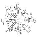
- Fig. 1 shows the rotary body designed as a rotary table 10 in the Top view.
- On the turntable 10 are in the circumferential direction in evenly spaced between dies 11 and mandrels 12, a mandrel 12 being associated with each die 11.
- the matrices 11 are open upwards and the domes 12 are made of one horizontal position at an angle of 90 ° to each Matrices 11 coaxial vertical position on the turntable 10 pivotally arranged.
- the mandrels are in the same-axis position 12 axially displaceable to close the associated die 11 and being able to open it again.
- the Rotary table 10 by one step position in the direction of arrow 13 can be driven by means not shown.
- the mandrel 12 is first with a Partition 15 and then with a prefabricated tube 16 loaded.
- the partition 15 is in a slot 17 of the dome 12 added, the flanges 45 on the Form molded mandrel so that the tube 16 over the cathedral 12 and the flanges 45, running tightly over the latter, can be pushed.
- Fitting means a distance between flange 45 and inner surface of the dome of 0.05 mm to 1.0 mm, preferably 0.4 to 0.8 mm.
- the dome 12 is in a horizontal position, so that the loading takes place in the horizontal direction.
- Station 2 is assigned a fixed material feeder 18.
- this material dispenser 14 a portion (not shown) plasticized plastic in the by the material provider 18th covered upwardly open die 11 introduced in free fall.
- Another type of loading can be the material portion the die in its longitudinal direction (vertical) drive through the material carrier, which is the material portion in the position intended for them in the die.
- the position and representation of the die 11 is illustrated in position 7.
- the mandrel 12 remains in the pressed position, so that the pressed Tube head with fused tube 16 and on the head melted-down partition 15 can cool and harden.
- die 11 and mandrel 12 are not shown Connections cooled by a coolant.
- the mandrel 12 remains in the press position for cooling.
- An inductively acting one can preferably enter this station 5
- Welding device 20 may be integrated, which is close to the flanges 45 its longitudinal edges of the partition 15 (long sides) with the connects the inner surface of the tube, i.e. welded.
- the fusion takes place by the material, i.e. plastic near the longitudinal edges and an opposite one in Longitudinal direction of the tube tube 16 extending strip-shaped Zone melted and preferably engaged under pressure i.e. be pressed together.
- the welding device 20 is not on the turntable 10, but like the loading device 14 arranged peripherally separate from the latter. To make one The welding device 20 travels in the direction of the arrow horizontally and thus brings heating and pressure devices in Working position.
- the mandrel 12 becomes axial Extends direction out of the die 11 and that is from Die 11 and mandrel 12 existing pressing tool (die 11 and mandrel 12) opened again after the thread on Tube head forming die part 28 by means not shown released the formed thread, for example by spreading mold jaws apart.
- the Position 6 in position 7 becomes the mandrel 12 with tube tube 16 molded head and partition 15 connected to the latter swung back into the horizontal position.
- a shutter 24 i.e. a cap 24 on the tube head 22 screwed on, or pushed open with plug caps.
- the process of the device comprises eight process steps related to the device, clock steps called one to eight, with process step 7 (Application of a cap 24 to the tube head 22) for the implementation of the method according to the invention is not mandatory.
- process step 7 Application of a cap 24 to the tube head 22
- eight stations, at which said eight procedural steps are implemented, are specified, it is also possible to follow the eight process steps to a different number of stations less than eight or larger e.g. to distribute ten stations. So there could be eight between the station and one another station with a loading device be provided which the mandrel 12 previously for loading with the Tube tube 16 is only equipped with the partition 15.
- stations 3 and 4, or 4 and 5, or 5 and 6 could be provided, on which the partition longitudinal weld by means of the welding device could.
- all in connection with FIG. 1 described combined process steps can be Individual adjustment of the number of stations. It can but less than eight stations may also be provided if Functions for the production of a multi-chamber tube summarized become.
- Fig. 2 shows the turntable 10 with one of the tools partially in Cut in step position 1, i.e. at station 1 before loading the horizontally extending mandrel 12 with partition 15 and below Tube tube 16.
- a fixed shaft is designated, around which the turntable 10 is rotatably supported and not shown means is driven gradually.
- the die 11 having the mold cavity 27 embedded and attached.
- the mold cavity corresponds to the outer boundary of the tube head 22 (Fig. 1).
- a further die part 28 in which a further mold cavity 29 for forming the thread on the Tube head 22 is arranged.
- the punch 31 is through Spring 30 loaded in the direction of the mold cavity 27 and Introduction of the mandrel 12 into the die 11 against the force of the Spring 30 pushed back.
- the punch 31 serves to keep it free the tube opening when pressing the tube head 22.
- Das Die part 28 is rotatable about a further axis, around the To be able to release the thread of the pressed tube head. It is rotated by means not shown, or in place opened for rotation by other means (not shown).
- the mandrel 12 is arranged pivotable about an axis 32.
- a pivoting device is used, for example, to pivot a rack 33, which with its teeth 34 in the toothing a pivoting part 35 engages.
- the rack 33 is connected with a plunger 36, which in two on the turntable 10 fixed bearing blocks 37, 38 axially slidably mounted is.
- the plunger 36 with a Driver 39 rigidly connected, which is a guide roller 40th has, which is fixed in a guide groove 41 such as the shaft 26 Cam 42 is guided.
- the guide groove 41 has in the cam 42 such a course that the driver 39 moved back and forth between the bearing blocks 37, 38 is, whereby the mandrel 11 in vertical through the means described or horizontal position is pivoted.
- the mandrel 12 shown in Fig. 3 is at its front free End 43 designed so that the free end 43 (end face of the Domes) can form the inner contour of a tube head 22.
- the approach 43a forms the flow opening of the spout of the tube head 22 during the subsequent one Bevel 43b the inner surface of the shoulder of the tube head 22 shaped.
- a slot 17 extends through to accommodate a partition 15 axial direction of the dome 12, starting from the front free end face of the projection 43a in an extension, the corresponds to the length of a partition 15. In this slot 17th the partition 15 is inserted by the loading device 14.
- Fig. 3 shows the rotary table 10 with one of the tools partially in Cut in step position 1, i.e. in station 1 in contrast to Fig. 2 but after loading the still horizontal Dome 12 with a partition 15 and a tube tube 16.
- the cut (Fig. 6) of a partition 15 is preferably so made it one end in its outer shape the front free end 43 of the dome 12 (contouring the Transverse side), and then at least in width half the circumference of the cathedral and its length the length a tube preferably starting from the front free end of the Approach 43a corresponds, the bilateral projection of the Partition is created on the mandrel. This is the partition 15 completely and with the same shape as the protrusions Surface of the mandrel 12 received in the mandrel 12.
- the protrusions of the partition are as flanges 45 referred to, the strip-shaped longitudinal seam welding allow. These flanges are on both sides of the partition 15 (according to the mandrel diameter) bent, lie on the inner surface of the tube 22 and each have a Width formed from half the difference between half Circumference of the tube and the mandrel diameter, preferably increases by 5% to 25%, preferably 8% to 12% of the width.
- Fig. 3 are the same parts as in Fig. 2 with the same reference numerals characterized.
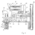
- Fig. 4 shows the turntable 10 with one of the tools partially in Cut in step position 2, i.e. at station 2 with loaded horizontally lying mandrel 12 and die 11 open at the top below an extruder 46 as a filling device.
- the extruder 46 is permanently assigned to station 2. It has a tubular part 47 on, in which a closing body 48 is located.
- the closing body 48 is designed as a valve cone and by not shown Means for opening and closing slidable in the axial direction arranged.
- the tubular part 47 is surrounded by an annular nozzle 49, which is intended to generate a gas stream.
- For filling extruder 46 extrudes a portion of material from die 11 (not shown) plasticized plastic.
- the closing body 48 flowing from the tubular part 47 Plastic flow through the closing body 48 into a ring, i.e. an annular portion of material, round to lenticular Cross-section, shaped.
- a gas stream can be applied to the portion, which the Separation of the material portion from the extruder when in the closed position driven closing body 48 supports.
- Fig. 5 shows the turntable 10 with one of the tools partially in Cut in step position 3, i.e. at station 3.
- the loaded thorn 12 is pivoted through 90 ° to the horizontal and in this position aligned for entry into the filled die.
- the entry movement of the dome 12 in the die 11 is triggered by a Toggle lever 19 (see also station 3 in FIG. 1) on a roller 50 a shaft 51 axially guided in the swivel part 35 presses and the latter in the pivot part 35 against the force of the spring 52 in the direction moves to the die 11.
- a mandrel carrier 53 arranged the mandrel 12, so that when displaced of the shaft 51, the loaded mandrel 12 into the die 11, retracting the pressing process.
- 5 are the same Parts as in Fig. 2, 3 and 4 provided with the same reference numerals.
- Fig. 6 shows a partition 15 in plan view.
- the partition 15 comprises a substantially rectangular first section 54, the same in its width B1 for a two-chamber tube Chamber dimensions essentially the diameter of a Tube plus that of the protrusions (flanges 45), and in its length L1 essentially corresponds to the length of the tube 16.
- On this section 54 closes a second section 55 at one end to that in its shape essentially the inner form corresponds to a tube head.
- Approach 43c thus corresponds with the dimensioning of the approach 43a and the slope 43d with the the slope 43b, shoulder 43a and 43b are shaped surfaces of the front free end 43 of the dome 12 (Fig. 3).
- the length L2 of the Approach 43c corresponds essentially to the length of a pouring opening, while the width B2 corresponds to their diameter.
- Inserted into the slot 17 of a mandrel 12 is the the section 55 opposite side of the partition 15 on End of the slot, while the flanges 45 of the partition 15 in essentially by molding on the surface of the dome 12 issue.
- flanges 45 are preferably in one direction of rotation bent along the longitudinal edges of section 54 so that when the partition 15 is inserted into the slot 17 of the dome 12 lie against the outer surface of the dome 12, so that the tube 16 passes over the flanges 45 on the Mandrel 12 can be applied.
- the flanges 45 are between outer surface of the dome 12 and inner surface of the Tube tube 16.
- the welding is provided at a cooling station for the head 22 with melted to make the second section 55 (station 5).
- the welding takes place through inductively generated heat development and melting of the pipe and flange material in strip form with simultaneous or subsequent pressing of the strips.
- the purpose of welding devices is the heating devices combined with pressing devices or the latter are heating devices downstream, with cooling devices following can be provided, for example by blowing the seams with air.
- Develop the flanges 45 for example A certain restoring force, i.e.
- Plastic monofilms come as materials for the manufacture of the tube tubes (Single-layer foils consisting of a plastic), Plastic laminate films (films of at least two Plastic layers) or metal laminate foils (metal foil on both sides laminated with one or more plastic films).
- the outer layers are in plastic and metal laminate films mostly made of polyethylene, which weld well against each other to let. Polyethylene is also suitable for molding the head 22 to one end of the tube 16, since polyethylene is equally well suited for injection and press molding. When choosing the material for the tube tube is due to its diffusion resistance at higher quality Packaged goods. To meet this requirement can the head outside and / or inside with a barrier layer to be occupied.
- the partition 15 preferably consists of a Plastic that matches the plastic of the inner surface of the Tube tube 16 is easy to weld.
- the partition made of a polyethylene film consists.
- Partition also made of a diffusion resistant material e.g. be made of a metal laminate.
- the inventive method was in connection with Device described above exemplified.
- the implementation of the method according to the invention is not limited to this device.
- To carry out the The method according to the invention is basically any device suitable as long as the process steps claimed with it are feasible.
- Device and method according to the invention by means of Process step injection molding operated, so is level 2 (Load the die with a portion of plasticized plastic shut down.
- liquid plastic is used in station 3 a closed form (die and patrix each form one half injected forming. Loading of the cathedral, full welding, the first and second type of partial welding takes place as in the context described with the press molding of the head.
- Station 2 is a prefabricated Head into the die - in this case not as a shaping element but introduced as a holder or receptacle.
- Station 3 drives the mandrel 12 into the die.
- One in the die possibly also heating device inserted into the patrix, softens or liquefies the plastic of an edge section of the Tube tube and / or peripheral edge section so far that the latter flow into each other to connect the head and tube.
- the side of the partition wall to connect to the inside of the head by melting.
- first type of partial connection With a full connection are transverse sides of the partitions mechanically with the heads that Long sides by welding (heat, pressure station 5) with the inner surfaces of the tube tubes connected.
- With a second Partial connection type can be from the introduction of the bulkhead side Distance and only the welding of the long sides (Station 5).
Landscapes
- Engineering & Computer Science (AREA)
- Mechanical Engineering (AREA)
- Robotics (AREA)
- Making Paper Articles (AREA)
- Tubes (AREA)
- Lining Or Joining Of Plastics Or The Like (AREA)
- Extrusion Moulding Of Plastics Or The Like (AREA)
- Packaging Of Annular Or Rod-Shaped Articles, Wearing Apparel, Cassettes, Or The Like (AREA)
- Packages (AREA)
- Injection Moulding Of Plastics Or The Like (AREA)
- Shaping Of Tube Ends By Bending Or Straightening (AREA)
Description
- Fig. 1:
- eine Pressformmaschine in der Draufsicht mit auf einem Drehtisch angeordneten Werkzeugen jeweils acht Schrittstellungen durchlaufend.
- Fig. 2:
- den Drehtisch mit einem der Werkzeuge teilweise im Schnitt in Schrittstellung 1 vor Beschickung des Dornes des Werkzeuges mit einem Tubenrohr und einer Trennwand.
- Fig. 3:
- den Drehtisch mit einem der Werkzeuge teilweise im Schnitt in Schrittstellung 1 nach Beschickung des Domes des Werkzeuges mit einem Tubenrohr und einer Trennwand.
- Fig. 4:
- den Drehtisch mit einem der Werkzeuge teilweise im Schnitt in Schrittstellung 2 mit beschicktem Dorn und nach oben offener Matrize unterhalb einer Befüllvorrichtung (Extruder).
- Fig. 5:
- den Drehtisch mit einem der Werkzeuge teilweise im Schnitt in Schrittstellung 3 mit um 90° zur Horizontalen geschwenktem Dorn vor Einfahren in die nach oben offene mit einer Materialportion (nicht dargestellt) befüllten Matrize.
- Fig. 6:
- eine Trennwand in der Draufsicht.
Claims (5)
- Verfahren zur Herstellung einer Mehrkammer-Verpackungstube aus Kunststoff, die Tube bestehend aus einem Tubenrohr, einem Schulter und Ausguss mit inneren und äusseren Oberflächen umfassenden Tubenkopf und mindestens einer im Tubenrohr aufgenommenen Trennwand, umfassend ein erstes Teilstück, deren eine Querseite mit der inneren Oberfläche der Schulter verbunden ist, bei dem der Tubenkopf vermittels eines Werkzeuges bestehend aus einer die äussere Oberfläche des Tubenkopfes bildenden Matrize und einem die innere Oberfläche des Tubenkopfes bildenden, das Tubenrohr und die Trennwand tragenden Dorn als Werkzeughälften aus aufgeschmolzenem Kunststoff durch Spritzgiessen angeformt wird, dadurch gekennzeichnet, dass die Trennwand (15) mit einem zweiten Teilstück (55), das in seiner Formgebung im wesentlichen der inneren Formgebung des Tubenkopfes (22) entspricht, während des Formgebungs-vorganges des Tubenkopfes (22) an dessen innere Oberflächen angeformt wird.
- Verfahren nach Anspruch 1, dadurch gekennzeichnet, dass die Längsseiten der Trennwand mit der inneren Oberfläche des Tubenrohres verbunden werden.
- Verfahren nach Anspruch 1, dadurch gekennzeichnet, dass der Tubenkopf als vorgefertigter Tubenkopf am Tubenrohr angebracht wird.
- Verfahren nach Anspruch 3, dadurch gekennzeichnet, dass eine Querseite der Trennwand mechanisch mit dem vorgefertigten Tubenkopf in eine Nut eingreifend verbunden wird.
- Verfahren nach einem der Ansprüche 1 - 4, dadurch gekennzeichnet, dass der Dorn mit einem Tubenrohr und anschliessend mit einer Trennwand beschickt wird.
Applications Claiming Priority (2)
| Application Number | Priority Date | Filing Date | Title |
|---|---|---|---|
| CH102898 | 1998-05-07 | ||
| CH01028/98A CH693027A5 (de) | 1998-05-07 | 1998-05-07 | Verfahren zur Herstellung einer Mehrkammer-Verpackungstube. |
Publications (3)
| Publication Number | Publication Date |
|---|---|
| EP0955152A2 EP0955152A2 (de) | 1999-11-10 |
| EP0955152A3 EP0955152A3 (de) | 2000-05-31 |
| EP0955152B1 true EP0955152B1 (de) | 2004-06-16 |
Family
ID=4200771
Family Applications (1)
| Application Number | Title | Priority Date | Filing Date |
|---|---|---|---|
| EP99810378A Expired - Lifetime EP0955152B1 (de) | 1998-05-07 | 1999-05-04 | Verfahren zur Herstellung einer Mehrkammer-Verpackungstube |
Country Status (7)
| Country | Link |
|---|---|
| US (1) | US6358454B1 (de) |
| EP (1) | EP0955152B1 (de) |
| JP (1) | JP2000025122A (de) |
| AT (1) | ATE269207T1 (de) |
| CA (1) | CA2270640C (de) |
| CH (1) | CH693027A5 (de) |
| DE (2) | DE59909721D1 (de) |
Families Citing this family (6)
| Publication number | Priority date | Publication date | Assignee | Title |
|---|---|---|---|---|
| US7213506B2 (en) * | 2003-01-24 | 2007-05-08 | Kraft Foods R & D, Inc. | Cartridge for the preparation of beverages |
| US7044333B2 (en) * | 2004-01-22 | 2006-05-16 | Church & Dwight Co., Inc. | Toothpaste tube |
| JP4415048B2 (ja) * | 2005-10-12 | 2010-02-17 | 関西チューブ株式会社 | 閉鎖型チューブの頭部形成方法、閉鎖型チューブの製造方法及び閉鎖型チューブ容器 |
| EP2821197A1 (de) * | 2013-07-03 | 2015-01-07 | Aisapack Holding SA | Indexierende Schweißvorrichtung für Rohr |
| CN112590192A (zh) * | 2020-12-01 | 2021-04-02 | 程英奇 | 一种木质拖把杆生产塑封组装装置 |
| CN115503179B (zh) * | 2022-10-08 | 2026-04-17 | 上海具新自动化设备有限公司 | 一种全自动软管高速注肩机 |
Family Cites Families (22)
| Publication number | Priority date | Publication date | Assignee | Title |
|---|---|---|---|---|
| FR961154A (de) * | 1950-05-06 | |||
| CA571175A (en) * | 1959-02-24 | Quinche Albert | Method for forming apertures in molded plastic articles | |
| CH305197A (fr) * | 1953-01-08 | 1955-02-15 | Andre Strahm | Machine pour le moulage d'un objet en matière thermoplastique. |
| US3081926A (en) * | 1961-02-01 | 1963-03-19 | Harry A Newton | Containers and closures therefor |
| US3290422A (en) * | 1962-12-28 | 1966-12-06 | American Can Co | Method of producing a dispensing container |
| FR1366792A (fr) | 1963-04-22 | 1964-07-17 | Emballages pour produits liquides, pâteux ou solides | |
| US3227319A (en) * | 1964-02-21 | 1966-01-04 | Rosier Jean-Jacques | Flexible tube |
| US3788520A (en) * | 1971-07-21 | 1974-01-29 | J Dukess | Multiple compartment tube with resilient divider |
| US3877520A (en) | 1973-08-17 | 1975-04-15 | Paul S Putnam | Subsea completion and rework system for deep water oil wells |
| US3948704A (en) | 1973-11-13 | 1976-04-06 | The Procter & Gamble Company | Method of and apparatus for making longitudinally partitioned tubular bodies and container assemblies |
| CH638716A5 (de) * | 1979-07-12 | 1983-10-14 | Karl Maegerle | Verfahren zur herstellung eines formkoerpers aus kunststoff. |
| US5219373A (en) * | 1989-07-26 | 1993-06-15 | Yoshida Industry Co., Ltd. | Method of fabricating tube container |
| US5076470A (en) * | 1989-07-26 | 1991-12-31 | Yoshida Industry Co., Ltd. | Tube container |
| DE19522169C2 (de) * | 1995-06-19 | 1997-05-28 | Automation Industrielle Sa | Verfahren zur Herstellung eines insbesondere mehrschichtigen Rohrkörpers mit mindestens einer Trennwand für eine Tube |
| US5628429A (en) | 1995-11-22 | 1997-05-13 | Enamelon, Inc. | Plural chambered squeezable dispensing tube |
| US5788794A (en) * | 1996-05-23 | 1998-08-04 | Pepsico, Inc. | Method for producing a partitioned bottle |
| DE19640833C1 (de) * | 1996-10-02 | 1997-12-18 | Automation Industrielle Sa | Vorrichtung zur Herstellung von Zwei- oder Mehrkammertuben |
| US5954224A (en) * | 1996-11-01 | 1999-09-21 | Colgate-Palmolive Company | Injection stretch blow molded tubular containers |
| US5782384A (en) * | 1996-11-05 | 1998-07-21 | Colgate-Palmolive | Aligned web in a container |
| US5849241A (en) * | 1996-12-20 | 1998-12-15 | Colgate-Palmolive Company | Multichamber container with expanded interior walls |
| US5858153A (en) * | 1997-01-17 | 1999-01-12 | Colgate-Palmolive Company | Method for making tubular containers |
| DE19712736C1 (de) * | 1997-03-26 | 1998-11-12 | Maegerle Karl Lizenz | Verfahren zur Herstellung einer Mehrkammer-Verpackungstube |
-
1998
- 1998-05-07 CH CH01028/98A patent/CH693027A5/de not_active IP Right Cessation
-
1999
- 1999-05-03 CA CA002270640A patent/CA2270640C/en not_active Expired - Fee Related
- 1999-05-04 AT AT99810378T patent/ATE269207T1/de not_active IP Right Cessation
- 1999-05-04 EP EP99810378A patent/EP0955152B1/de not_active Expired - Lifetime
- 1999-05-04 DE DE59909721T patent/DE59909721D1/de not_active Expired - Lifetime
- 1999-05-06 US US09/306,546 patent/US6358454B1/en not_active Expired - Lifetime
- 1999-05-07 DE DE19921057A patent/DE19921057A1/de not_active Withdrawn
- 1999-05-07 JP JP11127660A patent/JP2000025122A/ja active Pending
Also Published As
| Publication number | Publication date |
|---|---|
| EP0955152A3 (de) | 2000-05-31 |
| EP0955152A2 (de) | 1999-11-10 |
| CH693027A5 (de) | 2003-01-31 |
| HK1023537A1 (en) | 2000-09-15 |
| JP2000025122A (ja) | 2000-01-25 |
| ATE269207T1 (de) | 2004-07-15 |
| CA2270640C (en) | 2007-07-31 |
| DE59909721D1 (de) | 2004-07-22 |
| DE19921057A1 (de) | 1999-12-16 |
| CA2270640A1 (en) | 1999-11-07 |
| US6358454B1 (en) | 2002-03-19 |
Similar Documents
| Publication | Publication Date | Title |
|---|---|---|
| DE3587947T2 (de) | Mehrschichtiger Vorformling mit innerer Sperrschicht. | |
| DE3023415C2 (de) | ||
| EP0473769B1 (de) | Vorrichtung zur herstellung von tuben | |
| DE69517471T2 (de) | Spritzgiessverfahren mit gegenüberliegenden Anschnitten | |
| DE3587820T2 (de) | Mehrschichtiger Vorformling mit einer Schicht hoher thermischer Festigkeit. | |
| EP1183144B1 (de) | Verfahren zum herstellen von extrusionsblasgeformten behältern mit mindestens zwei kammern | |
| DE4102319C2 (de) | Verfahren und Vorrichtung zum Formen hohler Körper | |
| DE69103856T2 (de) | Vorrichtung zur Herstellung von Zellen in fortlaufenden Bäudern, vorzugsweise zum Verpacken von Suppositorien od.dgl. | |
| EP0791448A2 (de) | Verfahren und Vorrichtung zum Spritzgiessen von Kunststoffteilen | |
| EP1237794B1 (de) | Vorrichtung zur Herstellung von Zweikammerbehältern | |
| EP0867374B1 (de) | Verfahren zur Herstellung einer Mehrkammer-Verpackungstube | |
| DE3439285C2 (de) | Verfahren zum Herstellen eines Hohlkörpers aus thermoplastischem Kunststoff und Vorrichtung zum Durchführen des Verfahrens | |
| DE2649721B2 (de) | Behälter und Verfahren und Vorrichtung zu dessen Herstellung | |
| DE2842515C2 (de) | Verfahren zum Herstellen von Kopfstücken mit einer Membrane für Verpackungsbehälter aus Laminat mit einer metallischen Sperrschicht und Vorrichtung zur Durchführung des Verfahrens | |
| EP0955152B1 (de) | Verfahren zur Herstellung einer Mehrkammer-Verpackungstube | |
| DE69627824T2 (de) | Verfahren und vorrichtung zum herstellen von rohrfoermigen behaeltern mit verschlussvorrichtung | |
| DE4236439A1 (de) | Verfahren und Vorrichtung zum Herstellen von Hohlkörpern aus thermoplastischem Kunststoff | |
| DE2649526A1 (de) | Verfahren zum herstellen eines hauptsaechlich aus thermoplastischem material bestehendem mehrschichtigen behaelters und form zur ausfuehrung des verfahrens | |
| DE60201516T2 (de) | Verfahren und vorrichtung zur herstellung von behälterstreifen | |
| EP1208955B1 (de) | Spritzgussverfahren mit variablem Formhohlraum zur Herstellung von Korken | |
| EP0228616A2 (de) | Verfahren und Vorrichtung zum Herstellen von Hohlkörpern aus thermoplastischen Kunststoffen | |
| EP0419829A2 (de) | Verfahren und Vorrichtung zum Herstellen von Behältern für Lebensmittel u.dgl. | |
| EP2801465B1 (de) | Verfahren zur Herstellung eines Behälters mit einem flexiblen Innenbeutel | |
| DE102007015216B4 (de) | Vorrichtung und Verfahren zur Herstellung eines Hohlkörpers aus mindestens zwei Schichten Kunststoff | |
| DE19935139C2 (de) | Verfahren und Vorrichtung zum Herstellen eines Kunststoffkörpers |
Legal Events
| Date | Code | Title | Description |
|---|---|---|---|
| PUAI | Public reference made under article 153(3) epc to a published international application that has entered the european phase |
Free format text: ORIGINAL CODE: 0009012 |
|
| AK | Designated contracting states |
Kind code of ref document: A2 Designated state(s): AT BE CH CY DE DK ES FI FR GB GR IE IT LI LU MC NL PT SE |
|
| AX | Request for extension of the european patent |
Free format text: AL;LT;LV;MK;RO;SI |
|
| PUAL | Search report despatched |
Free format text: ORIGINAL CODE: 0009013 |
|
| AK | Designated contracting states |
Kind code of ref document: A3 Designated state(s): AT BE CH CY DE DK ES FI FR GB GR IE IT LI LU MC NL PT SE |
|
| AX | Request for extension of the european patent |
Free format text: AL;LT;LV;MK;RO;SI |
|
| 17P | Request for examination filed |
Effective date: 20001117 |
|
| AKX | Designation fees paid |
Free format text: AT BE CH CY DE DK ES FI FR GB GR IE IT LI LU MC NL PT SE |
|
| 17Q | First examination report despatched |
Effective date: 20010705 |
|
| GRAP | Despatch of communication of intention to grant a patent |
Free format text: ORIGINAL CODE: EPIDOSNIGR1 |
|
| GRAS | Grant fee paid |
Free format text: ORIGINAL CODE: EPIDOSNIGR3 |
|
| GRAA | (expected) grant |
Free format text: ORIGINAL CODE: 0009210 |
|
| AK | Designated contracting states |
Kind code of ref document: B1 Designated state(s): AT BE CH CY DE DK ES FI FR GB GR IE IT LI LU MC NL PT SE |
|
| PG25 | Lapsed in a contracting state [announced via postgrant information from national office to epo] |
Ref country code: NL Free format text: LAPSE BECAUSE OF FAILURE TO SUBMIT A TRANSLATION OF THE DESCRIPTION OR TO PAY THE FEE WITHIN THE PRESCRIBED TIME-LIMIT Effective date: 20040616 Ref country code: IT Free format text: LAPSE BECAUSE OF FAILURE TO SUBMIT A TRANSLATION OF THE DESCRIPTION OR TO PAY THE FEE WITHIN THE PRESCRIBED TIME-LIMIT;WARNING: LAPSES OF ITALIAN PATENTS WITH EFFECTIVE DATE BEFORE 2007 MAY HAVE OCCURRED AT ANY TIME BEFORE 2007. THE CORRECT EFFECTIVE DATE MAY BE DIFFERENT FROM THE ONE RECORDED. Effective date: 20040616 Ref country code: IE Free format text: LAPSE BECAUSE OF FAILURE TO SUBMIT A TRANSLATION OF THE DESCRIPTION OR TO PAY THE FEE WITHIN THE PRESCRIBED TIME-LIMIT Effective date: 20040616 Ref country code: GB Free format text: LAPSE BECAUSE OF FAILURE TO SUBMIT A TRANSLATION OF THE DESCRIPTION OR TO PAY THE FEE WITHIN THE PRESCRIBED TIME-LIMIT Effective date: 20040616 Ref country code: FI Free format text: LAPSE BECAUSE OF FAILURE TO SUBMIT A TRANSLATION OF THE DESCRIPTION OR TO PAY THE FEE WITHIN THE PRESCRIBED TIME-LIMIT Effective date: 20040616 Ref country code: ES Free format text: LAPSE BECAUSE OF FAILURE TO SUBMIT A TRANSLATION OF THE DESCRIPTION OR TO PAY THE FEE WITHIN THE PRESCRIBED TIME-LIMIT Effective date: 20040616 |
|
| REG | Reference to a national code |
Ref country code: GB Ref legal event code: FG4D Free format text: NOT ENGLISH |
|
| REG | Reference to a national code |
Ref country code: CH Ref legal event code: EP |
|
| REF | Corresponds to: |
Ref document number: 59909721 Country of ref document: DE Date of ref document: 20040722 Kind code of ref document: P |
|
| REG | Reference to a national code |
Ref country code: IE Ref legal event code: FG4D Free format text: GERMAN |
|
| PG25 | Lapsed in a contracting state [announced via postgrant information from national office to epo] |
Ref country code: SE Free format text: LAPSE BECAUSE OF FAILURE TO SUBMIT A TRANSLATION OF THE DESCRIPTION OR TO PAY THE FEE WITHIN THE PRESCRIBED TIME-LIMIT Effective date: 20040916 Ref country code: GR Free format text: LAPSE BECAUSE OF FAILURE TO SUBMIT A TRANSLATION OF THE DESCRIPTION OR TO PAY THE FEE WITHIN THE PRESCRIBED TIME-LIMIT Effective date: 20040916 Ref country code: DK Free format text: LAPSE BECAUSE OF FAILURE TO SUBMIT A TRANSLATION OF THE DESCRIPTION OR TO PAY THE FEE WITHIN THE PRESCRIBED TIME-LIMIT Effective date: 20040916 |
|
| REG | Reference to a national code |
Ref country code: CH Ref legal event code: NV Representative=s name: HIEBSCH & PEEGE AG PATENTANWAELTE |
|
| NLV1 | Nl: lapsed or annulled due to failure to fulfill the requirements of art. 29p and 29m of the patents act | ||
| REG | Reference to a national code |
Ref country code: HK Ref legal event code: GR Ref document number: 1023537 Country of ref document: HK |
|
| GBV | Gb: ep patent (uk) treated as always having been void in accordance with gb section 77(7)/1977 [no translation filed] |
Effective date: 20040616 |
|
| REG | Reference to a national code |
Ref country code: IE Ref legal event code: FD4D |
|
| ET | Fr: translation filed | ||
| PLBE | No opposition filed within time limit |
Free format text: ORIGINAL CODE: 0009261 |
|
| STAA | Information on the status of an ep patent application or granted ep patent |
Free format text: STATUS: NO OPPOSITION FILED WITHIN TIME LIMIT |
|
| PG25 | Lapsed in a contracting state [announced via postgrant information from national office to epo] |
Ref country code: LU Free format text: LAPSE BECAUSE OF NON-PAYMENT OF DUE FEES Effective date: 20050504 Ref country code: CY Free format text: LAPSE BECAUSE OF FAILURE TO SUBMIT A TRANSLATION OF THE DESCRIPTION OR TO PAY THE FEE WITHIN THE PRESCRIBED TIME-LIMIT Effective date: 20050504 Ref country code: AT Free format text: LAPSE BECAUSE OF NON-PAYMENT OF DUE FEES Effective date: 20050504 |
|
| PG25 | Lapsed in a contracting state [announced via postgrant information from national office to epo] |
Ref country code: MC Free format text: LAPSE BECAUSE OF NON-PAYMENT OF DUE FEES Effective date: 20050531 Ref country code: BE Free format text: LAPSE BECAUSE OF NON-PAYMENT OF DUE FEES Effective date: 20050531 |
|
| 26N | No opposition filed |
Effective date: 20050317 |
|
| BERE | Be: lapsed |
Owner name: *KMK LIZENCE LTD Effective date: 20050531 |
|
| BERE | Be: lapsed |
Owner name: *KMK LIZENCE LTD Effective date: 20050531 |
|
| PG25 | Lapsed in a contracting state [announced via postgrant information from national office to epo] |
Ref country code: PT Free format text: LAPSE BECAUSE OF NON-PAYMENT OF DUE FEES Effective date: 20041116 |
|
| REG | Reference to a national code |
Ref country code: CH Ref legal event code: PFA Owner name: KMK LIZENCE LTD. Free format text: KMK LIZENCE LTD.#SIXTH FLOOR, CERNE HOUSE#CHAUSSEE, PORT LOUIS (MU) -TRANSFER TO- KMK LIZENCE LTD.#SIXTH FLOOR, CERNE HOUSE#CHAUSSEE, PORT LOUIS (MU) |
|
| PGFP | Annual fee paid to national office [announced via postgrant information from national office to epo] |
Ref country code: DE Payment date: 20120523 Year of fee payment: 14 |
|
| PG25 | Lapsed in a contracting state [announced via postgrant information from national office to epo] |
Ref country code: DE Free format text: LAPSE BECAUSE OF NON-PAYMENT OF DUE FEES Effective date: 20131203 |
|
| REG | Reference to a national code |
Ref country code: DE Ref legal event code: R119 Ref document number: 59909721 Country of ref document: DE Effective date: 20131203 |
|
| PGFP | Annual fee paid to national office [announced via postgrant information from national office to epo] |
Ref country code: CH Payment date: 20140521 Year of fee payment: 16 Ref country code: FR Payment date: 20140527 Year of fee payment: 16 |
|
| REG | Reference to a national code |
Ref country code: CH Ref legal event code: PL |
|
| PG25 | Lapsed in a contracting state [announced via postgrant information from national office to epo] |
Ref country code: CH Free format text: LAPSE BECAUSE OF NON-PAYMENT OF DUE FEES Effective date: 20150531 Ref country code: LI Free format text: LAPSE BECAUSE OF NON-PAYMENT OF DUE FEES Effective date: 20150531 |
|
| REG | Reference to a national code |
Ref country code: FR Ref legal event code: ST Effective date: 20160129 |
|
| PG25 | Lapsed in a contracting state [announced via postgrant information from national office to epo] |
Ref country code: FR Free format text: LAPSE BECAUSE OF NON-PAYMENT OF DUE FEES Effective date: 20150601 |