EP0955152B1 - Process for making a multi-compartment packaging tube - Google Patents
Process for making a multi-compartment packaging tube Download PDFInfo
- Publication number
- EP0955152B1 EP0955152B1 EP99810378A EP99810378A EP0955152B1 EP 0955152 B1 EP0955152 B1 EP 0955152B1 EP 99810378 A EP99810378 A EP 99810378A EP 99810378 A EP99810378 A EP 99810378A EP 0955152 B1 EP0955152 B1 EP 0955152B1
- Authority
- EP
- European Patent Office
- Prior art keywords
- tube
- head
- partition
- mandrel
- die
- Prior art date
- Legal status (The legal status is an assumption and is not a legal conclusion. Google has not performed a legal analysis and makes no representation as to the accuracy of the status listed.)
- Expired - Lifetime
Links
Images


Classifications
-
- B—PERFORMING OPERATIONS; TRANSPORTING
- B29—WORKING OF PLASTICS; WORKING OF SUBSTANCES IN A PLASTIC STATE IN GENERAL
- B29C—SHAPING OR JOINING OF PLASTICS; SHAPING OF MATERIAL IN A PLASTIC STATE, NOT OTHERWISE PROVIDED FOR; AFTER-TREATMENT OF THE SHAPED PRODUCTS, e.g. REPAIRING
- B29C43/00—Compression moulding, i.e. applying external pressure to flow the moulding material; Apparatus therefor
- B29C43/02—Compression moulding, i.e. applying external pressure to flow the moulding material; Apparatus therefor of articles of definite length, i.e. discrete articles
- B29C43/18—Compression moulding, i.e. applying external pressure to flow the moulding material; Apparatus therefor of articles of definite length, i.e. discrete articles incorporating preformed parts or layers, e.g. compression moulding around inserts or for coating articles
-
- B—PERFORMING OPERATIONS; TRANSPORTING
- B29—WORKING OF PLASTICS; WORKING OF SUBSTANCES IN A PLASTIC STATE IN GENERAL
- B29C—SHAPING OR JOINING OF PLASTICS; SHAPING OF MATERIAL IN A PLASTIC STATE, NOT OTHERWISE PROVIDED FOR; AFTER-TREATMENT OF THE SHAPED PRODUCTS, e.g. REPAIRING
- B29C31/00—Handling, e.g. feeding of the material to be shaped, storage of plastics material before moulding; Automation, i.e. automated handling lines in plastics processing plants, e.g. using manipulators or robots
- B29C31/002—Handling tubes, e.g. transferring between shaping stations, loading on mandrels
-
- B—PERFORMING OPERATIONS; TRANSPORTING
- B29—WORKING OF PLASTICS; WORKING OF SUBSTANCES IN A PLASTIC STATE IN GENERAL
- B29C—SHAPING OR JOINING OF PLASTICS; SHAPING OF MATERIAL IN A PLASTIC STATE, NOT OTHERWISE PROVIDED FOR; AFTER-TREATMENT OF THE SHAPED PRODUCTS, e.g. REPAIRING
- B29C43/00—Compression moulding, i.e. applying external pressure to flow the moulding material; Apparatus therefor
- B29C43/32—Component parts, details or accessories; Auxiliary operations
- B29C43/36—Moulds for making articles of definite length, i.e. discrete articles
- B29C43/42—Moulds for making articles of definite length, i.e. discrete articles for undercut articles
-
- B—PERFORMING OPERATIONS; TRANSPORTING
- B29—WORKING OF PLASTICS; WORKING OF SUBSTANCES IN A PLASTIC STATE IN GENERAL
- B29D—PRODUCING PARTICULAR ARTICLES FROM PLASTICS OR FROM SUBSTANCES IN A PLASTIC STATE
- B29D23/00—Producing tubular articles
- B29D23/20—Flexible squeeze tubes, e.g. for cosmetics
-
- B—PERFORMING OPERATIONS; TRANSPORTING
- B29—WORKING OF PLASTICS; WORKING OF SUBSTANCES IN A PLASTIC STATE IN GENERAL
- B29C—SHAPING OR JOINING OF PLASTICS; SHAPING OF MATERIAL IN A PLASTIC STATE, NOT OTHERWISE PROVIDED FOR; AFTER-TREATMENT OF THE SHAPED PRODUCTS, e.g. REPAIRING
- B29C43/00—Compression moulding, i.e. applying external pressure to flow the moulding material; Apparatus therefor
- B29C43/32—Component parts, details or accessories; Auxiliary operations
- B29C43/36—Moulds for making articles of definite length, i.e. discrete articles
- B29C43/361—Moulds for making articles of definite length, i.e. discrete articles with pressing members independently movable of the parts for opening or closing the mould, e.g. movable pistons
- B29C2043/3615—Forming elements, e.g. mandrels or rams or stampers or pistons or plungers or punching devices
-
- B—PERFORMING OPERATIONS; TRANSPORTING
- B29—WORKING OF PLASTICS; WORKING OF SUBSTANCES IN A PLASTIC STATE IN GENERAL
- B29L—INDEXING SCHEME ASSOCIATED WITH SUBCLASS B29C, RELATING TO PARTICULAR ARTICLES
- B29L2001/00—Articles provided with screw threads
-
- B—PERFORMING OPERATIONS; TRANSPORTING
- B29—WORKING OF PLASTICS; WORKING OF SUBSTANCES IN A PLASTIC STATE IN GENERAL
- B29L—INDEXING SCHEME ASSOCIATED WITH SUBCLASS B29C, RELATING TO PARTICULAR ARTICLES
- B29L2023/00—Tubular articles
- B29L2023/20—Flexible squeeze tubes, e.g. for cosmetics
-
- B—PERFORMING OPERATIONS; TRANSPORTING
- B29—WORKING OF PLASTICS; WORKING OF SUBSTANCES IN A PLASTIC STATE IN GENERAL
- B29L—INDEXING SCHEME ASSOCIATED WITH SUBCLASS B29C, RELATING TO PARTICULAR ARTICLES
- B29L2031/00—Other particular articles
- B29L2031/712—Containers; Packaging elements or accessories, Packages
-
- Y—GENERAL TAGGING OF NEW TECHNOLOGICAL DEVELOPMENTS; GENERAL TAGGING OF CROSS-SECTIONAL TECHNOLOGIES SPANNING OVER SEVERAL SECTIONS OF THE IPC; TECHNICAL SUBJECTS COVERED BY FORMER USPC CROSS-REFERENCE ART COLLECTIONS [XRACs] AND DIGESTS
- Y10—TECHNICAL SUBJECTS COVERED BY FORMER USPC
- Y10S—TECHNICAL SUBJECTS COVERED BY FORMER USPC CROSS-REFERENCE ART COLLECTIONS [XRACs] AND DIGESTS
- Y10S264/00—Plastic and nonmetallic article shaping or treating: processes
- Y10S264/41—Processes of molding collapsible tubes
Definitions
- the invention relates to a method for producing a multi-chamber packaging tube according to the preamble of the claim 1.
- Multi-chamber packaging tubes are tubes with at least one Partition wall included in them for receiving up to theirs Removal of packaging goods to be kept separately, e.g. components a commodity that is only used for association should arrive. Commodities of this type appear on the Field of technology, hygiene, cosmetics and pharmacy increased in the foreground.
- Methods for producing multi-chamber tubes are known. Basically, the known methods are of two types and in assembly processes and molding processes (forming process) distinguished. The difference in The procedure is that the assembly process involves using tubes Partitions are assembled from individual parts while in the forming process tube tube with partition or head with Partition (i.e. always at least two tube components) in formed and then, e.g. Tube and Partition with head or head and partition with tube, be united.
- An assembly method in which a prefabricated Tube tube with an equally prefabricated tube head is connected. Then a wrinkled, in its longitudinal and transverse direction resilient partition in the Tube tube inserted.
- the partition i.e. a their transverse sides connected to the tube head by gluing, while the other transverse side with the closing seam of the tube is united. Due to the transverse and / or The partition wall is tensioned by longitudinal spring forces with their long sides against the inside of the tube and if no gluing is provided on the inside of the tube head between the closing seam and the tube head.
- a well-known molding process is characterized by that initially formed a head with a partition and then the head designed in this way with a tube is united.
- the disadvantage of this method is the overall complex automation (GB PS 1,030,275 to Rosier).
- a molding method using is also known a die and a mandrel, in which the mandrel either with a pipe pre-assembled with a partition or is loaded individually with pipe and partition.
- This The process leaves the formation of the partition in the head to the Head forming process by injection molding and it melts the partition in the pipe to the partition in the head.
- This Connections have proven to be insufficiently resilient proven (DE 196 40 833 C1, AISA Automation Industrielle SA).
- the invention has the object Basically, a process for producing multi-chamber tubes too create that the disadvantages of the assembly and molding process avoids and this task is accomplished by means of a procedure solved the features of claim 1.
- the invention is based on one of the tube manufacturing methods mentioned common process step - loading one Domes with a tube - to complete or add the Loading a mandrel with a prefabricated partition.
- the Loading with a partition can be done much faster will be the introduction of a Partition into a tube or the connection in the molding process a preformed tube with e.g. a partition of the tube continuing to the head, whereby the inventive method with respect to Application to multi-chamber tubes per unit of time Single-chamber tubes comes very close, so with the procedure
- a multi-chamber tube is comparably economical how single-chamber tubes are to be manufactured.
- the procedure according to the invention can be carried out as long as one Die and a mandrel the determining technical means for Are performing the procedure.
- Matrix and mandrel act as a head-forming form, in the latter liquid plastic injected under pressure (injection molding) or a certain amount of plasticized plastic under pressure is formed into a head by the mandrel (Molds). Since the mandrel in both cases the tube and according to the invention carries the partition, the tube is at Formation process of the head associated with the latter as well as that partition protruding into the head, unless it were Precautions taken, the partition not with the connecting the forming head.
- the die does not act on the head with respect to the head form-forming, but rather as the holder and holder of one of them Contour essentially corresponding prefabricated head and Device for melting the edge of the head and / or one pipe end positioned on a mandrel for both connections.
- the die can be localized to the head and / or melt the pipe with the partition so that the pipe and, if desired, partition is connected to the head become.
- the matrix is in relation to the one according to the invention Procedure in its function not on a formative Process element limited, but this also extends on bracket and heating. The same applies to the cathedral, which at the molding process as a mounting and shaping element, the attachment method as a holder for tube tube and Partition works. In the sense of the invention and before this The background is the matrix and the dome for molding and Attachment method functional functional equivalents.
- the connection of the transverse side of a partition to the head can be done in different ways.
- the short side is poured in Short side, i.e. one edge strip each on the transverse side during the Formation of the head in the plasticized plastic (PE) formed.
- PE plasticized plastic
- an adhesive or mechanical Attachment are provided, e.g. in the form of a groove that the inner surface of the head runs along and into an edge section the short side can be inserted. Should the partition remain unconnected to the head when gating and molding means to provide the edge portions of the Transverse sides opposite the injected or plasticized Cover plastics.
- Means for this could be disks that the front surface of a dome with inserted partition, Cover edge sections and cut edges. Remain long sides the partitions are not connected to the inner surface, so they lie on the inner surface, against the latter pressure exercising on.
- This can be done by designing the partition, e.g. in cross section "S" -shaped and thus in the opening direction of the "S" shaped design resilient or due to memory effect Restoring forces, for example, rounded flanges along the Long sides of the existing like tubes of plastic Partitions are created.
- the connection of the long sides with The inner surface of a tube tube can be glued or welding, the latter using Heat and pressure.
- the plastic of the partition i.e. e.g. one of the flanges running along the long side and possibly a strip opposite the flange along the plasticized or melted inner surface of the tube and flange and strip pressed together.
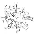
- Fig. 1 shows the rotary body designed as a rotary table 10 in the Top view.
- On the turntable 10 are in the circumferential direction in evenly spaced between dies 11 and mandrels 12, a mandrel 12 being associated with each die 11.
- the matrices 11 are open upwards and the domes 12 are made of one horizontal position at an angle of 90 ° to each Matrices 11 coaxial vertical position on the turntable 10 pivotally arranged.
- the mandrels are in the same-axis position 12 axially displaceable to close the associated die 11 and being able to open it again.
- the Rotary table 10 by one step position in the direction of arrow 13 can be driven by means not shown.
- the mandrel 12 is first with a Partition 15 and then with a prefabricated tube 16 loaded.
- the partition 15 is in a slot 17 of the dome 12 added, the flanges 45 on the Form molded mandrel so that the tube 16 over the cathedral 12 and the flanges 45, running tightly over the latter, can be pushed.
- Fitting means a distance between flange 45 and inner surface of the dome of 0.05 mm to 1.0 mm, preferably 0.4 to 0.8 mm.
- the dome 12 is in a horizontal position, so that the loading takes place in the horizontal direction.
- Station 2 is assigned a fixed material feeder 18.
- this material dispenser 14 a portion (not shown) plasticized plastic in the by the material provider 18th covered upwardly open die 11 introduced in free fall.
- Another type of loading can be the material portion the die in its longitudinal direction (vertical) drive through the material carrier, which is the material portion in the position intended for them in the die.
- the position and representation of the die 11 is illustrated in position 7.
- the mandrel 12 remains in the pressed position, so that the pressed Tube head with fused tube 16 and on the head melted-down partition 15 can cool and harden.
- die 11 and mandrel 12 are not shown Connections cooled by a coolant.
- the mandrel 12 remains in the press position for cooling.
- An inductively acting one can preferably enter this station 5
- Welding device 20 may be integrated, which is close to the flanges 45 its longitudinal edges of the partition 15 (long sides) with the connects the inner surface of the tube, i.e. welded.
- the fusion takes place by the material, i.e. plastic near the longitudinal edges and an opposite one in Longitudinal direction of the tube tube 16 extending strip-shaped Zone melted and preferably engaged under pressure i.e. be pressed together.
- the welding device 20 is not on the turntable 10, but like the loading device 14 arranged peripherally separate from the latter. To make one The welding device 20 travels in the direction of the arrow horizontally and thus brings heating and pressure devices in Working position.
- the mandrel 12 becomes axial Extends direction out of the die 11 and that is from Die 11 and mandrel 12 existing pressing tool (die 11 and mandrel 12) opened again after the thread on Tube head forming die part 28 by means not shown released the formed thread, for example by spreading mold jaws apart.
- the Position 6 in position 7 becomes the mandrel 12 with tube tube 16 molded head and partition 15 connected to the latter swung back into the horizontal position.
- a shutter 24 i.e. a cap 24 on the tube head 22 screwed on, or pushed open with plug caps.
- the process of the device comprises eight process steps related to the device, clock steps called one to eight, with process step 7 (Application of a cap 24 to the tube head 22) for the implementation of the method according to the invention is not mandatory.
- process step 7 Application of a cap 24 to the tube head 22
- eight stations, at which said eight procedural steps are implemented, are specified, it is also possible to follow the eight process steps to a different number of stations less than eight or larger e.g. to distribute ten stations. So there could be eight between the station and one another station with a loading device be provided which the mandrel 12 previously for loading with the Tube tube 16 is only equipped with the partition 15.
- stations 3 and 4, or 4 and 5, or 5 and 6 could be provided, on which the partition longitudinal weld by means of the welding device could.
- all in connection with FIG. 1 described combined process steps can be Individual adjustment of the number of stations. It can but less than eight stations may also be provided if Functions for the production of a multi-chamber tube summarized become.
- Fig. 2 shows the turntable 10 with one of the tools partially in Cut in step position 1, i.e. at station 1 before loading the horizontally extending mandrel 12 with partition 15 and below Tube tube 16.
- a fixed shaft is designated, around which the turntable 10 is rotatably supported and not shown means is driven gradually.
- the die 11 having the mold cavity 27 embedded and attached.
- the mold cavity corresponds to the outer boundary of the tube head 22 (Fig. 1).
- a further die part 28 in which a further mold cavity 29 for forming the thread on the Tube head 22 is arranged.
- the punch 31 is through Spring 30 loaded in the direction of the mold cavity 27 and Introduction of the mandrel 12 into the die 11 against the force of the Spring 30 pushed back.
- the punch 31 serves to keep it free the tube opening when pressing the tube head 22.
- Das Die part 28 is rotatable about a further axis, around the To be able to release the thread of the pressed tube head. It is rotated by means not shown, or in place opened for rotation by other means (not shown).
- the mandrel 12 is arranged pivotable about an axis 32.
- a pivoting device is used, for example, to pivot a rack 33, which with its teeth 34 in the toothing a pivoting part 35 engages.
- the rack 33 is connected with a plunger 36, which in two on the turntable 10 fixed bearing blocks 37, 38 axially slidably mounted is.
- the plunger 36 with a Driver 39 rigidly connected, which is a guide roller 40th has, which is fixed in a guide groove 41 such as the shaft 26 Cam 42 is guided.
- the guide groove 41 has in the cam 42 such a course that the driver 39 moved back and forth between the bearing blocks 37, 38 is, whereby the mandrel 11 in vertical through the means described or horizontal position is pivoted.
- the mandrel 12 shown in Fig. 3 is at its front free End 43 designed so that the free end 43 (end face of the Domes) can form the inner contour of a tube head 22.
- the approach 43a forms the flow opening of the spout of the tube head 22 during the subsequent one Bevel 43b the inner surface of the shoulder of the tube head 22 shaped.
- a slot 17 extends through to accommodate a partition 15 axial direction of the dome 12, starting from the front free end face of the projection 43a in an extension, the corresponds to the length of a partition 15. In this slot 17th the partition 15 is inserted by the loading device 14.
- Fig. 3 shows the rotary table 10 with one of the tools partially in Cut in step position 1, i.e. in station 1 in contrast to Fig. 2 but after loading the still horizontal Dome 12 with a partition 15 and a tube tube 16.
- the cut (Fig. 6) of a partition 15 is preferably so made it one end in its outer shape the front free end 43 of the dome 12 (contouring the Transverse side), and then at least in width half the circumference of the cathedral and its length the length a tube preferably starting from the front free end of the Approach 43a corresponds, the bilateral projection of the Partition is created on the mandrel. This is the partition 15 completely and with the same shape as the protrusions Surface of the mandrel 12 received in the mandrel 12.
- the protrusions of the partition are as flanges 45 referred to, the strip-shaped longitudinal seam welding allow. These flanges are on both sides of the partition 15 (according to the mandrel diameter) bent, lie on the inner surface of the tube 22 and each have a Width formed from half the difference between half Circumference of the tube and the mandrel diameter, preferably increases by 5% to 25%, preferably 8% to 12% of the width.
- Fig. 3 are the same parts as in Fig. 2 with the same reference numerals characterized.
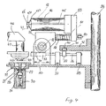
- Fig. 4 shows the turntable 10 with one of the tools partially in Cut in step position 2, i.e. at station 2 with loaded horizontally lying mandrel 12 and die 11 open at the top below an extruder 46 as a filling device.
- the extruder 46 is permanently assigned to station 2. It has a tubular part 47 on, in which a closing body 48 is located.
- the closing body 48 is designed as a valve cone and by not shown Means for opening and closing slidable in the axial direction arranged.
- the tubular part 47 is surrounded by an annular nozzle 49, which is intended to generate a gas stream.
- For filling extruder 46 extrudes a portion of material from die 11 (not shown) plasticized plastic.
- the closing body 48 flowing from the tubular part 47 Plastic flow through the closing body 48 into a ring, i.e. an annular portion of material, round to lenticular Cross-section, shaped.
- a gas stream can be applied to the portion, which the Separation of the material portion from the extruder when in the closed position driven closing body 48 supports.
- Fig. 5 shows the turntable 10 with one of the tools partially in Cut in step position 3, i.e. at station 3.
- the loaded thorn 12 is pivoted through 90 ° to the horizontal and in this position aligned for entry into the filled die.
- the entry movement of the dome 12 in the die 11 is triggered by a Toggle lever 19 (see also station 3 in FIG. 1) on a roller 50 a shaft 51 axially guided in the swivel part 35 presses and the latter in the pivot part 35 against the force of the spring 52 in the direction moves to the die 11.
- a mandrel carrier 53 arranged the mandrel 12, so that when displaced of the shaft 51, the loaded mandrel 12 into the die 11, retracting the pressing process.
- 5 are the same Parts as in Fig. 2, 3 and 4 provided with the same reference numerals.
- Fig. 6 shows a partition 15 in plan view.
- the partition 15 comprises a substantially rectangular first section 54, the same in its width B1 for a two-chamber tube Chamber dimensions essentially the diameter of a Tube plus that of the protrusions (flanges 45), and in its length L1 essentially corresponds to the length of the tube 16.
- On this section 54 closes a second section 55 at one end to that in its shape essentially the inner form corresponds to a tube head.
- Approach 43c thus corresponds with the dimensioning of the approach 43a and the slope 43d with the the slope 43b, shoulder 43a and 43b are shaped surfaces of the front free end 43 of the dome 12 (Fig. 3).
- the length L2 of the Approach 43c corresponds essentially to the length of a pouring opening, while the width B2 corresponds to their diameter.
- Inserted into the slot 17 of a mandrel 12 is the the section 55 opposite side of the partition 15 on End of the slot, while the flanges 45 of the partition 15 in essentially by molding on the surface of the dome 12 issue.
- flanges 45 are preferably in one direction of rotation bent along the longitudinal edges of section 54 so that when the partition 15 is inserted into the slot 17 of the dome 12 lie against the outer surface of the dome 12, so that the tube 16 passes over the flanges 45 on the Mandrel 12 can be applied.
- the flanges 45 are between outer surface of the dome 12 and inner surface of the Tube tube 16.
- the welding is provided at a cooling station for the head 22 with melted to make the second section 55 (station 5).
- the welding takes place through inductively generated heat development and melting of the pipe and flange material in strip form with simultaneous or subsequent pressing of the strips.
- the purpose of welding devices is the heating devices combined with pressing devices or the latter are heating devices downstream, with cooling devices following can be provided, for example by blowing the seams with air.
- Develop the flanges 45 for example A certain restoring force, i.e.
- Plastic monofilms come as materials for the manufacture of the tube tubes (Single-layer foils consisting of a plastic), Plastic laminate films (films of at least two Plastic layers) or metal laminate foils (metal foil on both sides laminated with one or more plastic films).
- the outer layers are in plastic and metal laminate films mostly made of polyethylene, which weld well against each other to let. Polyethylene is also suitable for molding the head 22 to one end of the tube 16, since polyethylene is equally well suited for injection and press molding. When choosing the material for the tube tube is due to its diffusion resistance at higher quality Packaged goods. To meet this requirement can the head outside and / or inside with a barrier layer to be occupied.
- the partition 15 preferably consists of a Plastic that matches the plastic of the inner surface of the Tube tube 16 is easy to weld.
- the partition made of a polyethylene film consists.
- Partition also made of a diffusion resistant material e.g. be made of a metal laminate.
- the inventive method was in connection with Device described above exemplified.
- the implementation of the method according to the invention is not limited to this device.
- To carry out the The method according to the invention is basically any device suitable as long as the process steps claimed with it are feasible.
- Device and method according to the invention by means of Process step injection molding operated, so is level 2 (Load the die with a portion of plasticized plastic shut down.
- liquid plastic is used in station 3 a closed form (die and patrix each form one half injected forming. Loading of the cathedral, full welding, the first and second type of partial welding takes place as in the context described with the press molding of the head.
- Station 2 is a prefabricated Head into the die - in this case not as a shaping element but introduced as a holder or receptacle.
- Station 3 drives the mandrel 12 into the die.
- One in the die possibly also heating device inserted into the patrix, softens or liquefies the plastic of an edge section of the Tube tube and / or peripheral edge section so far that the latter flow into each other to connect the head and tube.
- the side of the partition wall to connect to the inside of the head by melting.
- first type of partial connection With a full connection are transverse sides of the partitions mechanically with the heads that Long sides by welding (heat, pressure station 5) with the inner surfaces of the tube tubes connected.
- With a second Partial connection type can be from the introduction of the bulkhead side Distance and only the welding of the long sides (Station 5).
Landscapes
- Engineering & Computer Science (AREA)
- Mechanical Engineering (AREA)
- Robotics (AREA)
- Making Paper Articles (AREA)
- Tubes (AREA)
- Lining Or Joining Of Plastics Or The Like (AREA)
- Extrusion Moulding Of Plastics Or The Like (AREA)
- Packaging Of Annular Or Rod-Shaped Articles, Wearing Apparel, Cassettes, Or The Like (AREA)
- Packages (AREA)
- Injection Moulding Of Plastics Or The Like (AREA)
- Shaping Of Tube Ends By Bending Or Straightening (AREA)
Abstract
Description
Die Erfindung betrifft ein Verfahren zur Herstellung einer Mehrkammer-Verpackungstube nach dem Oberbegriff des Patentanspruches 1.The invention relates to a method for producing a multi-chamber packaging tube according to the preamble of the claim 1.
Mehrkammer-Verpackungstuben sind Tuben mit mindestens einer in ihnen aufgenommenen Trennwand zur Aufnahme bis zur ihrer Entnahme getrennt zu haltender Verpackungsgüter, z.B. Komponenten eines Gebrauchsgutes, die erst bei Gebrauch zur Vereinigung gelangen sollen. Gebrauchsgüter dieser Art treten auf dem Gebiet der Technik, Hygiene, Kosmetik und Pharmazie vermehrt in den Vordergrund.Multi-chamber packaging tubes are tubes with at least one Partition wall included in them for receiving up to theirs Removal of packaging goods to be kept separately, e.g. components a commodity that is only used for association should arrive. Commodities of this type appear on the Field of technology, hygiene, cosmetics and pharmacy increased in the foreground.
Verfahren zur Herstellung von Mehrkammertuben sind bekannt. Grundsätzlich sind die bekannten Verfahren in zwei Arten und zwar in Montageverfahren (assembler processes) und Formungsverfahren (forming process) unterschieden. Der Unterschied der Verfahren liegt darin, dass beim Montageverfahren Tuben mit Trennwänden aus Einzelteilen zusammengesetzt werden, während beim Formungsverfahren Tubenrohr mit Trennwand oder Kopf mit Trennwand (also immer mindestens zwei Tubenkomponenten) in einem Arbeitsgang gebildet und anschliessend, z.B. Tubenrohr und Trennwand mit Kopf oder Kopf und Trennwand mit Tubenrohr, vereinigt werden.Methods for producing multi-chamber tubes are known. Basically, the known methods are of two types and in assembly processes and molding processes (forming process) distinguished. The difference in The procedure is that the assembly process involves using tubes Partitions are assembled from individual parts while in the forming process tube tube with partition or head with Partition (i.e. always at least two tube components) in formed and then, e.g. Tube and Partition with head or head and partition with tube, be united.
Bekannt ist ein Montageverfahren, bei dem ein vorgefertigtes Tubenrohr mit einem gleichermassen vorgefertigten Tubenkopf verbunden wird. Anschliessend wird eine faltenförmig ausgebildete, in ihrer Längs- und Querrichtung federnde Trennwand in das Tubenrohr eingeschoben. Wahlweise wird die Trennwand, d.h. eine ihrer Querseiten mit dem Tubenkopf durch Kleben verbunden, während die andere Querseite mit der Verschlussnaht der Tube vereinigt wird. Durch die der Trennwand inhärenten quer- und /oder längswirkenden Federkräfte verspannt sich die Trennwand mit ihren Längsseiten gegen das Innere des Tubenrohres und, sofern keine Verklebung am Inneren des Tubenkopfes vorgesehen ist, zwischen Verschlussnaht und Tubenkopf.An assembly method is known in which a prefabricated Tube tube with an equally prefabricated tube head is connected. Then a wrinkled, in its longitudinal and transverse direction resilient partition in the Tube tube inserted. The partition, i.e. a their transverse sides connected to the tube head by gluing, while the other transverse side with the closing seam of the tube is united. Due to the transverse and / or The partition wall is tensioned by longitudinal spring forces with their long sides against the inside of the tube and if no gluing is provided on the inside of the tube head between the closing seam and the tube head.
Bei diesem Verfahren wird die Trennwand in das Innere einer vorgefertigten Tube montiert, eine Verfahrensweise, die nur schwierig zu automatisieren ist. Ferner sind besondere Mittel vorzusehen, die Trennwand nach Befüllung der Kammern, federvorgespannt mit der Verschlussnaht zu verbinden (US PS 3.877.520 to Dukess).With this method, the partition is made inside a prefabricated Tube assembled, a procedure that is difficult is to be automated. Special means must also be provided for: Partition after filling the chambers, spring-loaded with to connect the closing seam (US PS 3,877,520 to Dukess).
Bekannt geworden ist ein weiteres Montageverfahren, bei dem in eine vorgefertigte Tube eine Trennwand eingebracht wird, die sich ihren Längsseiten entlang vermittels Klappen gegen die innere Oberfläche des Tubenrohres verspannt. Zur Bildung der Klappen ist die Trennwand zu ihren Längskanten beabstandet, die für die Klappen als Scharniere wirken. Die Verspannung erfolgt dadurch, indem die Rückstellkraft (Memory) des Kunststoffes bzw. der Kunststoffe zur Bewegung der Klappen in Richtung auf die innere Oberfläche des Tubenrohres ausgenutzt wird. Dieses Verfahren hat den Nachteil, dass die Trennwand mit abgebogenen Klappen in die Tube einzufahren ist, was zu einer Komplizierung der Beschickungseinrichtung führt, die zufolge ihrer Funktionsweise der Ausbringung des Verfahrens (Anzahl montierte Tuben pro Zeiteinheit) Grenzen zieht (US PS 5.628.429 to Enamelon Inc.). Another assembly method has become known, in which in a prefabricated tube is inserted into a partition, which is along its long sides by means of flaps against the inner Tensioned surface of the tube. To form the flaps the partition is spaced from its longitudinal edges, which for the Flaps act as hinges. The bracing takes place by the restoring force (memory) of the plastic or Plastics for moving the flaps towards the inner one Surface of the tube is used. This procedure has the disadvantage that the partition with bent flaps in the Retracting the tube is what complicates the Feeder leads, according to their mode of operation the application of the procedure (number of tubes installed per Time unit) draws boundaries (US PS 5,628,429 to Enamelon Inc.).
Ein bekanntes Formungsverfahren kennzeichnet sich dadurch, dass zunächst ein Kopf mit einer Trennwand gebildet und anschliessend der so ausgebildete Kopf mit einem Tubenrohr vereinigt wird. Nachteil dieses Verfahrens ist die gesamthaft aufwendige Automatisierung (GB PS 1.030.275 to Rosier).A well-known molding process is characterized by that initially formed a head with a partition and then the head designed in this way with a tube is united. The disadvantage of this method is the overall complex automation (GB PS 1,030,275 to Rosier).
Bekannt ist weiter ein Formungsverfahren, bei dem ein Tubenrohr mit Trennwand durch einen Wickelvorgang um einen Dorn mit Längsnahtschweissungen nach Abschluss des Wickelvorganges gebildet wird. Nachteil dieses Verfahren ist, dass sich durch den Wickelvorgang keine Trennwandabschnitte bilden lassen, die mit Schulter und/oder Ausguss eines Tubenkopfes in Eingriff bringbar wären. Dies wird dadurch ausgeglichen, indem vorfabrizierte Tubenköpfe die Teilungen aufweisen, mit denen Trennwände bei Verbindung des Tubenkopfes mit dem "Wickelrohr" in Anlage oder sonstwie in Verbindung zu bringen sind (US PS 3.948.704 to The Proctor und Gamble Comp.).Also known is a shaping process in which a tube tube with partition by wrapping around a mandrel Longitudinal seam welding after completion of the winding process is formed. The disadvantage of this method is that the Do not let any partition sections form with the winding process Shoulder and / or spout of a tube head can be brought into engagement would. This is offset by prefabricated Tube heads that have divisions with which partitions Connection of the tube head with the "winding tube" in plant or are otherwise to be connected (US Pat. No. 3,948,704 to The Proctor and Gamble Comp.).
Die vorstehend umrissenen Montageverfahren gehen zu ihrer Durchführung zumeist von vorgefertigten Tuben (Kopf und Tubenrohr vereinigt) aus, während beim Formungsverfahren von einem vorgefertigten Tubenrohr und Kopf ausgegangen wird. Die Grundoperation beider Verfahren, nämlich Bildung einer Tube durch Anformung (Pressformen, Spritzgiessen) oder Anbringung (Fertigkopf) eines Tubenkopfes an ein Tubenrohr sind zu einem hohen technischen Stand entwickelt, der eine hohe Ausbringung an Tuben pro Zeiteinheit gewährleistet. Diese Ausbringung wird durch die Verfahrensschritte der Montage- und Formungsverfahren deutlich verringert, was in der weitgehenden Separierung letzteres Verfahren von der Grundoperation, d.h. Herstellung einer Tube aus Tubenrohr und Kopf liegt. The assembly procedures outlined above go to yours Carried out mostly from prefabricated tubes (head and Tube tube united), while in the molding process of a prefabricated tube and head is assumed. The Basic operation of both methods, namely the formation of a tube by molding (press molding, injection molding) or attachment (Prefabricated head) of a tube head on a tube are one developed high technical level, the high output of tubes per unit of time guaranteed. This output will through the procedural steps of the assembly and molding processes significantly reduced what in the extensive separation the latter procedure from the basic operation, i.e. Making one Tube from tube and head lies.
Bekannt ist ferner ein Formungsverfahren unter Verwendung einer Matrize und eines Dornes, bei dem der Dorn entweder mit einem mit einer Trennwand vormontierten Rohr oder einzeln mit Rohr und Trennwand beladen wird. Dieses Verfahren überlässt die Formung der Trennwand im Kopf dem Vorgang der Kopfbilding durch Spritzgiessen und es schmilzt die Trennwand im Rohr an die Trennwand im Kopf an. Diese Verbindungen haben sich als nicht ausreichend belastbar erwiesen (DE 196 40 833 C1, AISA Automation Industrielle SA). A molding method using is also known a die and a mandrel, in which the mandrel either with a pipe pre-assembled with a partition or is loaded individually with pipe and partition. This The process leaves the formation of the partition in the head to the Head forming process by injection molding and it melts the partition in the pipe to the partition in the head. This Connections have proven to be insufficiently resilient proven (DE 196 40 833 C1, AISA Automation Industrielle SA).
Vor diesem Hintergrund liegt der Erfindung die Aufgabe zu Grunde, ein Verfahren zur Herstellung von Mehrkammertuben zu schaffen, das die Nachteile des Montage- und Formungsverfahrens vermeidet und diese Aufgabe wird vermittels eines Verfahrens mit den Merkmalen des Anspruches 1 gelöst.Against this background, the invention has the object Basically, a process for producing multi-chamber tubes too create that the disadvantages of the assembly and molding process avoids and this task is accomplished by means of a procedure solved the features of claim 1.
Der Erfindung liegt zu Grunde einem den genannten Tubenfertigungsverfahren gemeinsamer Verfahrensschritt - Beladen eines Domes mit einem Tubenrohr - zu ergänzen bzw. vorzuschalten die Beladung eines Dornes mit einer vorgefertigten Trennwand. Die Beladung mit einer Trennwand kann wesentlich schneller vorgenommen werden als beim Montageverfahren die Einführung einer Trennwand in eine Tube oder beim Formungsverfahren die Verbindung eines vorgeformten Tubenrohres mit einem z.B. eine Trennwand des Rohres in den Kopf fortsetzend ausgebildeten Kopfes, wodurch sich das erfindungsgemässe Verfahren bezüglich seiner Ausbringung an Mehrkammertuben pro Zeiteinheit, der der Einkammertuben sehr nahe kommt, so dass mit dem Verfahren nach der Erfindung eine Mehrkammertube vergleichbar wirtschaftlich wie Einkammertuben zur fertigen sind.The invention is based on one of the tube manufacturing methods mentioned common process step - loading one Domes with a tube - to complete or add the Loading a mandrel with a prefabricated partition. The Loading with a partition can be done much faster will be the introduction of a Partition into a tube or the connection in the molding process a preformed tube with e.g. a partition of the tube continuing to the head, whereby the inventive method with respect to Application to multi-chamber tubes per unit of time Single-chamber tubes comes very close, so with the procedure According to the invention, a multi-chamber tube is comparably economical how single-chamber tubes are to be manufactured.
Das erfindungsgemässe Vorgehen ist durchführbar, solange eine Matrize und ein Dorn die bestimmenden technischen Mittel zur Durchführung des Verfahrens sind. Bei den Kopfanformverfahren wirken Matrize und Dorn als Kopf bildende Form, indem in letztere flüssiger Kunststoff unter Druck eingespritzt (Spritzgiessen) oder eine bestimmte Menge plastifizierten Kunststoffes unter Druckentwicklung durch den Dorn zu einem Kopf ausgeformt wird (Pressformen). Da der Dorn in beiden Fällen das Tubenrohr und nach der Erfindung die Trennwand trägt, wird das Tubenrohr beim Bildungvorgang des Kopfes mit letzterem ebenso verbunden wie die in den Kopf hineinragende Trennwand, es sei denn, es wären Vorkehrungen ergriffen, die Trennwand nicht mit dem sich bildenden Kopf zu verbinden. Bei dem Verfahren der Kopfanbringung wirkt die Matrize bezüglich des Kopfes nicht formbildend, sondern als Aufnahme und Halterung eines ihrer Kontur im wesentlichen entsprechenden vorgefertigten Kopfes und Einrichtung zur Randaufschmelzung des Kopfes und/oder eines auf einen Dorn positionierten Rohrendes zu beider Verbindung. Auch in diesem Fall kann die Matrize örtlich begrenzt den Kopf und/ oder das Rohr mit Trennwand so aufschmelzen, dass Rohr und gewünschtenfalls Trennwand mit dem Kopf verbunden werden. Somit ist die Matrize bezüglich des erfindungsgemässen Verfahrens in ihrer Funktion nicht auf ein formgebendes Verfahrenselement beschränkt, sondern diese erstreckt sich auch auf Halterung und Aufheizung. Gleiches gilt für den Dom, der bei den Anformverfahren als Halterung- und Formgebungselement, bei dem Anbringungsverfahren als Halterung allein für Tubenrohr und Trennwand wirkt. Im Sinne der Erfindung und vor diesem Hintergrund sind Matrize und Dom für Anformungs- und Anbringungsverfahren funktional technische Äquivalente.The procedure according to the invention can be carried out as long as one Die and a mandrel the determining technical means for Are performing the procedure. With the head molding process Matrix and mandrel act as a head-forming form, in the latter liquid plastic injected under pressure (injection molding) or a certain amount of plasticized plastic under pressure is formed into a head by the mandrel (Molds). Since the mandrel in both cases the tube and according to the invention carries the partition, the tube is at Formation process of the head associated with the latter as well as that partition protruding into the head, unless it were Precautions taken, the partition not with the connecting the forming head. In the process of The die does not act on the head with respect to the head form-forming, but rather as the holder and holder of one of them Contour essentially corresponding prefabricated head and Device for melting the edge of the head and / or one pipe end positioned on a mandrel for both connections. In this case, too, the die can be localized to the head and / or melt the pipe with the partition so that the pipe and, if desired, partition is connected to the head become. Thus the matrix is in relation to the one according to the invention Procedure in its function not on a formative Process element limited, but this also extends on bracket and heating. The same applies to the cathedral, which at the molding process as a mounting and shaping element, the attachment method as a holder for tube tube and Partition works. In the sense of the invention and before this The background is the matrix and the dome for molding and Attachment method functional functional equivalents.
Mehrkammertuben können unabhängig davon, ob sie angeformte
Köpfe besitzen oder mit Fertigköpfen ausgestattet sind bezüglich
der Anordnung von Trennwänden innerhalb der Tube verschieden
ausgebildet sein. Dabei wird davon ausgegangen, dass die Querseite
einer Trennwand der Innenkontur eines Kopfes entspricht
und mit letzterer in Eingriff steht. So kann die Trennwand an die
Innenfläche angrenzen, wobei die Querseite auch so konturiert
sein kann, dass ein Fortsatz als Wand die Ausgussöffnung des
Kopfes durchgreift. Mit dieser Trennwandausgestaltung sind
folgende Anordnungen (Befestigungsvarianten) einer Trennwand in
einer Tube möglich und mit dem Verfahren nach der Erfindung
ausführbar.
Die Verbindung der Querseite einer Trennwand mit dem Kopf kann auf verschiedene Art und Weise durchgeführt werden. Beim Spritzgiessen wird die Querseite eingegossen, beim Pressformen wird die Querseite, d.h. jeweils ein Randstreifen der Querseite während der Bildung des Kopfes in den plastifizierten Kunststoff (PE) eingeformt. Wird eine Tube mit einem vorfabrizierten Tubenkopf ausgestattet, dann kann zur Verfestigung der Querseite an der inneren Oberfläche eine Verklebung oder eine mechanische Befestigung vorgesehen werden, z.B. in Form einer Nut, die die innere Oberfläche des Kopfes entlang läuft und in ein Randabschnitt der Querseite eingeschoben werden kann. Soll die Trennwand mit dem Kopf unverbunden bleiben, sind bei Anspritzung und Anformung Mittel vorzusehen, die die Randabschnitte der Querseiten gegenüber dem eingespritzten oder plastifizierten Kunststoffen abdecken. Mittel dafür könnten Scheiben sein, die die vordere Fläche eines Domes mit eingeschobener Trennwand, Randabschnitte und Schnittkanten abdecken. Bleiben Längsseiten der Trennwände mit der inneren Oberfläche unverbunden, so liegen sie an der inneren Oberfläche, gegen letztere Druck ausübend an. Dieser kann durch Gestaltung der Trennwand, z.B. im Querschnitt "S"-förmig und damit in Öffnungsrichtung der "S" förmigen Gestaltung federnd oder durch Memory-Effekt bedingte Rückstellkräfte beispielsweise gerundeter Flansche entlang den Längsseiten der wie Tuben aus Kunststoffen bestehenden Trennwände erzeugt werden. Die Verbindung der Längsseiten mit der inneren Oberfläche eines Tubenrohres kann durch Verklebung oder Verschweissung erfolgen, letztere unter Anwendung von Wärme und Druck. Dabei wird der Kunststoff der Trennwand, d.h. z.B. eines der Längsseite entlang laufenden Flansches und ggf. eines dem Flansch gegenüberliegenden Streifens entlang der inneren Oberfläche des Tubenrohres plastifziert oder aufgeschmolzen und Flansch und Streifen zusammengepresst.The connection of the transverse side of a partition to the head can can be done in different ways. During injection molding the short side is poured in Short side, i.e. one edge strip each on the transverse side during the Formation of the head in the plasticized plastic (PE) formed. Becomes a tube with a prefabricated tube head equipped, then can be used to solidify the transverse side on the inner surface an adhesive or mechanical Attachment are provided, e.g. in the form of a groove that the inner surface of the head runs along and into an edge section the short side can be inserted. Should the partition remain unconnected to the head when gating and molding means to provide the edge portions of the Transverse sides opposite the injected or plasticized Cover plastics. Means for this could be disks that the front surface of a dome with inserted partition, Cover edge sections and cut edges. Remain long sides the partitions are not connected to the inner surface, so they lie on the inner surface, against the latter pressure exercising on. This can be done by designing the partition, e.g. in cross section "S" -shaped and thus in the opening direction of the "S" shaped design resilient or due to memory effect Restoring forces, for example, rounded flanges along the Long sides of the existing like tubes of plastic Partitions are created. The connection of the long sides with The inner surface of a tube tube can be glued or welding, the latter using Heat and pressure. The plastic of the partition, i.e. e.g. one of the flanges running along the long side and possibly a strip opposite the flange along the plasticized or melted inner surface of the tube and flange and strip pressed together.
Weitere Vorteile, Merkmale und Einzelheiten der Erfindung ergeben sich aus der folgenden Beschreibung eines bevorzugten Ausführungsbeispieles der Erfindung und der Zeichnung. Further advantages, features and details of the invention emerge from the following description of a preferred Embodiment of the invention and the drawing.
Beschrieben wird zunächst eine Ausführungsform einer Vorrichtung zur Durchführung des Verfahrens an der folgend ein bevorzugter Verfahrensablauf dargestellt wird. Es zeigen:
- Fig. 1:
- eine Pressformmaschine in der Draufsicht mit auf einem Drehtisch angeordneten Werkzeugen jeweils acht Schrittstellungen durchlaufend.
- Fig. 2:
- den Drehtisch mit einem der Werkzeuge teilweise im Schnitt in Schrittstellung 1 vor Beschickung des Dornes des Werkzeuges mit einem Tubenrohr und einer Trennwand.
- Fig. 3:
- den Drehtisch mit einem der Werkzeuge teilweise im Schnitt in Schrittstellung 1 nach Beschickung des Domes des Werkzeuges mit einem Tubenrohr und einer Trennwand.
- Fig. 4:
- den Drehtisch mit einem der Werkzeuge teilweise im Schnitt in Schrittstellung 2 mit beschicktem Dorn und nach oben offener Matrize unterhalb einer Befüllvorrichtung (Extruder).
- Fig. 5:
- den Drehtisch mit einem der Werkzeuge teilweise im Schnitt in Schrittstellung 3 mit um 90° zur Horizontalen geschwenktem Dorn vor Einfahren in die nach oben offene mit einer Materialportion (nicht dargestellt) befüllten Matrize.
- Fig. 6:
- eine Trennwand in der Draufsicht.
- Fig. 1:
- a top view of a press molding machine with tools arranged on a turntable, each passing eight step positions.
- Fig. 2:
- the rotary table with one of the tools partly in section in step position 1 before loading the mandrel of the tool with a tube and a partition.
- Fig. 3:
- the rotary table with one of the tools partly in section in step position 1 after loading the dome of the tool with a tube and a partition.
- Fig. 4:
- the turntable with one of the tools, partly in section in step position 2 with a loaded mandrel and an open die below a filling device (extruder).
- Fig. 5:
- the rotary table with one of the tools, partly in section in step position 3 with the mandrel pivoted through 90 ° to the horizontal, before entering the die, which is open at the top and filled with a portion of material (not shown).
- Fig. 6:
- a partition in top view.
Fig. 1 zeigt den als Drehtisch 10 ausgebildeten Drehkörper in der
Draufsicht. Auf dem Drehtisch 10 sind in Umfangsrichtung in
gleichmässigen Abständen Matrizen 11 und Dorne 12 angeordnet,
wobei jeder Matrize 11 ein Dorn 12 zugeordnet ist. Die Matrizen 11
sind nach oben gerichtet offen und die Dome 12 sind aus einer
horizontalen Lage um einen Winkel von 90° in eine zu den jeweiligen
Matrizen 11 gleichachsige vertikale Lage auf dem Drehtisch 10
schwenkbar angeordnet. In der gleichachsigen Lage sind die Dorne
12 axial verschiebbar, um die zugeordnete Matrize 11 schliessen
und wieder öffnen zu können. Mit den Ziffern 1 bis 8 sind in der
Fig. 1 beispielsweise acht Schrittstellungen angegeben, wobei der
Drehtisch 10 um jeweils eine Schrittstellung in Pfeilrichtung 13
durch nicht dargestellte Mittel antreibbar ist.Fig. 1 shows the rotary body designed as a rotary table 10 in the
Top view. On the
Nachfolgend werden die acht Schrittstellungen, denen jeweils eine Station zugeordnet ist, im einzelnen beschrieben.Below are the eight step positions, each one Station is assigned, described in detail.
Durch eine Ladevorrichtung 14 wird der Dorn 12 zuerst mit einer
Trennwand 15 und anschliessend mit einem vorgefertigten Tubenrohr
16 beschickt. Dabei wird die Trennwand 15 in einem Schlitz
17 des Domes 12 aufgenommen, wobei deren Flansche 45 an dem
Dorn angeformt anliegen, so dass das Tubenrohr 16 über den Dom
12 und die Flansche 45, letztere enganliegend überfahrend,
geschoben werden kann. Enganliegend bedeutet einen Abstand
zwischen Flansch 45 und innerer Oberfläche des Domes von 0,05
mm bis 1.0 mm, vorzugsweise 0,4 bis 0,8 mm. Bei der
Beschickung befindet sich der Dom 12 in einer horizontalen Lage,
so dass die Beschickung in horizontaler Richtung erfolgt.Through a
Der Station 2 ist ein feststehender Materialgeber 18 zugeordnet.
Durch diesen Materialgeber 14 wird eine Portion (nicht dargestellt)
plastifizierten Kunststoffes in die durch den Materialgeber 18
überdeckte nach oben offene Matrize 11 im freien Fall eingebracht.
Eine andere Art der Beschickung kann darin bestehen, die Materialportion
auf einen die Matrize in ihrer Längsrichtung (senkrecht)
durchfahrenden Materialträger aufzubringen, der die Materialportion
in die für sie bestimmte Position in der Matrize bringt. Die
Lage und Darstellung der Matrize 11 ist in Stellung 7 verdeutlicht.
Beim Weiterschalten von Stellung 2 auf Stellung 3 wird der Dorn
12 in die zur Matrize gleichachsige vertikale Lage geschwenkt.Station 2 is assigned a fixed
Durch einen dieser Station 3 zugeordneten Kniehebel oder ein
anderes Verriegelungsmittel 19 wird der Dorn 12 in der zur Matrize
11 gleichachsigen Lage in die Matrize 11 eingefahren, um die in
Station 2 in die Matrize 11 eingebrachte Materialportion zu einem
Tubenkopf zu verpressen, wobei dieser Tubenkopf an das Tubenrohr
16 und die Trennwand 15 (konturierte Querseite) an das
Innere des Tubenkopfes und im Anschmelzbereich des Tubenrohres
16 an den Tubenkopf auch an das Innere des Tubenrohres
16 angeschmolzen wird. Durch nicht dargestellte Mittel wird der
Dorn 12 in dieser Pressstellung gehalten, um darin zu verbleiben,
wenn der Kniehebel 19 wieder zurückgezogen wird. By a toggle lever assigned to this station 3 or a
other locking means 19, the
Der Dorn 12 verbleibt in der Pressstellung, damit der gepresste
Tubenkopf mit angeschmolzenem Tubenrohr 16 und am Kopf
angeschmolzener Trennwand 15 abkühlen und erhärten kann.
Dazu werden Matrize 11 und Dorn 12 über nicht dargestellte
Anschlüsse durch ein Kühlmittel gekühlt.The
Der Dorn 12 bleibt zur Abkühlung weiterhin in der Pressstellung.
In diese Station 5 kann bevorzugt eine induktiv wirkende
Schweisseinrichtung 20 integriert sein, die die Flansche 45 nahe
ihrer Längskanten der Trennwand 15 (Längsseiten) mit der
inneren Oberfläche des Tubenrohres verbindet, d.h. verschweisst.
Die Verschmelzung erfolgt, indem das Material, d.h. der Kunststoff
nahe der Längskanten und eine diesen gegenüberliegende in
Längsrichtung des Tubenrohres 16 verlaufende streifenförmige
Zone aufgeschmolzen und vorzugsweise unter Druck in Eingriff
d.h. aneinandergedrückt werden. Die Schweisseinrichtung 20 ist
nicht auf dem Drehtisch 10, sondern wie die Ladevorrichtung 14
peripher getrennt zu letzteren angeordnet. Zur Vornahme einer
Verschweissung fährt die Schweisseinrichtung 20 in Pfeilrichtung
horizontal vor und bringt so Aufheiz- und Druckeinrichtungen in
Arbeitsstellung. The
Durch eine Rückziehvorrichtung 21 wird der Dorn 12 in axialer
Richtung aus der Matrize 11 ausgefahren und damit wird das aus
Matrize 11 und Dorn 12 bestehende Presswerkzeug (Matrize 11
und Dorn 12) wieder geöffnet, nachdem das ein Gewinde am
Tubenkopf formende Matrizenteil 28 durch nicht gezeigte Mittel
das geformte Gewinde freigesetzt hat, dies beispielsweise durch
auseinanderfahren von Formbacken. Beim Weiterschalten von der
Stellung 6 in die Stellung 7 wird der Dorn 12 mit Tubenrohr 16
angeformten Kopf und mit letzeren verbundener Trennwand 15
wieder in die horizontale Lage zurückgeschwenkt.By means of a
Durch eine dieser Station zugeordnete Aufschraubvorrichtung 23
wird ein Verschluss 24, d.h. eine Kappe 24 auf den Tubenkopf 22
aufgeschraubt, oder bei Steckkappen aufgestossen.By means of a screwing
Die aus dem Tubenrohr 16, der Trennwand 15, dem Tubenkopf 22
und der Kappe 24 bestehende Tube ist nun fertiggestellt und wird
in Pfeilrichtung 25 ausgeworfen oder durch eine nicht dargestellte
Vorrichtung vom Dorn 12 abgezogen. Nach dem nächstfolgenden
Taktschritt wird der Dorn 12 wieder mit einer Trennwand 15 und
einem Tubenrohr 16 beladen.The from the
Gemäss der in Fig. 1 dargestellten und vorgängig beschriebenen
Vorrichtung umfasst das mit ihr ablaufende Verfahren acht Verfahrensschritte
im Zusammenhang mit der Vorrichtung, Taktschritte
eins bis acht genannt, wobei der Verfahrensschritt 7
(Aufbringung einer Kappe 24 auf den Tubenkopf 22) für die Durchführung
des Verfahrens nach der Erfindung nicht zwingend ist.
Obwohl im vorliegenden Ausführungsbeispiel acht Stationen, bei
denen besagte acht Verfahrensschritte zur Umsetzung gelangen,
angegeben sind, ist es auch möglich, die acht Verfahrensschritte
auf eine andere Anzahl von Stationen kleiner acht oder grösser z.B.
zehn Stationen zu verteilen. So könnte zwischen der Station acht
und eins eine weitere Station mit einer Beladeeinrichtung
vorgesehen sein, die den Dorn 12 vorgängig zur Beladung mit dem
Tubenrohr 16 nur mit der Trennwand 15 bestückt. Ferner könnte
eine weitere Station zwischen den Stationen 3 und 4, oder 4 und 5,
oder 5 und 6 vorgesehen sein, an der die Trennwandlängsverschweissung
vermittels der Schweisseinrichtung erfolgen
könnte. Mit anderen Worten, alle im Zusammenhang mit Fig. 1
beschriebenen kombinierten Verfahrensschritte (Station 1,
Beladung des Domes 12 mit Trennwand 15 und nachfolgend mit
Tubenrohr 16; Station 5, Kühlung des angeformten Kopfes 22 bei
gleichzeitiger Längskantenverschweissung) lassen sich bei entsprechender
Anpassung der Anzahl Stationen vereinzeln. Es können
aber auch weniger als acht Stationen vorgesehen sein, wenn
Funktionen zur Herstellung einer Mehrkammertube zusammengefasst
werden.According to the one shown in FIG. 1 and previously described
The process of the device comprises eight process steps
related to the device, clock steps
called one to eight, with process step 7
(Application of a
Fig. 2 zeigt den Drehtisch 10 mit einem der Werkzeuge teilweise im
Schnitt in Schrittstellung 1, d.h. an Station 1 vor Beschickung des
horizontal verlaufenden Dornes 12 mit Trennwand 15 und nachfolgend
Tubenrohr 16. Mit 26 ist eine feststehende Welle bezeichnet,
um welche der Drehtisch 10 drehbar gelagert und durch nicht
gezeigte Mittel schrittweise antreibbar ist. In den Drehtisch 10 ist
die den Formhohlraum 27 aufweisende Matrize 11 eingelassen und
befestigt. Der Formhohlraum entspricht der äusseren Begrenzung
des Tubenkopfes 22 (Fig. 1). Unterhalb der Matrize 11 und koaxial
zu dieser befindet sich ein weiteres Matrizenteil 28, in welchem ein
weiterer Formhohlraum 29 zur Bildung des Gewindes auf dem
Tubenkopf 22 angeordnet ist. In dem weiteren Matrizenteil 28 ist
ein durch eine Feder 30 in axialer Richtung belasteter Lochstempel
31 axial verschiebbar gelagert. Der Lochstempel 31 ist durch die
Feder 30 in Richtung des Formhohlraumes 27 belastet und bei
Einführung des Dornes 12 in die Matrize 11 entgegen der Kraft der
Feder 30 zurückgedrängt. Der Lochstempel 31 dient zur Freihaltung
der Tubenöffnung beim Pressen des Tubenkopfes 22. Das
Matrizenteil 28 ist um eine weitere Achse drehbar, um das
Gewinde des fertiggepressten Tubenkopfes freigeben zu können. Es
wird hierzu durch nicht dargestellte Mittel gedreht, oder an Stelle
einer Drehung durch andere (nicht gezeigte) Mittel geöffnet.Fig. 2 shows the
Der Dorn 12 ist um eine Achse 32 schwenkbar angeordnet. Zum
Schwenken dient eine Schwenkeinrichtung beispielsweise umfassend
eine Zahnstange 33, welche mit ihren Zähnen 34 in die Verzahnung
eines Schwenkteiles 35 eingreift. Die Zahnstange 33 ist
mit einem Stössel 36 verbunden, welcher in zwei auf dem Drehtisch
10 befestigten Lagerböcken 37, 38 axial verschiebbar gelagert
ist. Zwischen den Lagerböcken 37, 38 ist der Stössel 36 mit einem
Mitnehmer 39 starr verbunden, welcher eine Führungsrolle 40
aufweist, die in einer Führungsnut 41 einer wie die Welle 26 feststehenden
Kurvenscheibe 42 geführt ist. Die Führungsnut 41 hat
in der Kurvenscheibe 42 einen derartigen Verlauf, dass der Mitnehmer
39 zwischen den Lagerböcken 37, 38 hin und her bewegt
wird, wodurch der Dorn 11 über die beschriebenen Mittel in vertikale
oder horizontale Lage geschwenkt wird.The
Der in Fig. 3 dargestellte Dorn 12 ist an seinem vorderen freien
Ende 43 so ausgestaltet, dass das freie Ende 43 (Stirnfläche des
Domes) die innere Kontur eines Tubenkopfes 22 bilden kann.
Dabei bildet der Ansatz 43a die Durchflussöffnung des Ausgusses
des Tubenkopfes 22 während die sich daran anschliessende
Schräge 43b die innere Fläche der Schulter des Tubenkopfes 22
formt.The
Zur Aufnahme einer Trennwand 15 durchgreift ein Schlitz 17 in
axialer Richtung den Dom 12 und zwar ausgehend von der vorderen
freien Stirnfläche des Ansatzes 43a in einer Erstreckung, die
der Länge einer Trennwand 15 entspricht. In diesem Schlitz 17
wird die Trennwand 15 durch die Ladevorrichtung 14 eingeschoben.A
Fig. 3 zeigt den Drehtisch 10 mit einem der Werkzeuge teilweise im
Schnitt in Schrittstellung 1, d.h. in Station 1 im Gegensatz zu Fig.
2 jedoch nach der Beschickung des nach wie vor horizontal liegenden
Domes 12 mit einer Trennwand 15 und einem Tubenrohr 16.
Der Zuschnitt (Fig. 6) einer Trennwand 15 ist vorzugsweise so
vorgenommen, dass er einends in seiner äusseren Formgebung
dem vorderen freien Ende 43 des Domes 12 (Konturierung der
Querseite), und daran anschliessend in seiner Breite mindestens
dem halben Umfang des Domes und in seiner Länge der Länge
einer Tube vorzugsweise ausgehend vom vorderen freien Ende des
Ansatzes 43a entspricht, wobei der beidseitige Überstand der
Trennwand an den Dorn angelegt ist. Damit ist die Trennwand 15
vollständig und bezüglich der Überstände konturgleich zur
Oberfläche des Dornes 12 im Dorn 12 aufgenommen. Die konturgleiche
und massgleiche Bemessung des Kopfteiles der Trennwand
15 und deren Aufnahme im Dom 12 ist ausreichend, die äusseren
Kanten des vorderen Endes der Trennwand 15 (Kopfteil) mit der
inneren Oberfläche der Ausgussöffnung und der Innenfläche der
Schulter des Kopfes 22 bei Bildung des Kopfes 22 mit letzterem zu
verschmelzen. Gleichermassen ist die Bemessung der sich an das
vordere freie Ende der Trennwand 15 (Querseite) anschliessenden
Längsseiten der Trennwand 15 ausreichend, mit der inneren Oberfläche
des Rohres 22 zu verbinden, und zwar so zu verbinden, dass
die Trennwand 15 bei Flachdrücken der Tube ca. der Breite der
Tube entspricht. Die Flansche 45 werden also so angeschweisst,
dass jeder Flansch 45 für die Trennwand 15 eine Vorrats- oder
Ausgleichsfläche bildet, um den Trennwandflächen-Mehrbedarf bei
Flachdrücken der Tube zu befriedigen.Fig. 3 shows the rotary table 10 with one of the tools partially in
Cut in step position 1, i.e. in station 1 in contrast to Fig.
2 but after loading the still
In Fig. 6 sind die Überstände der Trennwand als Flansche 45
bezeichnet, die eine streifenförmige Längsnaht-Verschweissung
gestatten. Diese Flansche sind beidseits der Trennwand 15
(entsprechend dem Dorndurchmesser) abgebogen, liegen an der
inneren Oberfläche des Tubenrohres 22 an und weisen jeweils eine
Breite gebildet aus der Hälfte der Differenz zwischen dem halben
Umfang der Tube und dem Dorndurchmesser auf, vorzugsweise
vergrössert um 5% bis 25%, vorzugsweise 8% bis 12% der Breite.
In Fig. 3 sind gleiche Teile wie in Fig. 2 mit gleichen Bezugszahlen
gekennzeichnet.6, the protrusions of the partition are as
Fig. 4 zeigt den Drehtisch 10 mit einem der Werkzeuge teilweise im
Schnitt in Schrittstellung 2, d.h. an Station 2 mit beschicktem
horizontal liegendem Dorn 12 und nach oben offener Matrize 11
unterhalb eines Extruders 46 als Befüllvorrichtung. Der Extruder
46 ist ortsfest der Station 2 zugeordnet. Er weist ein Rohrteil 47
auf, in dem sich ein Schliesskörper 48 befindet. Der Schliesskörper
48 ist als Ventilkegel ausgebildet und durch nicht dargestellte
Mittel zum Öffnen und Schliessen in axialer Richtung verschiebbar
angeordnet. Das Rohrteil 47 ist von einer Ringdüse 49 umgeben,
die zur Erzeugung eines Gasstromes bestimmt ist. Zur Befüllung
der Matrize 11 extrudiert der Extruder 46 eine Materialportion
(nicht gezeigt) plastifizierten Kunststoffes.Fig. 4 shows the
Der aus dem Rohrteil 47 den Schliesskörper 48 anströmende
Kunststoffstrom wird durch den Schliesskörper 48 zu einem Ring,
d.h. einer ringförmigen Materialportion, runden bis linsenförmigen
Querschnittes, geformt. Durch Schliessen des Schliesskörpers 48
wird die Portion vom Extruder abgetrennt und fällt in freiem Fall in
den Formhohlraum der Matrize oder auf eine Formplatte (nicht
gezeigt) zum Einfahren der Portion. Vermittels der Ringdüse 49
kann auf die Portion ein Gasstrom aufgebracht werden, der die
Trennung der Materialportion vom Extruder bei in Schliessstellung
gefahrenen Schliesskörper 48 unterstützt. Diese Art Beschickungen
haben sich als vorteilhaft erwiesen, da mit ihr nach Befüllung
der Matrize 11 und vor Einsetzen des Pressvorganges örtlich
begrenzte Kristallisierungen des plastifizierten Kunststoffes
vermeiden lassen, die anderenfalls zu Defekten des geformten
Kopfes 22, der Anformung des Rohres 16 an den Kopf 22 oder der
Verbindung der Trennwand 15 mit dem Kopf 22 führen können. Im
übrigen sind in Fig. 4 gleiche Teile wie in Fig. 2 und 3 mit gleichem
Bezugszeichen gekennzeichnet. The closing
Fig. 5 zeigt den Drehtisch 10 mit einem der Werkzeuge teilweise im
Schnitt in Schrittstellung 3, d.h. an Station 3. Der beladene Dorn
12 ist um 90° zur Horizontalen geschwenkt und in dieser Stellung
zur Einfahrt in die befüllte Matrize ausgerichtet. Die Einfahrbewegung
des Domes 12 in die Matrize 11 wird ausgelöst durch einen
Kniehebel 19 (siehe auch Station 3 in Fig. 1) der auf eine Rolle 50
eines im Schwenkteil 35 axial geführten Schaftes 51 drückt und
letzteren im Schwenkteil 35 gegen die Kraft der Feder 52 in Richtung
auf die Matrize 11 verschiebt. An den Schaft 51 ist vermittels
eines Dornträgers 53 der Dorn 12 angeordnet, so dass bei Verschiebung
des Schaftes 51 der beladene Dorn 12 in die Matrize 11,
den Pressvorgang vollziehend einfährt. Auch in Fig. 5 sind gleiche
Teile wie in Fig. 2, 3 und 4 mit gleichem Bezugszeichen versehen.Fig. 5 shows the
Fig. 6 zeigt eine Trennwand 15 in der Draufsicht. Die Trennwand
15 umfasst ein im wesentlichen rechteckiges erstes Teilstück 54,
das in seiner Breite B1 bei einer Zweikammertube gleicher
Kammerabmessungen im wesentlichen dem Durchmesser einer
Tube plus die der Überstände (Flansche 45), und in seiner Länge
L1 im wesentlichen der Länge des Tubenrohres 16 entspricht. An
dieses Teilstück 54 schliesst sich einends ein zweites Teilstück 55
an, das in seiner Formgebung im wesentlichen der inneren Form
eines Tubenkopfes entspricht. So korrespondiert der Ansatz 43c
mit der Bemessung des Ansatzes 43a und die Schräge 43d mit der
der Schräge 43b, Ansatz 43a und 43b sind Formflächen des vorderen
freien Endes 43 des Domes 12 (Fig. 3). Die Länge L2 des
Ansatzes 43c entspricht im wesentlichen der Länge einer Ausgussöffnung,
während die Breite B2 deren Durchmesser entspricht.
In den Schlitz 17 eines Dornes 12 eingeschoben liegt die
dem Teilstück 55 gegenüberliegende Seite der Trennwand 15 am
Schlitzende an, während die Flansche 45 der Trennwand 15 im
wesentlichen durch Anformung an der Oberfläche des Domes 12
anliegen.Fig. 6 shows a
Mit Anwendung von Flanschen 45 verbreitert um die genannten
Werte und Anbringung der Schweißnähte nahe ihrer Längskanten
sind zwischen Flansch 45 und dem Inneren von Tubenrohr 16
breitere und damit belastbarere Schweissnähte ausbildbar als dies
mit der Verschweissung nicht verbreiterter Flansche bei gleicher
Schweissnahtlage möglich wäre. Zum Einbau in eine Tube, d.h. in
ein Tubenrohr 16 sind die Flansche 45 vorzugsweise in einer Drehrichtung
entlang den Längskanten des Teilstückes 54 so abgebogen,
dass sie bei Einschieben der Trennwand 15 in den Schlitz 17
des Domes 12 an der äusseren Oberfläche des Domes 12 anliegen,
so dass das Tubenrohr 16 die Flansche 45 überfahrend auf den
Dorn 12 aufgebracht werden kann. Während die Trennwand 15 im
Dorn 12 aufgenommen ist, befinden sich die Flansche 45 zwischen
äusserer Oberfläche des Domes 12 und innerer Oberfläche des
Tubenrohres 16. Vorgesehen ist beispielsweise, die Verschweissung
an einer Abkühlstation für den Kopf 22 mit angeschmolzenem
zweiten Teilstück 55 vorzunehmen (Station 5). Die Verschweissung
erfolgt durch induktiv erzeugte Wärmeentwicklung und Aufschmelzung
des Rohr- und Flanschwerkstoffes in Streifenform bei gleichzeitiger
oder anschliessender Verpressung der Streifen. Zu diesem
Zweck sind bei Schweisseinrichtungen die Aufheizeinrichtungen
mit Presseinrichtungen kombiniert oder letztere sind Aufheizeinrichtungen
nachgeordnet, wobei Kühleinrichtungen nachfolgend
vorgesehen sein können, beispielsweise durch Anblasen der Nähte
mit Luft. Entwickeln die Flansche 45 beispielsweise bei
Erwärmung eine gewisse Rückstellkraft, d.h. drücken sie von sich
aus auf die innere Oberfläche des Tubenrohres 16, so kann dies
ausreichend sein, zur Herstellung einer Schweissnaht den
Pressvorgang vermittels gesondertem Werkzeug dahinfallen zu
lassen. Auf Grund der Abbiegung der Flansche 45 zur Anlage an
den Dorn 12 im Uhrzeiger- oder entgegen dem Uhrzeigersinn
zufolge ihrer Breitenbemessung und der vorgesehenen
Schweissnahtlage (nahe der Längskanten der Flansche) ergibt sich,
dass die Schweissnähte - wieder im Sinn der Abbiegungsrichtung -
beidseits unter einem Winkel zum Schlitz 17 zur Aufnahme der
Trennwand 15 bzw. zur Längsachse des Dornes 12 stehen. Für die
Funktionssicherheit von Tuben hat sich als vorteilhaft erwiesen,
wenn die beidseitigen Winkel gleich gross mit einer Abweichung
von höchstens 0,5 Grad bis 1,5 Grad, vorzugsweise 0,6 bis 0,9
Grad, ausgebildet sind.With the use of
Als Werkstoffe zur Herstellung der Tubenrohre kommen Kunststoff-Monofolien
(Folien einschichtig aus einem Kunststoff bestehend),
Kunststoff-Laminatfolien (Folien aus mindestens zwei
Kunststoffschichten) oder Metallaminatfolien (Metallfolie beidseits
kaschiert mit einer oder mehreren Kunststoffolien) in Betracht. Die
äusseren Schichten sind bei Kunststoff- und Metallaminatfolien
meist aus Polyethylen, die sich gut gegeneinander verschweissen
lassen. Polyethylen eignet sich auch zum Anformen des Kopfes 22
an ein Ende des Tubenrohres 16, da sich Polyethylen gleichermassen
gut zum Spritz- wie Pressformen eignet. Bei der Materialwahl
für das Tubenrohr ist auf seine Diffusionsresistenz bei höherwertigen
Packgütern zu achten. Zur Erfüllung dieses Erfordernisses
kann der Kopf aussen und / oder innen mit einer Sperrschicht
belegt sein. Bevorzugt besteht die Trennwand 15 aus einem
Kunststoff, der mit dem Kunststoff der inneren Oberfläche des
Tubenrohres 16 gut verschweissbar ist. Beispielsweise besteht die
innere Oberfläche des Rohres 16 aus Polyethylen, sie ist
vorteilhaft, wenn auch die Trennwand aus einer Polyethylen-Folie
besteht. Ist eine Diffusion besonderer Packstoffkomponenten von
einer Tubenkammer in die andere zu unterdrücken, kann die
Trennwand auch aus einem diffusionsresistenten Material, z.B.
einem Metallaminat gefertigt sein. Vorzugsweise werden für die
genannten Zwecke solche mit einer Dicke von 250µ bis 350µ
vorzugsweise 290µ bis 310µ verwendet.Plastic monofilms come as materials for the manufacture of the tube tubes
(Single-layer foils consisting of a plastic),
Plastic laminate films (films of at least two
Plastic layers) or metal laminate foils (metal foil on both sides
laminated with one or more plastic films). The
outer layers are in plastic and metal laminate films
mostly made of polyethylene, which weld well against each other
to let. Polyethylene is also suitable for molding the
Das erfindungsgemässe Verfahren (Anformung des Kopfes durch
Formgebung flüssigen plastifizierten Kunststoffes) zur Herstellung
einer Mehrkammertube läuft in vorstehend beispielhalber
beschriebener Vorrichtung folgendermassen ab. In Station 1 belädt
die Ladevorrichtung 14 den Dorn 12 zuerst mit einer Trennwand
15 und anschliessend mit einem Tubenrohr 16. Die Trennwand 15
wird beim Beladevorgang in den Schlitz 17 des Dornes 12
eingebracht, woraufhin das Tubenrohr 16 über den Dom 12
geschoben wird. Nach erfolgtem Beladevorgang wird die Matrize 11
des Werkzeuges in Station 2 mit plastifiziertem Kunststoff in einer
Menge befüllt, die der zur Bildung des Tubenkopfes 22
notwendigen Materialmenge entspricht. In Station 3 wird der
Pressvorgang zur Bildung des Kopfes 22 durch Einfahren des
Dornes 12 in die Matrize 11 vollzogen, gleichzeitig wird ein
vorderes Ende des Tubenrohres 16 an den äusseren Umfang des
Kopfes 22 und das Teilstück 55 (d.h. das in das Innere des Kopfes
hineinragende Ende der Trennwand 15, d.h. Randabschnitt) an
das Innere des Tubenkopfes 22 angeschmolzen. Mit dieser Massnahme
ist nicht nur der Schulterraum des Kopfes sondern auch
die Ausgussöffnung des Ausgusses des Kopfes 22 vermittels einer
Wandung geteilt. Nach der Pressformung erfolgt die Abkühlung des
Kopfes mit angeschmolzenem Trennwandende (Teilstück 55). Die
Abkühlung kann über mehrere Stationen erfolgen. Die Abkühlungszeit
wird benutzt, um die Trennwand 15 beispielsweise
vermittels der Flansche 45 in Längsrichtung mit dem inneren
Umfang des Tubenrohres 16 zu verschweissen. Grundsätzlich stellt
das erfindungsgemässe Verfahren darauf ab
Nach erfolgter Abkühlung und Verschweissung beispielsweise in
einer Station 5 wird in einer folgenden Station 6 das Werkzeug aufgefahren
und der Dorn 12 mit darauf sitzender Tube in eine Lage
gebracht, dass auf den Kopf 22 der Tube vermittels einer Aufschraubeinrichtung
23 eine Verschlusskappe 24, beispielsweise in
einer Station 7, aufgebracht werden kann. Danach wird in einer
Station 8 der Dorn 12 von der Tube entladen und anschliessend
rückt das Werkzeug wieder in Station 1, d.h. in die
Ausgangsstation zur Beladung des Domes 12 ein.After cooling and welding, for example in
The station is opened in a station 5 in a
Das erfindungsgemässe Verfahren wurde im Zusammenhang mit vorstehend beschriebener Vorrichtung beispielshalber erläutert. Die Durchführung des Verfahrens nach der Erfindung ist jedoch auf diese Vorrichtung nicht beschränkt. Zur Durchführung des Verfahrens nach der Erfindung ist grundsätzlich jede Vorrichtung geeignet, solange mit ihr die beanspruchten Verfahrensschritte durchführbar sind.The inventive method was in connection with Device described above exemplified. However, the implementation of the method according to the invention is not limited to this device. To carry out the The method according to the invention is basically any device suitable as long as the process steps claimed with it are feasible.
Ist als Produkt eine Tube mit Trennwand angestrebt, deren Längsseiten
nicht mit der inneren Oberfläche verbunden ist, so kann bei
vorstehend beschriebener Vorrichtung der erfindungsgemässe
Verfahrensablauf bei sonst gleichen Verfahrensschritten durch
Stillsetzung der Schweisseinrichtung 20 (Station 5) entsprechend
geändert werden. Ist nur eine Längsseitenverschweissung ohne
Verschweissung der Trennwand mit der Kopfinnenfläche, so kann
in Station 1 die Beladung des Domes mit Trennwand und Rohrkörper
ergänzt werden, um eine Scheibe (nicht gezeigt), die das
vordere freie Ende 43 des Domes 12 abdeckt, so dass eingespritzter
Kunststoff oder die Menge (Portion) plastifizierten Kunststoffes
daran gehindert wird, die entsprechenden Kanten der Trennwand
zu umfliessen (Station 2). Ansonsten kann das Verfahren wie im
Falle der Vollverschweissung (Verbindung der Trennwand mit Kopf
und innerer Oberfläche des Tubenrohres) oder der ersten Art
Teilverschweissung (Verbindung der Trennwand nur mit der
Kopfinnenkontur) bei dieser zweiten Art Teilverschweissung
(Verbindung der Längsseiten nur mit der inneren Oberfläche des
Tubenrohres) ablaufen.If the product is a tube with a partition, its long sides
is not connected to the inner surface, so at
Device of the invention described above
Process sequence with otherwise identical process steps
Shutdown of the welding device 20 (station 5) accordingly
be changed. Is only a long side welding without
Welding the partition to the inside of the head, so can
in station 1 the loading of the dome with partition and tubular body
can be supplemented by a disc (not shown) that the
front
Wird Vorrichtung und Verfahren nach der Erfindung vermittels des
Verfahrensschrittes Spritzgiessen betrieben, so ist Stufe 2
(Beschicken der Matrize mit einer Portion plastifizierten Kunststoffes
stillgelegt. Dafür wird in Station 3 flüssiger Kunststoff in
eine geschlossene Form (Matrize und Patrize je eine Formhälfte
bildend eingespritzt. Beladung des Domes, Vollverschweissung,
erste und zweite Art Teilverschweissung erfolgt wie im Zusammenhang
mit der Pressformung des Kopfes beschrieben. Bei der Kopfanbringung
wird der Dorn wie bereits mit dem Kopfbildungsverfahren
beschrieben beladen. In Station 2 wird ein vorfabrizierter
Kopf in die Matrize - in diesem Fall nicht als formendes Element
sondern als Halterung oder Aufnahme dienend eingebracht. An
Station 3 fährt der Dorn 12 in die Matrize ein. Eine in die Matrize
ggf. auch in die Patrize eingebrachte Aufheizeinrichtung, erweicht
oder verflüssigt den Kunststoff eines Randabschnittes des
Tubenrohres und/oder Umfangsrandabschnittes soweit, dass
letztere zur Verbindung von Kopf und Tubenrohr ineinanderfliessen.
Grundsätzlich ist es möglich, die Trennwandquerseite
durch Aufschmelzen mit dem Kopfinneren zu verbinden. Bevorzugt
ist aber eine mechanische Verbindung, d.h. Einbringung eines
Randabschnittes der Trennwandquerseite in eine Nut auf der
Kopffinnenseite (erste Art Teilverbindung). Bei einer Vollverbindung
sind Querseiten der Trennwände mechanisch mit den Köpfen, die
Längsseiten durch Schweissen (Wärme, Druck Station 5) mit den
inneren Oberflächen der Tubenrohre verbunden. Bei einer zweiten
Art Teilverbindung, kann von der Einführung der Trennwandquerseite
Abstand genommen und nur die Schweissung der Längsseiten
(Station 5) vorgenommen werden.Device and method according to the invention by means of
Process step injection molding operated, so is level 2
(Load the die with a portion of plasticized plastic
shut down. For this purpose, liquid plastic is used in station 3
a closed form (die and patrix each form one half
injected forming. Loading of the cathedral, full welding,
the first and second type of partial welding takes place as in the context
described with the press molding of the head. When attaching the head
the thorn becomes like with the head formation process
described loading. Station 2 is a prefabricated
Head into the die - in this case not as a shaping element
but introduced as a holder or receptacle. On
Station 3 drives the
Claims (5)
- A process for the production of a multi-chamber packaging tube of plastic material, the tube comprising a tube body portion, a tube head with inner and outer surfaces consisting of a shoulder and outlet and one separating wall accomodated in the tube body portion having a first part the transverse side of which is connected to the inner surface of the head whereby the tube head is formed by means of a tool, comprising a female tool portion forming the outer surface of the head and a male tool portion forming the inner surface of the head, the male tool portion carrying the tube body portion and the separating wall whereby the forming is effected by injection molding of liquified plastic material, characterised thereby that the separating wall (15) with a second part (55), the form of which essentially corresponding with the inner form of the tube head (22) is connected to the inner surface of the tube head (22) during the forming process of the tube head (22).
- A process according to claim 1, characterised that the longitudinal sides of the separating wall are connected to the inner surface of the tube body portion.
- A process according to claim 1, characterised thereby that the tube head is connected to the tube body portion as a prefabricated tube head.
- Process according to claim 3, characterised thereby that the separating wall has a transverse side mechanically connected to the prefabricated tube head by engaging into a groove.
- Process according to one of the claims 1 to 4, characterised thereby that the male tool portion is first loaded with a tube body portion and thereafter with a separating wall.
Applications Claiming Priority (2)
| Application Number | Priority Date | Filing Date | Title |
|---|---|---|---|
| CH102898 | 1998-05-07 | ||
| CH01028/98A CH693027A5 (en) | 1998-05-07 | 1998-05-07 | A process for preparing a multi-chamber packaging tube. |
Publications (3)
| Publication Number | Publication Date |
|---|---|
| EP0955152A2 EP0955152A2 (en) | 1999-11-10 |
| EP0955152A3 EP0955152A3 (en) | 2000-05-31 |
| EP0955152B1 true EP0955152B1 (en) | 2004-06-16 |
Family
ID=4200771
Family Applications (1)
| Application Number | Title | Priority Date | Filing Date |
|---|---|---|---|
| EP99810378A Expired - Lifetime EP0955152B1 (en) | 1998-05-07 | 1999-05-04 | Process for making a multi-compartment packaging tube |
Country Status (7)
| Country | Link |
|---|---|
| US (1) | US6358454B1 (en) |
| EP (1) | EP0955152B1 (en) |
| JP (1) | JP2000025122A (en) |
| AT (1) | ATE269207T1 (en) |
| CA (1) | CA2270640C (en) |
| CH (1) | CH693027A5 (en) |
| DE (2) | DE59909721D1 (en) |
Families Citing this family (6)
| Publication number | Priority date | Publication date | Assignee | Title |
|---|---|---|---|---|
| US7213506B2 (en) * | 2003-01-24 | 2007-05-08 | Kraft Foods R & D, Inc. | Cartridge for the preparation of beverages |
| US7044333B2 (en) * | 2004-01-22 | 2006-05-16 | Church & Dwight Co., Inc. | Toothpaste tube |
| JP4415048B2 (en) * | 2005-10-12 | 2010-02-17 | 関西チューブ株式会社 | Closed tube head forming method, closed tube manufacturing method, and closed tube container |
| EP2821197A1 (en) * | 2013-07-03 | 2015-01-07 | Aisapack Holding SA | Indexing pipe-welding device |
| CN112590192A (en) * | 2020-12-01 | 2021-04-02 | 程英奇 | Plastic packaging assembly device for wooden mop rod production |
| CN115503179B (en) * | 2022-10-08 | 2026-04-17 | 上海具新自动化设备有限公司 | A fully automatic high-speed tube injection machine |
Family Cites Families (22)
| Publication number | Priority date | Publication date | Assignee | Title |
|---|---|---|---|---|
| FR961154A (en) * | 1950-05-06 | |||
| CA571175A (en) * | 1959-02-24 | Quinche Albert | Method for forming apertures in molded plastic articles | |
| CH305197A (en) * | 1953-01-08 | 1955-02-15 | Andre Strahm | Machine for molding an object in thermoplastic material. |
| US3081926A (en) * | 1961-02-01 | 1963-03-19 | Harry A Newton | Containers and closures therefor |
| US3290422A (en) * | 1962-12-28 | 1966-12-06 | American Can Co | Method of producing a dispensing container |
| FR1366792A (en) | 1963-04-22 | 1964-07-17 | Packaging for liquid, pasty or solid products | |
| US3227319A (en) * | 1964-02-21 | 1966-01-04 | Rosier Jean-Jacques | Flexible tube |
| US3788520A (en) * | 1971-07-21 | 1974-01-29 | J Dukess | Multiple compartment tube with resilient divider |
| US3877520A (en) | 1973-08-17 | 1975-04-15 | Paul S Putnam | Subsea completion and rework system for deep water oil wells |
| US3948704A (en) | 1973-11-13 | 1976-04-06 | The Procter & Gamble Company | Method of and apparatus for making longitudinally partitioned tubular bodies and container assemblies |
| CH638716A5 (en) * | 1979-07-12 | 1983-10-14 | Karl Maegerle | METHOD FOR PRODUCING A MOLDED BODY FROM PLASTIC. |
| US5219373A (en) * | 1989-07-26 | 1993-06-15 | Yoshida Industry Co., Ltd. | Method of fabricating tube container |
| US5076470A (en) * | 1989-07-26 | 1991-12-31 | Yoshida Industry Co., Ltd. | Tube container |
| DE19522169C2 (en) * | 1995-06-19 | 1997-05-28 | Automation Industrielle Sa | Process for producing a multi-layer tubular body with at least one partition for a tube |
| US5628429A (en) | 1995-11-22 | 1997-05-13 | Enamelon, Inc. | Plural chambered squeezable dispensing tube |
| US5788794A (en) * | 1996-05-23 | 1998-08-04 | Pepsico, Inc. | Method for producing a partitioned bottle |
| DE19640833C1 (en) * | 1996-10-02 | 1997-12-18 | Automation Industrielle Sa | Forming unit for producing tube with two or more longitudinal chambers |
| US5954224A (en) * | 1996-11-01 | 1999-09-21 | Colgate-Palmolive Company | Injection stretch blow molded tubular containers |
| US5782384A (en) * | 1996-11-05 | 1998-07-21 | Colgate-Palmolive | Aligned web in a container |
| US5849241A (en) * | 1996-12-20 | 1998-12-15 | Colgate-Palmolive Company | Multichamber container with expanded interior walls |
| US5858153A (en) * | 1997-01-17 | 1999-01-12 | Colgate-Palmolive Company | Method for making tubular containers |
| DE19712736C1 (en) * | 1997-03-26 | 1998-11-12 | Maegerle Karl Lizenz | Process for manufacturing a multi-chamber packaging tube |
-
1998
- 1998-05-07 CH CH01028/98A patent/CH693027A5/en not_active IP Right Cessation
-
1999
- 1999-05-03 CA CA002270640A patent/CA2270640C/en not_active Expired - Fee Related
- 1999-05-04 AT AT99810378T patent/ATE269207T1/en not_active IP Right Cessation
- 1999-05-04 EP EP99810378A patent/EP0955152B1/en not_active Expired - Lifetime
- 1999-05-04 DE DE59909721T patent/DE59909721D1/en not_active Expired - Lifetime
- 1999-05-06 US US09/306,546 patent/US6358454B1/en not_active Expired - Lifetime
- 1999-05-07 DE DE19921057A patent/DE19921057A1/en not_active Withdrawn
- 1999-05-07 JP JP11127660A patent/JP2000025122A/en active Pending
Also Published As
| Publication number | Publication date |
|---|---|
| EP0955152A3 (en) | 2000-05-31 |
| EP0955152A2 (en) | 1999-11-10 |
| CH693027A5 (en) | 2003-01-31 |
| HK1023537A1 (en) | 2000-09-15 |
| JP2000025122A (en) | 2000-01-25 |
| ATE269207T1 (en) | 2004-07-15 |
| CA2270640C (en) | 2007-07-31 |
| DE59909721D1 (en) | 2004-07-22 |
| DE19921057A1 (en) | 1999-12-16 |
| CA2270640A1 (en) | 1999-11-07 |
| US6358454B1 (en) | 2002-03-19 |
Similar Documents
| Publication | Publication Date | Title |
|---|---|---|
| DE3587947T2 (en) | Multi-layer preform with inner barrier layer. | |
| DE3023415C2 (en) | ||
| EP0473769B1 (en) | Device for manufacturing tubes | |
| DE69517471T2 (en) | Injection molding process with opposite gates | |
| DE3587820T2 (en) | Multi-layer preform with a layer of high thermal strength. | |
| EP1183144B1 (en) | Device for producing extrusion blow-molded containers with at least two chambers | |
| DE4102319C2 (en) | Method and device for molding hollow bodies | |
| DE69103856T2 (en) | Device for producing cells in continuous bathrooms, preferably for packaging suppositories or the like. | |
| EP0791448A2 (en) | Method and apparatus for injection moulding of plastic articles | |
| EP1237794B1 (en) | Apparatus for manufacturing twin-chambered containers | |
| EP0867374B1 (en) | Process to produce a multicompartment tube container | |
| DE3439285C2 (en) | Process for producing a hollow body from thermoplastic and device for carrying out the process | |
| DE2649721B2 (en) | Container and method and apparatus for the manufacture thereof | |
| DE2842515C2 (en) | Method for producing head pieces with a membrane for packaging containers made of laminate with a metallic barrier layer and device for carrying out the method | |
| EP0955152B1 (en) | Process for making a multi-compartment packaging tube | |
| DE69627824T2 (en) | METHOD AND DEVICE FOR PRODUCING TUBULAR CONTAINERS WITH LOCKING DEVICE | |
| DE4236439A1 (en) | Method and device for producing hollow bodies from thermoplastic material | |
| DE2649526A1 (en) | PROCESS FOR MANUFACTURING A MULTI-LAYER CONTAINER, MAINLY COMPOSED OF THERMOPLASTIC MATERIAL, AND MOLD FOR EXECUTING THE PROCESS | |
| DE60201516T2 (en) | METHOD AND DEVICE FOR PRODUCING CONTAINER STRIPS | |
| EP1208955B1 (en) | Injection moulding with variable cavity for making corks | |
| EP0228616A2 (en) | Method and apparatus for the production of hollow articles from thermoplastic materials | |
| EP0419829A2 (en) | Method and apparatus for making containers for foodstuffs and the like | |
| EP2801465B1 (en) | Method for producing a container with a flexible inner bag | |
| DE102007015216B4 (en) | Device and method for producing a hollow body from at least two layers of plastic | |
| DE19935139C2 (en) | Method and device for producing a plastic body |
Legal Events
| Date | Code | Title | Description |
|---|---|---|---|
| PUAI | Public reference made under article 153(3) epc to a published international application that has entered the european phase |
Free format text: ORIGINAL CODE: 0009012 |
|
| AK | Designated contracting states |
Kind code of ref document: A2 Designated state(s): AT BE CH CY DE DK ES FI FR GB GR IE IT LI LU MC NL PT SE |
|
| AX | Request for extension of the european patent |
Free format text: AL;LT;LV;MK;RO;SI |
|
| PUAL | Search report despatched |
Free format text: ORIGINAL CODE: 0009013 |
|
| AK | Designated contracting states |
Kind code of ref document: A3 Designated state(s): AT BE CH CY DE DK ES FI FR GB GR IE IT LI LU MC NL PT SE |
|
| AX | Request for extension of the european patent |
Free format text: AL;LT;LV;MK;RO;SI |
|
| 17P | Request for examination filed |
Effective date: 20001117 |
|
| AKX | Designation fees paid |
Free format text: AT BE CH CY DE DK ES FI FR GB GR IE IT LI LU MC NL PT SE |
|
| 17Q | First examination report despatched |
Effective date: 20010705 |
|
| GRAP | Despatch of communication of intention to grant a patent |
Free format text: ORIGINAL CODE: EPIDOSNIGR1 |
|
| GRAS | Grant fee paid |
Free format text: ORIGINAL CODE: EPIDOSNIGR3 |
|
| GRAA | (expected) grant |
Free format text: ORIGINAL CODE: 0009210 |
|
| AK | Designated contracting states |
Kind code of ref document: B1 Designated state(s): AT BE CH CY DE DK ES FI FR GB GR IE IT LI LU MC NL PT SE |
|
| PG25 | Lapsed in a contracting state [announced via postgrant information from national office to epo] |
Ref country code: NL Free format text: LAPSE BECAUSE OF FAILURE TO SUBMIT A TRANSLATION OF THE DESCRIPTION OR TO PAY THE FEE WITHIN THE PRESCRIBED TIME-LIMIT Effective date: 20040616 Ref country code: IT Free format text: LAPSE BECAUSE OF FAILURE TO SUBMIT A TRANSLATION OF THE DESCRIPTION OR TO PAY THE FEE WITHIN THE PRESCRIBED TIME-LIMIT;WARNING: LAPSES OF ITALIAN PATENTS WITH EFFECTIVE DATE BEFORE 2007 MAY HAVE OCCURRED AT ANY TIME BEFORE 2007. THE CORRECT EFFECTIVE DATE MAY BE DIFFERENT FROM THE ONE RECORDED. Effective date: 20040616 Ref country code: IE Free format text: LAPSE BECAUSE OF FAILURE TO SUBMIT A TRANSLATION OF THE DESCRIPTION OR TO PAY THE FEE WITHIN THE PRESCRIBED TIME-LIMIT Effective date: 20040616 Ref country code: GB Free format text: LAPSE BECAUSE OF FAILURE TO SUBMIT A TRANSLATION OF THE DESCRIPTION OR TO PAY THE FEE WITHIN THE PRESCRIBED TIME-LIMIT Effective date: 20040616 Ref country code: FI Free format text: LAPSE BECAUSE OF FAILURE TO SUBMIT A TRANSLATION OF THE DESCRIPTION OR TO PAY THE FEE WITHIN THE PRESCRIBED TIME-LIMIT Effective date: 20040616 Ref country code: ES Free format text: LAPSE BECAUSE OF FAILURE TO SUBMIT A TRANSLATION OF THE DESCRIPTION OR TO PAY THE FEE WITHIN THE PRESCRIBED TIME-LIMIT Effective date: 20040616 |
|
| REG | Reference to a national code |
Ref country code: GB Ref legal event code: FG4D Free format text: NOT ENGLISH |
|
| REG | Reference to a national code |
Ref country code: CH Ref legal event code: EP |
|
| REF | Corresponds to: |
Ref document number: 59909721 Country of ref document: DE Date of ref document: 20040722 Kind code of ref document: P |
|
| REG | Reference to a national code |
Ref country code: IE Ref legal event code: FG4D Free format text: GERMAN |
|
| PG25 | Lapsed in a contracting state [announced via postgrant information from national office to epo] |
Ref country code: SE Free format text: LAPSE BECAUSE OF FAILURE TO SUBMIT A TRANSLATION OF THE DESCRIPTION OR TO PAY THE FEE WITHIN THE PRESCRIBED TIME-LIMIT Effective date: 20040916 Ref country code: GR Free format text: LAPSE BECAUSE OF FAILURE TO SUBMIT A TRANSLATION OF THE DESCRIPTION OR TO PAY THE FEE WITHIN THE PRESCRIBED TIME-LIMIT Effective date: 20040916 Ref country code: DK Free format text: LAPSE BECAUSE OF FAILURE TO SUBMIT A TRANSLATION OF THE DESCRIPTION OR TO PAY THE FEE WITHIN THE PRESCRIBED TIME-LIMIT Effective date: 20040916 |
|
| REG | Reference to a national code |
Ref country code: CH Ref legal event code: NV Representative=s name: HIEBSCH & PEEGE AG PATENTANWAELTE |
|
| NLV1 | Nl: lapsed or annulled due to failure to fulfill the requirements of art. 29p and 29m of the patents act | ||
| REG | Reference to a national code |
Ref country code: HK Ref legal event code: GR Ref document number: 1023537 Country of ref document: HK |
|
| GBV | Gb: ep patent (uk) treated as always having been void in accordance with gb section 77(7)/1977 [no translation filed] |
Effective date: 20040616 |
|
| REG | Reference to a national code |
Ref country code: IE Ref legal event code: FD4D |
|
| ET | Fr: translation filed | ||
| PLBE | No opposition filed within time limit |
Free format text: ORIGINAL CODE: 0009261 |
|
| STAA | Information on the status of an ep patent application or granted ep patent |
Free format text: STATUS: NO OPPOSITION FILED WITHIN TIME LIMIT |
|
| PG25 | Lapsed in a contracting state [announced via postgrant information from national office to epo] |
Ref country code: LU Free format text: LAPSE BECAUSE OF NON-PAYMENT OF DUE FEES Effective date: 20050504 Ref country code: CY Free format text: LAPSE BECAUSE OF FAILURE TO SUBMIT A TRANSLATION OF THE DESCRIPTION OR TO PAY THE FEE WITHIN THE PRESCRIBED TIME-LIMIT Effective date: 20050504 Ref country code: AT Free format text: LAPSE BECAUSE OF NON-PAYMENT OF DUE FEES Effective date: 20050504 |
|
| PG25 | Lapsed in a contracting state [announced via postgrant information from national office to epo] |
Ref country code: MC Free format text: LAPSE BECAUSE OF NON-PAYMENT OF DUE FEES Effective date: 20050531 Ref country code: BE Free format text: LAPSE BECAUSE OF NON-PAYMENT OF DUE FEES Effective date: 20050531 |
|
| 26N | No opposition filed |
Effective date: 20050317 |
|
| BERE | Be: lapsed |
Owner name: *KMK LIZENCE LTD Effective date: 20050531 |
|
| BERE | Be: lapsed |
Owner name: *KMK LIZENCE LTD Effective date: 20050531 |
|
| PG25 | Lapsed in a contracting state [announced via postgrant information from national office to epo] |
Ref country code: PT Free format text: LAPSE BECAUSE OF NON-PAYMENT OF DUE FEES Effective date: 20041116 |
|
| REG | Reference to a national code |
Ref country code: CH Ref legal event code: PFA Owner name: KMK LIZENCE LTD. Free format text: KMK LIZENCE LTD.#SIXTH FLOOR, CERNE HOUSE#CHAUSSEE, PORT LOUIS (MU) -TRANSFER TO- KMK LIZENCE LTD.#SIXTH FLOOR, CERNE HOUSE#CHAUSSEE, PORT LOUIS (MU) |
|
| PGFP | Annual fee paid to national office [announced via postgrant information from national office to epo] |
Ref country code: DE Payment date: 20120523 Year of fee payment: 14 |
|
| PG25 | Lapsed in a contracting state [announced via postgrant information from national office to epo] |
Ref country code: DE Free format text: LAPSE BECAUSE OF NON-PAYMENT OF DUE FEES Effective date: 20131203 |
|
| REG | Reference to a national code |
Ref country code: DE Ref legal event code: R119 Ref document number: 59909721 Country of ref document: DE Effective date: 20131203 |
|
| PGFP | Annual fee paid to national office [announced via postgrant information from national office to epo] |
Ref country code: CH Payment date: 20140521 Year of fee payment: 16 Ref country code: FR Payment date: 20140527 Year of fee payment: 16 |
|
| REG | Reference to a national code |
Ref country code: CH Ref legal event code: PL |
|
| PG25 | Lapsed in a contracting state [announced via postgrant information from national office to epo] |
Ref country code: CH Free format text: LAPSE BECAUSE OF NON-PAYMENT OF DUE FEES Effective date: 20150531 Ref country code: LI Free format text: LAPSE BECAUSE OF NON-PAYMENT OF DUE FEES Effective date: 20150531 |
|
| REG | Reference to a national code |
Ref country code: FR Ref legal event code: ST Effective date: 20160129 |
|
| PG25 | Lapsed in a contracting state [announced via postgrant information from national office to epo] |
Ref country code: FR Free format text: LAPSE BECAUSE OF NON-PAYMENT OF DUE FEES Effective date: 20150601 |