EP2801465B1 - Method for producing a container with a flexible inner bag - Google Patents
Method for producing a container with a flexible inner bag Download PDFInfo
- Publication number
- EP2801465B1 EP2801465B1 EP14000797.2A EP14000797A EP2801465B1 EP 2801465 B1 EP2801465 B1 EP 2801465B1 EP 14000797 A EP14000797 A EP 14000797A EP 2801465 B1 EP2801465 B1 EP 2801465B1
- Authority
- EP
- European Patent Office
- Prior art keywords
- container
- inner bag
- wall
- annular gap
- cartridge
- Prior art date
- Legal status (The legal status is an assumption and is not a legal conclusion. Google has not performed a legal analysis and makes no representation as to the accuracy of the status listed.)
- Active
Links
Images
Classifications
-
- B—PERFORMING OPERATIONS; TRANSPORTING
- B29—WORKING OF PLASTICS; WORKING OF SUBSTANCES IN A PLASTIC STATE IN GENERAL
- B29C—SHAPING OR JOINING OF PLASTICS; SHAPING OF MATERIAL IN A PLASTIC STATE, NOT OTHERWISE PROVIDED FOR; AFTER-TREATMENT OF THE SHAPED PRODUCTS, e.g. REPAIRING
- B29C45/00—Injection moulding, i.e. forcing the required volume of moulding material through a nozzle into a closed mould; Apparatus therefor
- B29C45/14—Injection moulding, i.e. forcing the required volume of moulding material through a nozzle into a closed mould; Apparatus therefor incorporating preformed parts or layers, e.g. injection moulding around inserts or for coating articles
- B29C45/14598—Coating tubular articles
- B29C45/14622—Lining the inner or outer surface of tubular articles
-
- B—PERFORMING OPERATIONS; TRANSPORTING
- B29—WORKING OF PLASTICS; WORKING OF SUBSTANCES IN A PLASTIC STATE IN GENERAL
- B29C—SHAPING OR JOINING OF PLASTICS; SHAPING OF MATERIAL IN A PLASTIC STATE, NOT OTHERWISE PROVIDED FOR; AFTER-TREATMENT OF THE SHAPED PRODUCTS, e.g. REPAIRING
- B29C45/00—Injection moulding, i.e. forcing the required volume of moulding material through a nozzle into a closed mould; Apparatus therefor
- B29C45/14—Injection moulding, i.e. forcing the required volume of moulding material through a nozzle into a closed mould; Apparatus therefor incorporating preformed parts or layers, e.g. injection moulding around inserts or for coating articles
- B29C45/14754—Injection moulding, i.e. forcing the required volume of moulding material through a nozzle into a closed mould; Apparatus therefor incorporating preformed parts or layers, e.g. injection moulding around inserts or for coating articles being in movable or releasable engagement with the coating, e.g. bearing assemblies
-
- B—PERFORMING OPERATIONS; TRANSPORTING
- B29—WORKING OF PLASTICS; WORKING OF SUBSTANCES IN A PLASTIC STATE IN GENERAL
- B29C—SHAPING OR JOINING OF PLASTICS; SHAPING OF MATERIAL IN A PLASTIC STATE, NOT OTHERWISE PROVIDED FOR; AFTER-TREATMENT OF THE SHAPED PRODUCTS, e.g. REPAIRING
- B29C45/00—Injection moulding, i.e. forcing the required volume of moulding material through a nozzle into a closed mould; Apparatus therefor
- B29C45/16—Making multilayered or multicoloured articles
- B29C45/1676—Making multilayered or multicoloured articles using a soft material and a rigid material, e.g. making articles with a sealing part
-
- B—PERFORMING OPERATIONS; TRANSPORTING
- B29—WORKING OF PLASTICS; WORKING OF SUBSTANCES IN A PLASTIC STATE IN GENERAL
- B29C—SHAPING OR JOINING OF PLASTICS; SHAPING OF MATERIAL IN A PLASTIC STATE, NOT OTHERWISE PROVIDED FOR; AFTER-TREATMENT OF THE SHAPED PRODUCTS, e.g. REPAIRING
- B29C45/00—Injection moulding, i.e. forcing the required volume of moulding material through a nozzle into a closed mould; Apparatus therefor
- B29C45/17—Component parts, details or accessories; Auxiliary operations
- B29C45/26—Moulds
- B29C45/261—Moulds having tubular mould cavities
-
- B—PERFORMING OPERATIONS; TRANSPORTING
- B29—WORKING OF PLASTICS; WORKING OF SUBSTANCES IN A PLASTIC STATE IN GENERAL
- B29L—INDEXING SCHEME ASSOCIATED WITH SUBCLASS B29C, RELATING TO PARTICULAR ARTICLES
- B29L2031/00—Other particular articles
- B29L2031/712—Containers; Packaging elements or accessories, Packages
Definitions
- the invention relates to a method for producing a container with a flexible inner bag.
- the container has a bottomless, open end into which a piston which is advanced to express container contents from the flexible inner bag engages.
- the container forms with its inner bag a cartridge of a syringe.
- a manufacturing method for a container with a flexible inner bag disposed therein is known from EP 0 532 873 B1 known.
- a two-layer tubular preform is extruded, the two layers being made of thermoplastic materials that do not Connect with each other.
- the preform is inflated in a blow mold which squeezes the preform at the bottom, thereby pinching the bottom seam of the inner bag in the coextensive bottom seam of the container.
- EP 1 180 424 A1 disclose squeeze containers blown from a two-layer preform, the plastic of the inner sack not communicating with the plastic of the outer container.
- the inner bags are each attached to the bottom of the outer container, and pressure equalization openings in the outer container allow the necessary pressure equalization after dispensing container contents.
- the DE 10 2005 017 599 A1 discloses a method for producing a syringe cartridge whose contents can be carried out by the advancement of a syringe plunger.
- the cartridge is used for separate storage and for co-expressing at least two components of a flowable mass, which are stored in separate chambers in the cylinder.
- the present invention has for its object to provide a method for producing a syringe cartridge with a flexible inner bag, in which the complex coextrusion process and a visible seam at the bottom of the container are avoided.
- the inventive method provides that initially a container without bottom wall is made of a first plastic material.
- any suitable method for example blow molding or injection molding into consideration.
- the container is placed in an injection mold, and a mold core is inserted into the container such that an annular gap remains between the mold core and the inner wall of the container and also below or behind the end of the mold core, a cavity remains free from the mold core.
- a mold core is inserted into the container such that an annular gap remains between the mold core and the inner wall of the container and also below or behind the end of the mold core, a cavity remains free from the mold core.
- the annular gap may have a constant width in the circumferential direction and / or in the axial direction.
- the width of the annular gap can be up to 0.5 mm, preferably only up to 0.2 mm.
- the injection mold is closed and a second material, which does not enter into communication with the first material of the container, injected into the annular gap and remaining under the end of the mandrel cavity.
- the flexible inner bag is produced, which rests against the inner wall of the container, but does not enter into contact with it and is therefore easily detachable from the container.
- This method makes it possible to produce inner bag with the respective desired wall thickness and wall thickness distribution with relatively little effort by the outer contour of the mold core inserted into the container is designed accordingly.
- the container is manufactured with a circular cylindrical inner wall. If the associated mandrel also has a circular cylindrical shape, a flexible inner bag is produced in this way with a constant wall thickness in the circumferential direction and in the axial direction.
- the container may also expand toward its upper end, which facilitates retraction of the mandrel when it has a circular cylindrical shape.
- the wall thickness of the inner bag increases toward the outlet opening of the container.
- the container and / or the mandrel may also have in the circumferential direction deviating from a circular cylinder contour, for example, in this way an inner bag can be made, which has smaller or larger diameter in the axial direction wall strips, so that the inner bag in the delivery of container contents can contract in a desired manner, so that a possibly pronouncebringbringbare residual amount of the container contents is minimized.
- the container in the region of the outlet opening of the container contents has a preferably undercut annular groove, in which the material of the flexible inner bag also enters during injection molding, whereby preferably this is firmly connected to the container.
- the contents of the container may be dispensed by a pump which allows air to enter the inner bag.
- a container without bottom wall is used, wherein the injection mold is designed so that it closes the open bottom of the container during the injection molding process.
- a cartridge for a syringe can be produced, in which a piston engages in the open end of the container and is advanced for dispensing container contents in the container, thereby pressing the inner bag in the direction of the outlet opening of the container contents.
- the inner bag preferably has a circular cylindrical shape with a constant wall thickness of the circumferential wall, but preferably the bottom wall of the inner bag has a greater wall thickness in order to better withstand the pressure of the piston.
- the container and the inner bag two different materials are used, which do not communicate with each other, so that the inner bag is easily detachable. If - as is preferred - the container z. B. PP, COP or COC, come for the material of the inner bag PE, Solyn, EVA or PA into consideration, without this list is exhaustive.
- the inner wall of the container should have a smooth contour, as is the case with a circular cylinder or a cylinder with an oval cross-sectional shape.
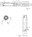
- FIG. 1 shows a syringe with a cartridge 1, the front end portion is covered by a detachable cap 2.
- a flexible inner bag 3 is molded, which includes a bottom wall 4, which is considerably thicker than the cylindrical wall of the inner bag.
- a piston 5 of the syringe which is advanceable to eject the contents of the cartridge.
- two mandrels are inserted into the cartridge, wherein between the peripheral wall of the upper mandrel (according FIG. 3 ) and the inner wall of the cartridge and between the underside of the upper mold core and the upper side of a lower mold core, the material of the inner bag is injected, which does not enter into communication with the cartridge.
- the injection mold is designed so that the material of the inner bag also enters an upper annular groove 6 of the cartridge, so that the inner bag is fixed to the cartridge 1 here.
Landscapes
- Engineering & Computer Science (AREA)
- Manufacturing & Machinery (AREA)
- Mechanical Engineering (AREA)
- Injection Moulding Of Plastics Or The Like (AREA)
- Moulds For Moulding Plastics Or The Like (AREA)
- Medical Preparation Storing Or Oral Administration Devices (AREA)
- Containers And Packaging Bodies Having A Special Means To Remove Contents (AREA)
- Infusion, Injection, And Reservoir Apparatuses (AREA)
Description
Verfahren zur Herstellung eines Behälters mit einem flexiblen InnenbeutelMethod for producing a container with a flexible inner bag
Die Erfindung betrifft ein Verfahren zur Herstellung eines Behälters mit einem flexiblen Innenbeutel.The invention relates to a method for producing a container with a flexible inner bag.
Der Behälter hat ein bodenloses, offenes Ende, in das ein Kolben eingreift, der vorgeschoben wird, um Behälterinhalt aus dem flexiblen Innenbeutel auszudrücken. Der Behälter bildet mit seinem Innenbeutel eine Kartusche einer Spritze.The container has a bottomless, open end into which a piston which is advanced to express container contents from the flexible inner bag engages. The container forms with its inner bag a cartridge of a syringe.
Ein Herstellungsverfahren für einen Behälter mit einem darin angeordneten flexiblen Innenbeutel ist aus der
Die
Der vorliegenden Erfindung liegt die Aufgabe zugrunde, ein Verfahren zur Herstellung eine Spritzenkartusche mit einem flexiblen Innenbeutel anzugeben, bei der das aufwendige Koextrusionsverfahren und eine sichtbare Naht am Boden des Behälters vermieden sind.The present invention has for its object to provide a method for producing a syringe cartridge with a flexible inner bag, in which the complex coextrusion process and a visible seam at the bottom of the container are avoided.
Diese Aufgabe wird erfindungsgemäß durch die im Patentanspruch 1 angegebenen Verfahrensschritte gelöst. Vorteilhafte Ausgestaltungen der Erfindung sind in den abhängigen Ansprüche gekennzeichnet.This object is achieved by the method steps indicated in
Das erfindungsgemäße Verfahren sieht vor, dass zunächst ein Behälter ohne Bodenwand aus einem ersten Kunststoffmaterial hergestellt wird. Hierzu kommt jedes geeignete Verfahren, beispielsweise Blasverfahren oder Spritzgussverfahren in Betracht.The inventive method provides that initially a container without bottom wall is made of a first plastic material. For this purpose, any suitable method, for example blow molding or injection molding into consideration.
Anschließend wird der Behälter in einer Spritzgussform angeordnet, und es wird ein Formkern derart in den Behälter eingesetzt, dass ein Ringspalt zwischen dem Formkern und der Innenwand des Behälters verbleibt und außerdem unter oder hinter dem Ende des Formkerns ein Hohlraum frei von dem Formkern bleibt. Durch geeignete Maßnahmen wird vorzugsweise sichergestellt, dass der Formkern sich mittig in dem Behälter befindet:Subsequently, the container is placed in an injection mold, and a mold core is inserted into the container such that an annular gap remains between the mold core and the inner wall of the container and also below or behind the end of the mold core, a cavity remains free from the mold core. By suitable measures is preferably ensured that the mandrel is located centrally in the container:
Der Ringspalt kann in Umfangsrichtung und/oder in axialer Richtung eine konstante Breite haben. Die Breite des Ringspalts kann bis zu 0,5 mm, vorzugsweise nur bis zu 0,2 mm betragen.The annular gap may have a constant width in the circumferential direction and / or in the axial direction. The width of the annular gap can be up to 0.5 mm, preferably only up to 0.2 mm.
Anschließend wird die Spritzgussform geschlossen und ein zweites Material, das keine Verbindung mit dem ersten Material des Behälters eingeht, in den Ringspalt und den unter dem Ende des Formkerns verbliebenen Hohlraum gespritzt. Hierdurch wird der flexible Innenbeutel erzeugt, der an der Innenwand des Behälters anliegt, jedoch mit diesem keine Verbindung eingeht und daher leicht von dem Behälter ablösbar ist.Subsequently, the injection mold is closed and a second material, which does not enter into communication with the first material of the container, injected into the annular gap and remaining under the end of the mandrel cavity. As a result, the flexible inner bag is produced, which rests against the inner wall of the container, but does not enter into contact with it and is therefore easily detachable from the container.
Nach dem Öffnen der Spritzgussform und dem Zurückziehen des Formkerns aus dem Behälter kann dieser mit dem anliegenden Innenbeutel entnommen werden.After opening the injection mold and retracting the mandrel from the container, it can be removed with the adjacent inner bag.
Dieses Verfahren ermöglicht es, Innenbeutel mit der jeweils gewünschten Wandstärke und Wandstärkenverteilung mit verhältnismäßig geringem Aufwand herzustellen, indem die Außenkontur des in den Behälter eingesetzten Formkerns entsprechend gestaltet wird.This method makes it possible to produce inner bag with the respective desired wall thickness and wall thickness distribution with relatively little effort by the outer contour of the mold core inserted into the container is designed accordingly.
In einer Ausführungsform der Erfindung wird der Behälter mit einer kreiszylindrischen Innenwand hergestellt. Wenn der zugehörige Formkern ebenfalls eine kreiszylindrische Form hat, wird auf diese Weise ein flexibler Innenbeutel mit in Umfangsrichtung und in axialer Richtung gleichbleibender Wandstärke erzeugt.In one embodiment of the invention, the container is manufactured with a circular cylindrical inner wall. If the associated mandrel also has a circular cylindrical shape, a flexible inner bag is produced in this way with a constant wall thickness in the circumferential direction and in the axial direction.
Der Behälter kann sich jedoch auch zu seinem oberen Ende hin erweitern, was das Zurückziehen des Formkerns dann erleichtert, wenn dieser eine kreiszylindrische Form hat. Bei dieser Ausführungsform der Erfindung nimmt die Wandstärke des Innenbeutels zur Austrittsöffnung des Behälters hin zu. Der Behälter und/oder der Formkern können auch in Umfangsrichtung eine von einem Kreiszylinder abweichende Kontur haben, beispielsweise kann auf diese Weise ein Innenbeutel hergestellt werden, der in axialer Richtung verlaufende Wandstreifen kleineren oder größeren Durchmessers hat, damit sich der Innenbeutel bei der Abgabe von Behälterinhalt auf eine gewünschte Weise zusammenziehen kann, damit eine evtl. nicht ausbringbare Restmenge des Behälterinhalts minimiert wird.However, the container may also expand toward its upper end, which facilitates retraction of the mandrel when it has a circular cylindrical shape. In this embodiment of the invention, the wall thickness of the inner bag increases toward the outlet opening of the container. The container and / or the mandrel may also have in the circumferential direction deviating from a circular cylinder contour, for example, in this way an inner bag can be made, which has smaller or larger diameter in the axial direction wall strips, so that the inner bag in the delivery of container contents can contract in a desired manner, so that a possibly nichtbringbringbare residual amount of the container contents is minimized.
Außerdem ist vorgesehen, dass der Behälter im Bereich der Austrittsöffnung des Behälterinhalts eine vorzugsweise hinterschnittene Ringnut hat, in die beim Spritzgießen ebenfalls das Material des flexiblen Innenbeutels eintritt, wodurch vorzugsweise dieser fest mit dem Behälter verbunden wird.It is also provided that the container in the region of the outlet opening of the container contents has a preferably undercut annular groove, in which the material of the flexible inner bag also enters during injection molding, whereby preferably this is firmly connected to the container.
Wenn der Behälterinhalt mit der Umgebungsluft in Berührung kommen darf, kann der Behälterinhalt durch eine Pumpe abgegeben werden, die den Eintritt von Luft in den Innenbeutel zulässt.If the container contents are allowed to come into contact with the ambient air, the contents of the container may be dispensed by a pump which allows air to enter the inner bag.
Erfindungsgemäß wird ein Behälter ohne Bodenwand verwendet, wobei die Spritzgussform so gestaltet ist, dass sie beim Spritzgussvorgang den offenen Boden des Behälters verschließt. Auf diese Weise ist eine Kartusche für eine Spritze herstellbar, bei der ein Kolben in das offene Ende des Behälters eingreift und zur Abgabe von Behälterinhalt in dem Behälter vorgeschoben wird und dabei den Innenbeutel in Richtung der Austrittsöffnung des Behälterinhalts drückt. Der Innenbeutel hat bevorzugt eine kreiszylindrische Form mit konstanter Wandstärke der Umfangswand, jedoch hat die Bodenwand des Innenbeutels bevorzugt eine größere Wandstärke, um dem Druck des Kolbens besser standhalten zu können.According to the invention, a container without bottom wall is used, wherein the injection mold is designed so that it closes the open bottom of the container during the injection molding process. In this way, a cartridge for a syringe can be produced, in which a piston engages in the open end of the container and is advanced for dispensing container contents in the container, thereby pressing the inner bag in the direction of the outlet opening of the container contents. The inner bag preferably has a circular cylindrical shape with a constant wall thickness of the circumferential wall, but preferably the bottom wall of the inner bag has a greater wall thickness in order to better withstand the pressure of the piston.
Bei der Verwendung als Kartusche einer Spritze hat der flexible Innenbeutel nur eine geringe Wandstärke von maximal 0,5 mm, wobei eine Wandstärke von etwa 0,2 mm bevorzugt ist.When used as a cartridge of a syringe of flexible inner bag has only a small wall thickness of a maximum of 0.5 mm, with a wall thickness of about 0.2 mm is preferred.
Wie oben erwähnt ist, werden bei dem erfindungsgemäßen Verfahren für den Behälter und den Innenbeutel zwei verschiedene Materialien verwendet, die keine Verbindung miteinander eingehen, so dass der Innenbeutel leicht ablösbar ist. Wenn - wie dies bevorzugt ist - der Behälter z. B. aus PP, COP oder COC besteht, kommen für das Material des Innenbeutels PE, Solyn, EVA oder PA in Betracht, ohne dass diese Aufzählung abschließend ist. Damit sich der Innenbeutel leicht von dem Behälter lösen lässt, sollte die Innenwand des Behälters eine glatte Kontur haben, wie dies bei einem Kreiszylinder oder einem Zylinder mit ovaler Querschnittsform der Fall ist.As mentioned above, in the method according to the invention for the container and the inner bag, two different materials are used, which do not communicate with each other, so that the inner bag is easily detachable. If - as is preferred - the container z. B. PP, COP or COC, come for the material of the inner bag PE, Solyn, EVA or PA into consideration, without this list is exhaustive. In order for the inner bag to be easily detached from the container, the inner wall of the container should have a smooth contour, as is the case with a circular cylinder or a cylinder with an oval cross-sectional shape.
Die Erfindung wird nachfolgend anhand einer Ausführungsform mit Bezug auf die beigefügten Zeichnungen näher erläutert. Dabei zeigen:
Figur 1- einen Längsschnitt durch eine Spritze mit einer Kartusche, die nach dem erfindungsgemäßen Verfahren mit einem flexiblen Innenbeutel versehen ist;
Figur 2- eine Aufsicht auf die Kartusche der
Figur 1 Figur 3- Schnitt A-A der
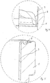
Figur 2 Figur 4- die Einzelheit C der
Figur 3 Figur 5- die Einzelheit B der
Figur 3
- FIG. 1
- a longitudinal section through a syringe with a cartridge, which is provided by the method according to the invention with a flexible inner bag;
- FIG. 2
- a top view of the cartridge of the
FIG. 1 ; - FIG. 3
- Cut AA the
FIG. 2 ; - FIG. 4
- the detail C of
FIG. 3 in an enlarged view and - FIG. 5
- the detail B of
FIG. 3 in an enlarged view.
Zur Ausbildung des Innenbeutels werden zwei Formkerne in die Kartusche eingesetzt, wobei zwischen die Umfangswand des oberen Formkerns (gemäß
Die Spritzgussform ist so gestaltet, dass das Material des Innenbeutels auch in eine obere Ringnut 6 der Kartusche eintritt, so dass der Innenbeutel hier an der Kartusche 1 fixiert ist.The injection mold is designed so that the material of the inner bag also enters an upper annular groove 6 of the cartridge, so that the inner bag is fixed to the
Herkömmliche Spritzkartuschen werden durch einen gummiartigen Kolben abgedichtet, der unter Vorspannung an der Innenwand der Kartusche anliegt. Dies kann zu Problemen mit der Abdichtung führen. Außerdem muss beim Vorschub die auftretende Reibungskraft überwunden werden und es tritt häufig ein Nachtropfen des Kartuscheninhalts auf. Diese Nachteile sind bei der erfindungsgemäßen Kartusche vermieden.Conventional syringe cartridges are sealed by a rubber-like piston biased against the inner wall of the cartridge. This can lead to problems with the seal. In addition, the friction occurring in the feed must be overcome and there is often a dripping of the cartridge contents. These disadvantages are avoided in the cartridge according to the invention.
Claims (7)
- A method of manufacturing a syringe cartridge with a flexible inner bag, the content of which is dischargeable by the advance of a syringe piston (5), characterised by the following steps:a) producing a substantially cylindrical container (1) without a base wall from a first plastic material, wherein at least one annular groove (6) is formed at the front edge of the container;b) arranging the container (1) in an injection mould, wherein the injection mould closes the open base of the container (1);c) inserting a mould core of a smaller diameter into the container (1) such that an annular gap between the mould core and the inner wall and a cavity at the end of the mould core remain;d) closing the injection mould and injecting a second material for the inner bag (3), which forms no connection with the first material, into the annular gap, the at least one annular groove (6) and the cavity;e) opening the injection mould, retracting the mould core from the container and removing the container (1) with an attached inner bag (3).
- A method as claimed in Claim 1, characterised in that the container (1) is produced with a circular cylindrical inner wall.
- A method as claimed in Claim 1 or 2, characterised in that a mould core with a circular cylindrical shape is used.
- A method as claimed in one of Claims 1 to 3, characterised in that the annular gap has a constant breadth in the peripheral direction.
- A method as claimed in one of Claims 1 to 4, characterised in that the annular gap has a constant breadth in the axial direction.
- A method as claimed in one of Claims 1 to 5, characterised in that the breadth of the annular gap is up to 0.5 mm, preferably only up to 0.2 mm.
- A method as claimed in one of Claims 1 to 6, characterised in that the inner bag (3) has a circular cylindrical shape with constant wall thickness of the peripheral wall and that its base wall (4) is thicker than its peripheral wall.
Applications Claiming Priority (1)
| Application Number | Priority Date | Filing Date | Title |
|---|---|---|---|
| DE102013008088.6A DE102013008088B4 (en) | 2013-05-10 | 2013-05-10 | Method for producing a syringe cartridge with a flexible inner bag |
Publications (3)
| Publication Number | Publication Date |
|---|---|
| EP2801465A2 EP2801465A2 (en) | 2014-11-12 |
| EP2801465A3 EP2801465A3 (en) | 2016-02-17 |
| EP2801465B1 true EP2801465B1 (en) | 2017-01-04 |
Family
ID=50238092
Family Applications (1)
| Application Number | Title | Priority Date | Filing Date |
|---|---|---|---|
| EP14000797.2A Active EP2801465B1 (en) | 2013-05-10 | 2014-03-06 | Method for producing a container with a flexible inner bag |
Country Status (2)
| Country | Link |
|---|---|
| EP (1) | EP2801465B1 (en) |
| DE (1) | DE102013008088B4 (en) |
Families Citing this family (2)
| Publication number | Priority date | Publication date | Assignee | Title |
|---|---|---|---|---|
| US10472162B2 (en) | 2016-09-09 | 2019-11-12 | The Clorox Company | Continuous spray dispenser for highly corrosive and other low compatibility products |
| DE102017004657B4 (en) | 2017-05-16 | 2021-09-23 | Gaplast Gmbh | Container with inner bag |
Family Cites Families (10)
| Publication number | Priority date | Publication date | Assignee | Title |
|---|---|---|---|---|
| DE1108421B (en) * | 1955-05-02 | 1961-06-08 | Maurice Raphael Bassan | Injection mold for the production of tubes made of thermoplastic material |
| DE4139555A1 (en) * | 1991-09-18 | 1993-03-25 | Gaplast Gmbh | CONTAINER |
| US5405056A (en) * | 1994-04-01 | 1995-04-11 | Mills; Gregory B. | Stereo dispensing container and system |
| DE19626967C2 (en) | 1996-07-04 | 1999-08-12 | Gaplast Gmbh | Process for producing a container and containers with pressure equalization openings |
| WO2001026881A1 (en) * | 1999-10-08 | 2001-04-19 | Taisei Kako Co., Ltd. | Method of producing laminated bottles having peelable inner layer |
| JP4485627B2 (en) * | 1999-10-08 | 2010-06-23 | 大成化工株式会社 | Laminated peeling bottle and pump container |
| DE10256015B4 (en) | 2002-11-30 | 2005-04-14 | Gaplast Gmbh | Method for producing a container with at least one pressure equalization opening |
| JP4357183B2 (en) * | 2003-02-14 | 2009-11-04 | 大成化工株式会社 | Delaminated bottle and method for producing the same |
| DE102005017599A1 (en) * | 2005-04-16 | 2006-10-19 | Fischerwerke Artur Fischer Gmbh & Co. Kg | Multicomponent cartridge |
| DE102011100078A1 (en) * | 2011-04-29 | 2012-10-31 | Netstal-Maschinen Ag | Method for manufacturing plastic container coated with plastic material for food product, involves providing film or film body in specific areas with reinforcement in regions, which are exposed to high mechanical load during molding process |
-
2013
- 2013-05-10 DE DE102013008088.6A patent/DE102013008088B4/en active Active
-
2014
- 2014-03-06 EP EP14000797.2A patent/EP2801465B1/en active Active
Non-Patent Citations (1)
| Title |
|---|
| None * |
Also Published As
| Publication number | Publication date |
|---|---|
| DE102013008088B4 (en) | 2016-02-18 |
| DE102013008088A1 (en) | 2014-11-13 |
| EP2801465A3 (en) | 2016-02-17 |
| EP2801465A2 (en) | 2014-11-12 |
Similar Documents
| Publication | Publication Date | Title |
|---|---|---|
| DE69630822T2 (en) | Device and method for delaminating a container made of laminated material | |
| EP1894702B1 (en) | Method for manufacturing a fuel container | |
| DE1604653A1 (en) | Plastic container, process for its manufacture and device for carrying out the process | |
| DE9219211U1 (en) | container | |
| EP0182094A2 (en) | Method for making a container with a sealable opening, and container obtained thereby | |
| DE2353209A1 (en) | DEEP-DRAWN CONTAINER AND PROCESS FOR ITS MANUFACTURING | |
| DE102009031441A1 (en) | Method for producing an article made of thermoplastic material | |
| DE3134602C2 (en) | Method and device for producing a tube with a closure cap made of plastic | |
| DE10105699A1 (en) | Method and device for producing a diffusion-tight plastic container | |
| DE1299406B (en) | Method and apparatus for making bottles and. Like. Hollow bodies made of thermoformable plastics | |
| EP3487790B1 (en) | Waste water container, method for the production thereof | |
| EP1082204B2 (en) | Method and device for producing plastic hollow bodies | |
| WO1995003231A1 (en) | Pallet container | |
| EP0189750A2 (en) | Method of making hollow bodies with multi-layered walls | |
| EP2801465B1 (en) | Method for producing a container with a flexible inner bag | |
| DE69218610T2 (en) | STORAGE HEAD FOR EXTRUSION BLOW MOLDING MACHINE | |
| DE69627824T2 (en) | METHOD AND DEVICE FOR PRODUCING TUBULAR CONTAINERS WITH LOCKING DEVICE | |
| DE69423536T2 (en) | Method and device for producing a holding flange around a container opening | |
| EP0867374B1 (en) | Process to produce a multicompartment tube container | |
| EP3291961B1 (en) | Method and device for producing large volume containers with a flange by plastic blow molding | |
| DE2149569B2 (en) | Device for producing a canister with two cells separated from one another | |
| DE3719252A1 (en) | Dispenser for delivering pasty substances | |
| DE60022571T2 (en) | Tubular hollow body for pasty products and manufacturing processes | |
| EP0626248B1 (en) | Hollow mould for manufacturing hollow bodies with handles | |
| EP4514588B1 (en) | Dispenser container and method for producing a dispenser container |
Legal Events
| Date | Code | Title | Description |
|---|---|---|---|
| PUAI | Public reference made under article 153(3) epc to a published international application that has entered the european phase |
Free format text: ORIGINAL CODE: 0009012 |
|
| 17P | Request for examination filed |
Effective date: 20140306 |
|
| AK | Designated contracting states |
Kind code of ref document: A2 Designated state(s): AL AT BE BG CH CY CZ DE DK EE ES FI FR GB GR HR HU IE IS IT LI LT LU LV MC MK MT NL NO PL PT RO RS SE SI SK SM TR |
|
| AX | Request for extension of the european patent |
Extension state: BA ME |
|
| RIN1 | Information on inventor provided before grant (corrected) |
Inventor name: KNEER, ROLAND Inventor name: KNEER, STEPHAN |
|
| RIC1 | Information provided on ipc code assigned before grant |
Ipc: B29L 31/00 20060101ALN20150630BHEP Ipc: B29C 45/14 20060101AFI20150630BHEP Ipc: B29C 45/16 20060101ALN20150630BHEP Ipc: B29C 45/26 20060101ALN20150630BHEP Ipc: B65D 1/02 20060101ALN20150630BHEP Ipc: B65D 83/00 20060101ALN20150630BHEP |
|
| PUAL | Search report despatched |
Free format text: ORIGINAL CODE: 0009013 |
|
| AK | Designated contracting states |
Kind code of ref document: A3 Designated state(s): AL AT BE BG CH CY CZ DE DK EE ES FI FR GB GR HR HU IE IS IT LI LT LU LV MC MK MT NL NO PL PT RO RS SE SI SK SM TR |
|
| AX | Request for extension of the european patent |
Extension state: BA ME |
|
| R17P | Request for examination filed (corrected) |
Effective date: 20151229 |
|
| RBV | Designated contracting states (corrected) |
Designated state(s): AL AT BE BG CH CY CZ DE DK EE ES FI FR GB GR HR HU IE IS IT LI LT LU LV MC MK MT NL NO PL PT RO RS SE SI SK SM TR |
|
| RIC1 | Information provided on ipc code assigned before grant |
Ipc: B65D 1/02 20060101ALN20160112BHEP Ipc: B29C 45/26 20060101ALN20160112BHEP Ipc: B29L 31/00 20060101ALN20160112BHEP Ipc: B65D 83/00 20060101ALN20160112BHEP Ipc: B29C 45/16 20060101ALN20160112BHEP Ipc: B29C 45/14 20060101AFI20160112BHEP |
|
| RIN1 | Information on inventor provided before grant (corrected) |
Inventor name: KNEER, STEPHAN Inventor name: KNEER, ROLAND |
|
| 17Q | First examination report despatched |
Effective date: 20160615 |
|
| GRAP | Despatch of communication of intention to grant a patent |
Free format text: ORIGINAL CODE: EPIDOSNIGR1 |
|
| RIC1 | Information provided on ipc code assigned before grant |
Ipc: B65D 1/02 20060101ALN20160928BHEP Ipc: B29L 31/00 20060101ALN20160928BHEP Ipc: B65D 83/00 20060101ALN20160928BHEP Ipc: B29C 45/26 20060101ALN20160928BHEP Ipc: B29C 45/16 20060101ALN20160928BHEP Ipc: B29C 45/14 20060101AFI20160928BHEP |
|
| INTG | Intention to grant announced |
Effective date: 20161018 |
|
| GRAS | Grant fee paid |
Free format text: ORIGINAL CODE: EPIDOSNIGR3 |
|
| GRAA | (expected) grant |
Free format text: ORIGINAL CODE: 0009210 |
|
| AK | Designated contracting states |
Kind code of ref document: B1 Designated state(s): AL AT BE BG CH CY CZ DE DK EE ES FI FR GB GR HR HU IE IS IT LI LT LU LV MC MK MT NL NO PL PT RO RS SE SI SK SM TR |
|
| REG | Reference to a national code |
Ref country code: GB Ref legal event code: FG4D Free format text: NOT ENGLISH |
|
| REG | Reference to a national code |
Ref country code: CH Ref legal event code: EP |
|
| REG | Reference to a national code |
Ref country code: AT Ref legal event code: REF Ref document number: 858797 Country of ref document: AT Kind code of ref document: T Effective date: 20170115 |
|
| REG | Reference to a national code |
Ref country code: IE Ref legal event code: FG4D Free format text: LANGUAGE OF EP DOCUMENT: GERMAN |
|
| REG | Reference to a national code |
Ref country code: CH Ref legal event code: NV Representative=s name: KIRKER AND CIE S.A., CH |
|
| REG | Reference to a national code |
Ref country code: DE Ref legal event code: R096 Ref document number: 502014002359 Country of ref document: DE |
|
| REG | Reference to a national code |
Ref country code: FR Ref legal event code: PLFP Year of fee payment: 4 |
|
| REG | Reference to a national code |
Ref country code: LT Ref legal event code: MG4D Ref country code: NL Ref legal event code: MP Effective date: 20170104 |
|
| PG25 | Lapsed in a contracting state [announced via postgrant information from national office to epo] |
Ref country code: NL Free format text: LAPSE BECAUSE OF FAILURE TO SUBMIT A TRANSLATION OF THE DESCRIPTION OR TO PAY THE FEE WITHIN THE PRESCRIBED TIME-LIMIT Effective date: 20170104 |
|
| PG25 | Lapsed in a contracting state [announced via postgrant information from national office to epo] |
Ref country code: IS Free format text: LAPSE BECAUSE OF FAILURE TO SUBMIT A TRANSLATION OF THE DESCRIPTION OR TO PAY THE FEE WITHIN THE PRESCRIBED TIME-LIMIT Effective date: 20170504 Ref country code: HR Free format text: LAPSE BECAUSE OF FAILURE TO SUBMIT A TRANSLATION OF THE DESCRIPTION OR TO PAY THE FEE WITHIN THE PRESCRIBED TIME-LIMIT Effective date: 20170104 Ref country code: GR Free format text: LAPSE BECAUSE OF FAILURE TO SUBMIT A TRANSLATION OF THE DESCRIPTION OR TO PAY THE FEE WITHIN THE PRESCRIBED TIME-LIMIT Effective date: 20170405 Ref country code: FI Free format text: LAPSE BECAUSE OF FAILURE TO SUBMIT A TRANSLATION OF THE DESCRIPTION OR TO PAY THE FEE WITHIN THE PRESCRIBED TIME-LIMIT Effective date: 20170104 Ref country code: NO Free format text: LAPSE BECAUSE OF FAILURE TO SUBMIT A TRANSLATION OF THE DESCRIPTION OR TO PAY THE FEE WITHIN THE PRESCRIBED TIME-LIMIT Effective date: 20170404 Ref country code: LT Free format text: LAPSE BECAUSE OF FAILURE TO SUBMIT A TRANSLATION OF THE DESCRIPTION OR TO PAY THE FEE WITHIN THE PRESCRIBED TIME-LIMIT Effective date: 20170104 |
|
| PG25 | Lapsed in a contracting state [announced via postgrant information from national office to epo] |
Ref country code: PL Free format text: LAPSE BECAUSE OF FAILURE TO SUBMIT A TRANSLATION OF THE DESCRIPTION OR TO PAY THE FEE WITHIN THE PRESCRIBED TIME-LIMIT Effective date: 20170104 Ref country code: LV Free format text: LAPSE BECAUSE OF FAILURE TO SUBMIT A TRANSLATION OF THE DESCRIPTION OR TO PAY THE FEE WITHIN THE PRESCRIBED TIME-LIMIT Effective date: 20170104 Ref country code: RS Free format text: LAPSE BECAUSE OF FAILURE TO SUBMIT A TRANSLATION OF THE DESCRIPTION OR TO PAY THE FEE WITHIN THE PRESCRIBED TIME-LIMIT Effective date: 20170104 Ref country code: BG Free format text: LAPSE BECAUSE OF FAILURE TO SUBMIT A TRANSLATION OF THE DESCRIPTION OR TO PAY THE FEE WITHIN THE PRESCRIBED TIME-LIMIT Effective date: 20170404 Ref country code: ES Free format text: LAPSE BECAUSE OF FAILURE TO SUBMIT A TRANSLATION OF THE DESCRIPTION OR TO PAY THE FEE WITHIN THE PRESCRIBED TIME-LIMIT Effective date: 20170104 Ref country code: PT Free format text: LAPSE BECAUSE OF FAILURE TO SUBMIT A TRANSLATION OF THE DESCRIPTION OR TO PAY THE FEE WITHIN THE PRESCRIBED TIME-LIMIT Effective date: 20170504 Ref country code: SE Free format text: LAPSE BECAUSE OF FAILURE TO SUBMIT A TRANSLATION OF THE DESCRIPTION OR TO PAY THE FEE WITHIN THE PRESCRIBED TIME-LIMIT Effective date: 20170104 |
|
| REG | Reference to a national code |
Ref country code: DE Ref legal event code: R097 Ref document number: 502014002359 Country of ref document: DE |
|
| PG25 | Lapsed in a contracting state [announced via postgrant information from national office to epo] |
Ref country code: CZ Free format text: LAPSE BECAUSE OF FAILURE TO SUBMIT A TRANSLATION OF THE DESCRIPTION OR TO PAY THE FEE WITHIN THE PRESCRIBED TIME-LIMIT Effective date: 20170104 Ref country code: RO Free format text: LAPSE BECAUSE OF FAILURE TO SUBMIT A TRANSLATION OF THE DESCRIPTION OR TO PAY THE FEE WITHIN THE PRESCRIBED TIME-LIMIT Effective date: 20170104 Ref country code: SK Free format text: LAPSE BECAUSE OF FAILURE TO SUBMIT A TRANSLATION OF THE DESCRIPTION OR TO PAY THE FEE WITHIN THE PRESCRIBED TIME-LIMIT Effective date: 20170104 Ref country code: EE Free format text: LAPSE BECAUSE OF FAILURE TO SUBMIT A TRANSLATION OF THE DESCRIPTION OR TO PAY THE FEE WITHIN THE PRESCRIBED TIME-LIMIT Effective date: 20170104 |
|
| PLBE | No opposition filed within time limit |
Free format text: ORIGINAL CODE: 0009261 |
|
| STAA | Information on the status of an ep patent application or granted ep patent |
Free format text: STATUS: NO OPPOSITION FILED WITHIN TIME LIMIT |
|
| PG25 | Lapsed in a contracting state [announced via postgrant information from national office to epo] |
Ref country code: DK Free format text: LAPSE BECAUSE OF FAILURE TO SUBMIT A TRANSLATION OF THE DESCRIPTION OR TO PAY THE FEE WITHIN THE PRESCRIBED TIME-LIMIT Effective date: 20170104 Ref country code: MC Free format text: LAPSE BECAUSE OF FAILURE TO SUBMIT A TRANSLATION OF THE DESCRIPTION OR TO PAY THE FEE WITHIN THE PRESCRIBED TIME-LIMIT Effective date: 20170104 Ref country code: SM Free format text: LAPSE BECAUSE OF FAILURE TO SUBMIT A TRANSLATION OF THE DESCRIPTION OR TO PAY THE FEE WITHIN THE PRESCRIBED TIME-LIMIT Effective date: 20170104 |
|
| REG | Reference to a national code |
Ref country code: IE Ref legal event code: MM4A |
|
| PG25 | Lapsed in a contracting state [announced via postgrant information from national office to epo] |
Ref country code: LU Free format text: LAPSE BECAUSE OF NON-PAYMENT OF DUE FEES Effective date: 20170306 |
|
| REG | Reference to a national code |
Ref country code: FR Ref legal event code: PLFP Year of fee payment: 5 |
|
| PG25 | Lapsed in a contracting state [announced via postgrant information from national office to epo] |
Ref country code: SI Free format text: LAPSE BECAUSE OF FAILURE TO SUBMIT A TRANSLATION OF THE DESCRIPTION OR TO PAY THE FEE WITHIN THE PRESCRIBED TIME-LIMIT Effective date: 20170104 Ref country code: IE Free format text: LAPSE BECAUSE OF NON-PAYMENT OF DUE FEES Effective date: 20170306 |
|
| REG | Reference to a national code |
Ref country code: BE Ref legal event code: MM Effective date: 20170331 |
|
| PG25 | Lapsed in a contracting state [announced via postgrant information from national office to epo] |
Ref country code: BE Free format text: LAPSE BECAUSE OF NON-PAYMENT OF DUE FEES Effective date: 20170331 |
|
| PG25 | Lapsed in a contracting state [announced via postgrant information from national office to epo] |
Ref country code: MT Free format text: LAPSE BECAUSE OF FAILURE TO SUBMIT A TRANSLATION OF THE DESCRIPTION OR TO PAY THE FEE WITHIN THE PRESCRIBED TIME-LIMIT Effective date: 20170104 |
|
| PG25 | Lapsed in a contracting state [announced via postgrant information from national office to epo] |
Ref country code: HU Free format text: LAPSE BECAUSE OF FAILURE TO SUBMIT A TRANSLATION OF THE DESCRIPTION OR TO PAY THE FEE WITHIN THE PRESCRIBED TIME-LIMIT; INVALID AB INITIO Effective date: 20140306 |
|
| PG25 | Lapsed in a contracting state [announced via postgrant information from national office to epo] |
Ref country code: CY Free format text: LAPSE BECAUSE OF FAILURE TO SUBMIT A TRANSLATION OF THE DESCRIPTION OR TO PAY THE FEE WITHIN THE PRESCRIBED TIME-LIMIT Effective date: 20170104 |
|
| PG25 | Lapsed in a contracting state [announced via postgrant information from national office to epo] |
Ref country code: MK Free format text: LAPSE BECAUSE OF FAILURE TO SUBMIT A TRANSLATION OF THE DESCRIPTION OR TO PAY THE FEE WITHIN THE PRESCRIBED TIME-LIMIT Effective date: 20170104 |
|
| PG25 | Lapsed in a contracting state [announced via postgrant information from national office to epo] |
Ref country code: TR Free format text: LAPSE BECAUSE OF FAILURE TO SUBMIT A TRANSLATION OF THE DESCRIPTION OR TO PAY THE FEE WITHIN THE PRESCRIBED TIME-LIMIT Effective date: 20170104 |
|
| PG25 | Lapsed in a contracting state [announced via postgrant information from national office to epo] |
Ref country code: AL Free format text: LAPSE BECAUSE OF FAILURE TO SUBMIT A TRANSLATION OF THE DESCRIPTION OR TO PAY THE FEE WITHIN THE PRESCRIBED TIME-LIMIT Effective date: 20170104 |
|
| REG | Reference to a national code |
Ref country code: AT Ref legal event code: MM01 Ref document number: 858797 Country of ref document: AT Kind code of ref document: T Effective date: 20190306 |
|
| PG25 | Lapsed in a contracting state [announced via postgrant information from national office to epo] |
Ref country code: AT Free format text: LAPSE BECAUSE OF NON-PAYMENT OF DUE FEES Effective date: 20190306 |
|
| P01 | Opt-out of the competence of the unified patent court (upc) registered |
Effective date: 20230512 |
|
| PGFP | Annual fee paid to national office [announced via postgrant information from national office to epo] |
Ref country code: FR Payment date: 20250212 Year of fee payment: 12 |
|
| PGFP | Annual fee paid to national office [announced via postgrant information from national office to epo] |
Ref country code: GB Payment date: 20250212 Year of fee payment: 12 |
|
| PGFP | Annual fee paid to national office [announced via postgrant information from national office to epo] |
Ref country code: DE Payment date: 20250521 Year of fee payment: 12 |
|
| PGFP | Annual fee paid to national office [announced via postgrant information from national office to epo] |
Ref country code: IT Payment date: 20250331 Year of fee payment: 12 |
|
| PGFP | Annual fee paid to national office [announced via postgrant information from national office to epo] |
Ref country code: CH Payment date: 20250401 Year of fee payment: 12 |