EP0556552B1 - Method for producing hollow bodies from thermoplastic material and hollow body of thermoplastic material - Google Patents
Method for producing hollow bodies from thermoplastic material and hollow body of thermoplastic material Download PDFInfo
- Publication number
- EP0556552B1 EP0556552B1 EP93100355A EP93100355A EP0556552B1 EP 0556552 B1 EP0556552 B1 EP 0556552B1 EP 93100355 A EP93100355 A EP 93100355A EP 93100355 A EP93100355 A EP 93100355A EP 0556552 B1 EP0556552 B1 EP 0556552B1
- Authority
- EP
- European Patent Office
- Prior art keywords
- wall
- hollow body
- holding means
- process according
- additional body
- Prior art date
- Legal status (The legal status is an assumption and is not a legal conclusion. Google has not performed a legal analysis and makes no representation as to the accuracy of the status listed.)
- Expired - Lifetime
Links
- 238000004519 manufacturing process Methods 0.000 title claims description 6
- 239000012815 thermoplastic material Substances 0.000 title claims description 6
- 238000000034 method Methods 0.000 claims description 57
- 238000006073 displacement reaction Methods 0.000 claims description 14
- 238000000071 blow moulding Methods 0.000 claims description 13
- 239000000463 material Substances 0.000 claims description 12
- 239000012429 reaction media Substances 0.000 claims description 11
- 239000004033 plastic Substances 0.000 claims description 8
- 229920003023 plastic Polymers 0.000 claims description 8
- 239000012495 reaction gas Substances 0.000 claims description 7
- 230000000694 effects Effects 0.000 claims description 6
- 230000005489 elastic deformation Effects 0.000 claims description 3
- 229920000098 polyolefin Polymers 0.000 claims description 3
- 229920001169 thermoplastic Polymers 0.000 claims description 3
- 239000004416 thermosoftening plastic Substances 0.000 claims description 3
- 238000003466 welding Methods 0.000 claims description 3
- 239000000203 mixture Substances 0.000 claims description 2
- 239000000126 substance Substances 0.000 claims description 2
- 239000000470 constituent Substances 0.000 claims 1
- 229930195733 hydrocarbon Natural products 0.000 description 12
- 150000002430 hydrocarbons Chemical class 0.000 description 12
- 238000001125 extrusion Methods 0.000 description 7
- 239000002828 fuel tank Substances 0.000 description 7
- 239000000446 fuel Substances 0.000 description 6
- 239000007789 gas Substances 0.000 description 6
- 239000004698 Polyethylene Substances 0.000 description 4
- 238000007664 blowing Methods 0.000 description 4
- -1 polyethylene Polymers 0.000 description 4
- 229920000573 polyethylene Polymers 0.000 description 4
- 238000006243 chemical reaction Methods 0.000 description 3
- 230000035699 permeability Effects 0.000 description 3
- 239000002344 surface layer Substances 0.000 description 3
- 238000004381 surface treatment Methods 0.000 description 3
- YCKRFDGAMUMZLT-UHFFFAOYSA-N Fluorine atom Chemical compound [F] YCKRFDGAMUMZLT-UHFFFAOYSA-N 0.000 description 2
- 238000010101 extrusion blow moulding Methods 0.000 description 2
- 229910052731 fluorine Inorganic materials 0.000 description 2
- 239000011737 fluorine Substances 0.000 description 2
- 238000001746 injection moulding Methods 0.000 description 2
- 230000035515 penetration Effects 0.000 description 2
- 230000008961 swelling Effects 0.000 description 2
- OKTJSMMVPCPJKN-UHFFFAOYSA-N Carbon Chemical compound [C] OKTJSMMVPCPJKN-UHFFFAOYSA-N 0.000 description 1
- 229910000831 Steel Inorganic materials 0.000 description 1
- 239000000853 adhesive Substances 0.000 description 1
- 238000004026 adhesive bonding Methods 0.000 description 1
- 230000001070 adhesive effect Effects 0.000 description 1
- 230000015572 biosynthetic process Effects 0.000 description 1
- 229910052799 carbon Inorganic materials 0.000 description 1
- 238000001816 cooling Methods 0.000 description 1
- 238000010586 diagram Methods 0.000 description 1
- 238000003682 fluorination reaction Methods 0.000 description 1
- 239000011261 inert gas Substances 0.000 description 1
- 238000009434 installation Methods 0.000 description 1
- 239000007788 liquid Substances 0.000 description 1
- 230000000149 penetrating effect Effects 0.000 description 1
- 238000003825 pressing Methods 0.000 description 1
- 238000007711 solidification Methods 0.000 description 1
- 230000008023 solidification Effects 0.000 description 1
- 239000010959 steel Substances 0.000 description 1
- 238000006277 sulfonation reaction Methods 0.000 description 1
- 230000007704 transition Effects 0.000 description 1
Images


Classifications
-
- B—PERFORMING OPERATIONS; TRANSPORTING
- B29—WORKING OF PLASTICS; WORKING OF SUBSTANCES IN A PLASTIC STATE IN GENERAL
- B29C—SHAPING OR JOINING OF PLASTICS; SHAPING OF MATERIAL IN A PLASTIC STATE, NOT OTHERWISE PROVIDED FOR; AFTER-TREATMENT OF THE SHAPED PRODUCTS, e.g. REPAIRING
- B29C49/00—Blow-moulding, i.e. blowing a preform or parison to a desired shape within a mould; Apparatus therefor
- B29C49/42—Component parts, details or accessories; Auxiliary operations
- B29C49/46—Component parts, details or accessories; Auxiliary operations characterised by using particular environment or blow fluids other than air
-
- B—PERFORMING OPERATIONS; TRANSPORTING
- B29—WORKING OF PLASTICS; WORKING OF SUBSTANCES IN A PLASTIC STATE IN GENERAL
- B29C—SHAPING OR JOINING OF PLASTICS; SHAPING OF MATERIAL IN A PLASTIC STATE, NOT OTHERWISE PROVIDED FOR; AFTER-TREATMENT OF THE SHAPED PRODUCTS, e.g. REPAIRING
- B29C49/00—Blow-moulding, i.e. blowing a preform or parison to a desired shape within a mould; Apparatus therefor
- B29C49/02—Combined blow-moulding and manufacture of the preform or the parison
- B29C49/04—Extrusion blow-moulding
-
- B—PERFORMING OPERATIONS; TRANSPORTING
- B29—WORKING OF PLASTICS; WORKING OF SUBSTANCES IN A PLASTIC STATE IN GENERAL
- B29C—SHAPING OR JOINING OF PLASTICS; SHAPING OF MATERIAL IN A PLASTIC STATE, NOT OTHERWISE PROVIDED FOR; AFTER-TREATMENT OF THE SHAPED PRODUCTS, e.g. REPAIRING
- B29C49/00—Blow-moulding, i.e. blowing a preform or parison to a desired shape within a mould; Apparatus therefor
- B29C49/20—Blow-moulding, i.e. blowing a preform or parison to a desired shape within a mould; Apparatus therefor of articles having inserts or reinforcements ; Handling of inserts or reinforcements
-
- B—PERFORMING OPERATIONS; TRANSPORTING
- B60—VEHICLES IN GENERAL
- B60K—ARRANGEMENT OR MOUNTING OF PROPULSION UNITS OR OF TRANSMISSIONS IN VEHICLES; ARRANGEMENT OR MOUNTING OF PLURAL DIVERSE PRIME-MOVERS IN VEHICLES; AUXILIARY DRIVES FOR VEHICLES; INSTRUMENTATION OR DASHBOARDS FOR VEHICLES; ARRANGEMENTS IN CONNECTION WITH COOLING, AIR INTAKE, GAS EXHAUST OR FUEL SUPPLY OF PROPULSION UNITS IN VEHICLES
- B60K15/00—Arrangement in connection with fuel supply of combustion engines or other fuel consuming energy converters, e.g. fuel cells; Mounting or construction of fuel tanks
- B60K15/03—Fuel tanks
- B60K15/03177—Fuel tanks made of non-metallic material, e.g. plastics, or of a combination of non-metallic and metallic material
-
- B—PERFORMING OPERATIONS; TRANSPORTING
- B60—VEHICLES IN GENERAL
- B60K—ARRANGEMENT OR MOUNTING OF PROPULSION UNITS OR OF TRANSMISSIONS IN VEHICLES; ARRANGEMENT OR MOUNTING OF PLURAL DIVERSE PRIME-MOVERS IN VEHICLES; AUXILIARY DRIVES FOR VEHICLES; INSTRUMENTATION OR DASHBOARDS FOR VEHICLES; ARRANGEMENTS IN CONNECTION WITH COOLING, AIR INTAKE, GAS EXHAUST OR FUEL SUPPLY OF PROPULSION UNITS IN VEHICLES
- B60K15/00—Arrangement in connection with fuel supply of combustion engines or other fuel consuming energy converters, e.g. fuel cells; Mounting or construction of fuel tanks
- B60K15/03—Fuel tanks
- B60K15/077—Fuel tanks with means modifying or controlling distribution or motion of fuel, e.g. to prevent noise, surge, splash or fuel starvation
-
- B—PERFORMING OPERATIONS; TRANSPORTING
- B29—WORKING OF PLASTICS; WORKING OF SUBSTANCES IN A PLASTIC STATE IN GENERAL
- B29C—SHAPING OR JOINING OF PLASTICS; SHAPING OF MATERIAL IN A PLASTIC STATE, NOT OTHERWISE PROVIDED FOR; AFTER-TREATMENT OF THE SHAPED PRODUCTS, e.g. REPAIRING
- B29C49/00—Blow-moulding, i.e. blowing a preform or parison to a desired shape within a mould; Apparatus therefor
- B29C49/20—Blow-moulding, i.e. blowing a preform or parison to a desired shape within a mould; Apparatus therefor of articles having inserts or reinforcements ; Handling of inserts or reinforcements
- B29C2049/2008—Blow-moulding, i.e. blowing a preform or parison to a desired shape within a mould; Apparatus therefor of articles having inserts or reinforcements ; Handling of inserts or reinforcements inside the article
-
- B—PERFORMING OPERATIONS; TRANSPORTING
- B29—WORKING OF PLASTICS; WORKING OF SUBSTANCES IN A PLASTIC STATE IN GENERAL
- B29C—SHAPING OR JOINING OF PLASTICS; SHAPING OF MATERIAL IN A PLASTIC STATE, NOT OTHERWISE PROVIDED FOR; AFTER-TREATMENT OF THE SHAPED PRODUCTS, e.g. REPAIRING
- B29C49/00—Blow-moulding, i.e. blowing a preform or parison to a desired shape within a mould; Apparatus therefor
- B29C49/20—Blow-moulding, i.e. blowing a preform or parison to a desired shape within a mould; Apparatus therefor of articles having inserts or reinforcements ; Handling of inserts or reinforcements
- B29C2049/2073—Means for feeding the inserts into the mould, preform or parison, e.g. grippers
-
- B—PERFORMING OPERATIONS; TRANSPORTING
- B29—WORKING OF PLASTICS; WORKING OF SUBSTANCES IN A PLASTIC STATE IN GENERAL
- B29C—SHAPING OR JOINING OF PLASTICS; SHAPING OF MATERIAL IN A PLASTIC STATE, NOT OTHERWISE PROVIDED FOR; AFTER-TREATMENT OF THE SHAPED PRODUCTS, e.g. REPAIRING
- B29C49/00—Blow-moulding, i.e. blowing a preform or parison to a desired shape within a mould; Apparatus therefor
- B29C49/42—Component parts, details or accessories; Auxiliary operations
- B29C49/46—Component parts, details or accessories; Auxiliary operations characterised by using particular environment or blow fluids other than air
- B29C2049/4602—Blowing fluids
- B29C2049/4611—Blowing fluids containing a reactive gas
- B29C2049/4617—Fluor
-
- B—PERFORMING OPERATIONS; TRANSPORTING
- B29—WORKING OF PLASTICS; WORKING OF SUBSTANCES IN A PLASTIC STATE IN GENERAL
- B29C—SHAPING OR JOINING OF PLASTICS; SHAPING OF MATERIAL IN A PLASTIC STATE, NOT OTHERWISE PROVIDED FOR; AFTER-TREATMENT OF THE SHAPED PRODUCTS, e.g. REPAIRING
- B29C49/00—Blow-moulding, i.e. blowing a preform or parison to a desired shape within a mould; Apparatus therefor
- B29C49/42—Component parts, details or accessories; Auxiliary operations
- B29C49/46—Component parts, details or accessories; Auxiliary operations characterised by using particular environment or blow fluids other than air
- B29C2049/4602—Blowing fluids
- B29C2049/4611—Blowing fluids containing a reactive gas
- B29C2049/4623—Blowing fluids containing a reactive gas the gas containing sulfur, e.g. sulfur trioxide
-
- B—PERFORMING OPERATIONS; TRANSPORTING
- B29—WORKING OF PLASTICS; WORKING OF SUBSTANCES IN A PLASTIC STATE IN GENERAL
- B29K—INDEXING SCHEME ASSOCIATED WITH SUBCLASSES B29B, B29C OR B29D, RELATING TO MOULDING MATERIALS OR TO MATERIALS FOR MOULDS, REINFORCEMENTS, FILLERS OR PREFORMED PARTS, e.g. INSERTS
- B29K2023/00—Use of polyalkenes or derivatives thereof as moulding material
- B29K2023/04—Polymers of ethylene
- B29K2023/06—PE, i.e. polyethylene
-
- B—PERFORMING OPERATIONS; TRANSPORTING
- B29—WORKING OF PLASTICS; WORKING OF SUBSTANCES IN A PLASTIC STATE IN GENERAL
- B29K—INDEXING SCHEME ASSOCIATED WITH SUBCLASSES B29B, B29C OR B29D, RELATING TO MOULDING MATERIALS OR TO MATERIALS FOR MOULDS, REINFORCEMENTS, FILLERS OR PREFORMED PARTS, e.g. INSERTS
- B29K2995/00—Properties of moulding materials, reinforcements, fillers, preformed parts or moulds
- B29K2995/0037—Other properties
- B29K2995/0065—Permeability to gases
- B29K2995/0067—Permeability to gases non-permeable
-
- B—PERFORMING OPERATIONS; TRANSPORTING
- B29—WORKING OF PLASTICS; WORKING OF SUBSTANCES IN A PLASTIC STATE IN GENERAL
- B29L—INDEXING SCHEME ASSOCIATED WITH SUBCLASS B29C, RELATING TO PARTICULAR ARTICLES
- B29L2031/00—Other particular articles
- B29L2031/712—Containers; Packaging elements or accessories, Packages
- B29L2031/7172—Fuel tanks, jerry cans
-
- B—PERFORMING OPERATIONS; TRANSPORTING
- B60—VEHICLES IN GENERAL
- B60K—ARRANGEMENT OR MOUNTING OF PROPULSION UNITS OR OF TRANSMISSIONS IN VEHICLES; ARRANGEMENT OR MOUNTING OF PLURAL DIVERSE PRIME-MOVERS IN VEHICLES; AUXILIARY DRIVES FOR VEHICLES; INSTRUMENTATION OR DASHBOARDS FOR VEHICLES; ARRANGEMENTS IN CONNECTION WITH COOLING, AIR INTAKE, GAS EXHAUST OR FUEL SUPPLY OF PROPULSION UNITS IN VEHICLES
- B60K15/00—Arrangement in connection with fuel supply of combustion engines or other fuel consuming energy converters, e.g. fuel cells; Mounting or construction of fuel tanks
- B60K15/03—Fuel tanks
- B60K2015/03328—Arrangements or special measures related to fuel tanks or fuel handling
- B60K2015/03453—Arrangements or special measures related to fuel tanks or fuel handling for fixing or mounting parts of the fuel tank together
Definitions
- the invention relates to a method for producing hollow bodies from thermoplastic by blow molding according to the preamble of claim 1 and a hollow body produced by means of blow molding according to the preamble of claim 28.
- the additional body is welded to the wall of the hollow body, the additional body at least partially consisting of material which is made with the material forming the hollow body is weldable.
- the production of such a welded joint is e.g. B. possible if the hollow body and additional body at the connection points made of polyolefins, for example polyethylene. It is necessary that the connection between the additional body and the hollow body wall is still hot and plastic, that is to say in a state which permits the formation of a welded connection (DE-A-32 23 081).
- the additional body may be a swirl pot, which is arranged in the lower region of the tank when it is mounted in the motor vehicle and, in particular, ensures that irrespective of the forces acting on the fuel in the tank, e.g. B. centrifugal forces when cornering, sufficient fuel is always available in the area of the intake opening for the fuel pump.
- the suction opening for the supply line to the pump is generally located in the baffle, which essentially consists of a floor and wall areas extending from it, which generally run perpendicular to the floor, but which are provided with passages for the fuel.
- the swirl pot is generally open on its side facing away from the floor. Such surge pots are known.
- the walls of fuel tanks which consist of a polyolefin, in particular polyethylene, are in any case permeable to hydrocarbons contained in liquid fuels, it is customary to expose the walls of fuel tanks to a reactive gas before they are used.
- a reactive gas In general, this is a fluorine-containing gas mixture which is blown into the hollow body and leads to a conversion of the inner surface layer of the wall from polyethylene or the like, with the result that that this surface layer and thus the wall as a whole becomes almost impermeable to hydrocarbons, in any case so little permeable that the hydrocarbons which still pass through are of no quantitative importance (EP-A-0 176 044).
- the procedure is generally such that, after the expansion, the additional body is first connected to the wall of the hollow body, whereupon the fluorination or another treatment which reduces the permeability to hydrocarbons is carried out.
- This has the consequence that the area of the inner surface of the wall to which the additional body is attached is shielded by the latter from the reaction medium with the result that in this area shielded during the treatment with the reaction medium there is little or no conversion of the Surface layer of the wall of the hollow body takes place.
- This disadvantageous effect could possibly be avoided in some areas, ie where the additional body does not lie against the wall, by a longer exposure time of the reaction medium. However, this would lead to a longer treatment period with correspondingly lower productivity.
- the known methods have disadvantages in particular when using the usual baffles in motor vehicle tanks, since the former are generally provided with a large-area floor which lies directly against the inner surface of the hollow body wall and thus covers a correspondingly large area thereof and is untreated by the reaction medium leaves.
- This area of the hollow body wall which remains untreated does not necessarily lead to a permeability to hydrocarbons, which would preclude the use of the carbon body as a tank, especially since the total wall present there - wall of the hollow body plus floor of the baffle pot due to the presence of the bottom of the baffle - is thicker than in the other areas of the tank.
- hydrocarbons from the fuel penetrate into this area of the wall of the tank over time when the tank is used.
- the extent of this deformation need not be very large.
- the hydrocarbons will also penetrate into the bottom and wall areas of a baffle made, for example, of polyethylene and likewise cause these parts to swell there.
- the reaction medium with which the inner surface of the tank is treated also acts on the baffle - or any other additional body located within the hollow body - without, however, achieving the effects on the surfaces of the additional body that are on the inner surface of the Enter the hollow body.
- This is essentially due to the fact that the additional body has a significantly lower temperature than the still plastic and thus hot wall of the hollow body.
- the temperature of the surfaces to be treated in the manner described is an essential prerequisite for the desired effect to occur.
- the object of the invention is to modify or design methods and hollow bodies of the type described in the introduction in such a way that the disadvantages described above are avoided.
- additional bodies on the inside of hollow bodies produced by the blowing process for example baffles on fuel tanks, without any special features having to be considered with regard to material selection, positioning, etc.
- the process should be executable on conventional and existing machines.
- the finished hollow body should not be subject to any restrictions with regard to the installation, its usability, etc., which would not have to be observed in known hollow bodies of this type.
- the productivity of the process should not decrease. Any additional effort that may be considered should be so small that it hardly matters in comparison to the desired and achieved effect.
- the method according to the invention can be summarized in that, before the treatment of the hollow body with the reaction medium, only a holder is attached to the inner wall which carries the additional body, but which is initially at a distance from the wall region of the hollow body with which it is to be connected is held so that the treatment gas can also enter the area between the additional body and the wall, which is later completely or partially covered or at least shielded by the additional body. Only after sufficient treatment with the reaction medium is the additional body moved relative to the holder into its end position and fixed in a suitable manner.
- wall areas are also present on the finished hollow body, which are covered on the inside by the parts of the holder connected to these areas during the treatment with the reaction medium, so that there are no or only minor reactions with the reaction medium. However, these areas have a small surface area, so that the swelling of the material caused by the penetration of hydrocarbons in these areas has no noticeable effect Influence on the quality of the finished hollow body, for example a motor vehicle tank, remain.
- Another important advantage of the invention is that the choice of material for the additional body is not subject to any restrictions, since the additional body is no longer attached directly to the wall of the hollow body by means of welding, hot gluing or the like, but is carried by the holder and with it only needs to be mechanically connected in a suitable manner. It is therefore easily possible, for example, to provide a plastic fuel tank with a steel swirl pot.
- the additional body when using the method according to the invention, there is no need to position the additional body in its end position in direct contact with the wall of the hollow body. Rather, an end position is also possible in which the additional body is located at a short distance from the wall, although the former option will often be the more appropriate.
- the displacement of the additional body from its first position into the second position can take place as long as the hollow body is in the still closed blow mold. However, it is also possible to carry out this displacement at a point in time at which the hollow body has already been removed from the blow mold and e.g. Completion work to be performed on it. In many cases, particularly in the case of fuel tanks, it is necessary to provide the hollow body with an additional opening. It makes sense to carry out the displacement of the additional body after this additional opening has been made, which, moreover, is often to be or can be attached to fuel tanks in relation to the swirl pot.
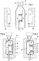
- a device for carrying out the method according to the invention can have a generally two-part blow mold 10 which is assigned a mandrel 14 which projects into the mold cavity 12 from below between the two blow mold halves 10a, 10b.
- the device also has an extrusion device with an extrusion head 16, which is provided with an annular outlet opening for the thermoplastic material when producing a tubular preform.
- This annular outlet opening is delimited on the inside by a core 18 which is provided with a channel 20 which is open at the bottom for a gaseous medium.
- the mandrel 14 can be provided with axial channels, not shown in the drawing, which, for. B. are arranged coaxially with each other, of which one channel is used to supply a pressure medium and the other channel is used to supply the reaction gas.
- axial channels not shown in the drawing, which, for. B. are arranged coaxially with each other, of which one channel is used to supply a pressure medium and the other channel is used to supply the reaction gas.
- the mandrel 14 is provided at its end projecting into the blow mold with a rod-like extension 22, which, however, has a noticeably smaller diameter than the mandrel 14.
- This extension 22 is arranged eccentrically on the mandrel 14, running parallel to it, so that a Rotation of the rotatably mounted mandrel 14 about its longitudinal axis a corresponding pivoting of the extension 22 about the longitudinal axis of the mandrel 14 results.
- the extension 22 serves during the manufacture of a product as a supporting element for a holder 24 which in turn carries an additional body 26 which is to be attached to the hollow body to be produced in the blow mold 10.
- the work cycle for producing a hollow body begins with the blow mold open (FIG. 1) with the mounting of the holder 24 on the rod-like extension 22 serving as a supporting element, which will be described in detail, the parts initially occupying the position shown in FIG. 1. That is to say that the mandrel 14 has previously been rotated into a position in which the rod-like support element 22 is located in the left vertex of the circular path, as is shown in FIGS. 1-3, which it rotates when the mandrel 14 is rotated would describe 180 °.
- a preform 28 is now extruded between the latter and is open at its lower end.
- the preform 28 is tubular. However, it can also be designed in a different way, for example consist of a band which is approximately U-shaped in cross section, or also consist of two bands which are connected to one another when the blow mold 10 is closed.
- Fig. 1 shows that the preform 28 has a diameter that allows it to be guided during the extrusion process relatively over the bracket 24 carried by the extension 22 with additional body 26.
- a gas is normally introduced into the preform through the channel 20, through which the preform 28 can undergo some pre-expansion, although the overpressure present in the preform 28 is small due to the fact that the preform is open at the bottom.
- the blow mold 10 is closed by correspondingly moving the two blow mold halves 10a, 10b from the positions according to FIG. 1 into those according to FIGS. 2 and 3.
- the preform 28 is squeezed at its upper end by the two blow mold halves 10a, 10b from the material still hanging on the extrusion head 16 and closed in the process. At the lower end, the preform is pressed around the mandrel 14, possibly with excess material squeezed off.
- inert gas is first introduced through one of the channels in the mandrel 14 under pressure into the possibly pre-expanded preform 16, with the result that the preform is brought to bear on the wall of the mold cavity 12 everywhere and thus takes on its shape, which essentially corresponds to the shape of the hollow body 30 to be produced.
- Fig. 2 of the drawing shows that due to the selected position of the mandrel 14 in the circumferential direction, the holder 24 and thus the additional body 26 carried by it in this process stage at a distance of - based on the representations of FIGS. 2 and 3 - right Are wall area 32 of the hollow body 30 to which the additional body 26 is to be attached.
- the distance between the bottom 34 of the cup-shaped additional body 26 and the wall area 32 is so large that a treatment medium located within the hollow body 30 has unimpeded access to this wall area 32 at all times.
- the distance of the additional body 26 from the other wall areas is so great that a medium flowing inside the hollow body 30 has unrestricted access everywhere.
- the Mandrel 14 rotated by 180 ° about its longitudinal axis. This results in a corresponding pivoting of the rod-like extension 22 serving as a supporting element for the holder 24 and the additional body 26, with the result that, in the course of this pivoting movement, the holder 24 with the additional body 26 moves from the position according to FIG. 2 into that according to FIG is shifted to the right.
- the eccentricity of the extension 22 with respect to the mandrel 14 is chosen such that at the end of the pivoting movement the widened foot parts 36 of the holder 24 facing the wall region 32 come into contact with the wall region 32 under a certain pressure and thus form a firm connection between the holder 24 and wall area 32 are welded.
- FIG. 3 This position of the latter which brings about the fixed connection between the wall region 32 and the holder 24 is shown in FIG. 3. Since the holder 24 with the additional body 26 should always assume positions during the pivoting movement carried out by the extension 22, which run parallel to a plane which is defined by the starting position of the holder 24 and additional body 26 shown in FIG. 2, the rod-like extension 22 about its longitudinal axis relative to the mandrel 14 rotatably mounted in the latter, means not shown being provided in the drawing, which fix the angular position of the extension 22 with respect to its longitudinal axis.
- the treatment medium is then blown into the hollow body 30 via the mandrel 14 or another feed, which leads to the already mentioned implementation of the inner surface of the wall leads.
- Fig. 3 of the drawing shows that the additional body 26 is on all sides so far from the wall of the hollow body 30 that the treatment gas to all wall areas, in particular also to the wall area 32, which is opposite the bottom 34 of the additional body 26, unimpeded access Has.
- the additional body 26 designed as a swirl pot is then moved from the position according to FIG. 3 to the position according to FIG. 5, in which the bottom 34 of the swirl pot rests in the region 32 against the wall of the hollow body. This can be done inside or outside the blow mold.
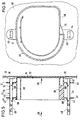
- FIGS. 4-6 show details of the design of the holder 24 and the additional body 26.
- the latter has the already mentioned bottom 34 and side walls 38 and internals located within the pot, which, however, are of no importance for the invention and depend on the respective requirements and circumstances .
- the additional body 26 is provided with two extensions 40, 41, which run approximately parallel to the bottom 34 and the wall area 32 and have openings 42.
- the extensions 40, 41 with the openings 42 serve as guide means for the additional body 26 on the holder 24, which essentially consists of two stands 44, 45, which run essentially perpendicular to the wall region 32 of the hollow body 30.
- the stands 44, 45 have, as can be seen in particular in FIG. 6, an essentially rectangular cross section.
- they are provided with foot-like widenings 36.
- the boundary surfaces of the widened, approximately plate-shaped foot parts 36 facing the wall area 32 become at the end of the above-described movement of the parts from the position according to FIG. 2 into that of FIG. 3 against the still hot one and thus pressed plastic inner boundary surface of the wall area 32 for the purpose of producing a welded connection.
- each stand 44, 45 facing away from the foot-like widening 36, an opening 48 or 49 is provided, of which the opening 48 is circular in cross-section and is likewise adapted to the extension 22 which is circular in cross-section over most of its longitudinal extent.
- the end section 50 of the rod-like extension 22, however, has a positive, here square cross-section, to which the opening 49 in the stand 45 is adapted. This square cross section of the opening 49 and the end section 50 brings about a positive connection which prevents a pivoting movement of the holder 24 consisting of the two stands 44, 45 about the longitudinal axis of the extension 22.
- the holder 24 is first connected to the additional body 26 in such a way that the two stands 44, 45 are inserted through the holes 42 in the associated appendages 40, 41, in such a way that the parts in FIGS. assume the relative position shown to each other. Thereafter, the unit consisting of the holder 24 and the additional body 26 is plugged onto the rod-like extension 22 serving as the supporting element, so that the result is the position of the parts shown in FIGS. 1 and 2.
- the stand 45 is provided at the level of the extension 41 located near the bottom 34 with small, rounded projections 51, 52 which, in the position of the parts according to FIGS. 2-4, have an extension 41 between them record and secure it against displacement relative to the stand 45 as long as no excessive force, which is directed accordingly, acts on the stand 45 and / or additional body 26.
- the stand 45 will normally be made of thermoplastic, this is the knob-like one Projections 51, 52, which are integral with the stand 45, forming material elastically deformable, so that in particular when the extension 41 is made of plastic, the stand 45 with the projections 51, 52 can be guided through the hole in the extension 41 , wherein only a somewhat greater force is to be applied in order to overcome the resistance caused by the projections 51 with corresponding deformation of the projections 51 and / or the extension 41.
- the expansion elements 60 serving as locking means for the additional body.
- the extension 22 serving as a supporting element can be made by a corresponding axial movement the two stands 44, 45 of the holder 24 are retracted in the direction of the arrow 54.
- the additional body 26 is moved in the direction of arrow 56 from the position shown in FIGS. 3 and 4 to the position according to FIG. 5, in which the bottom 34 of the additional body lies more or less closely against the wall area 32.
- a force is again to be applied which is sufficient to overcome the resistance of the projections 52 and the locking elements 60 on the stand 45.
- FIGS. 1-6 other means can also be provided to secure the additional body in its respective position on the stands 44, 45. If necessary, this can also be done via frictional forces, the cross-sectional dimensions of at least one of the two stands 44, 45 then corresponding to the dimensions of the holes 42 in the extensions 40, 41 serving as guide means would have to be adapted.
- the projections 60 can also be integrally formed on the uprights 44, 45, for example in the injection molding process. The same applies to the projections 51, 52.
- the holder 24 is in two pieces, since it consists of the two stands 44, 45, which are connected independently of each other to the additional body 26 and are located outside of the same.
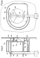
- the holder 124 is provided with a star-shaped foot part 136, on the latter a plate 162 is attached to the rod-shaped support element 122 facing side, which is supported by the two stands 144, 145. The latter are designed in the manner already described and can be plugged onto the support element 122.
- the holder 124 is provided with a star-shaped foot part 136, on the latter a plate 162 is attached to the rod-shaped support element 122 facing side, which is supported by the two stands 144, 145. The latter are designed in the manner already described and can be plugged onto the support element 122.
- the two stands 144, 145 are located within the additional body 126. Accordingly, there is a need to provide the bottom 134 of the additional body 126 designed as a surge pot with an opening 135 which corresponds to the star-shaped configuration of the foot part 136 is also advantageously star-shaped.
- the advantage of this star-shaped configuration is that the contact surfaces (cf. contact surfaces 266 in FIG.
- the projections 151, 152 on the foot part 136 also have the function of securing the additional body 126 in its first position on the holder 124 against unintentional displacement.
- the same also applies to the projections 160 which, when the holder 124 and the additional body 126 are assembled, may first be brought into a position which allows the foot part 136 to be guided through the opening 135 located in the bottom 134 of the additional body 126.
- the boundaries of the star-shaped opening 135 located in the bottom 134 form the guide means during the displacement of the additional body 126 from its first position shown in FIG. 7 of the drawing to its second position.
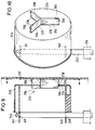
- FIGS. 9 and 10 show a third embodiment in which parts corresponding to embodiment 1-6 are provided with the same, but 200 higher reference numerals.
- the holder 224 to be connected to the wall area 232 of the hollow body is star-shaped, so that only the narrow end faces 266 of the star are connected to the wall and cover only correspondingly small sections of the wall.
- the additional body 226 and the holder 224 are produced in one piece in the position shown in FIG. 9, for example in the injection molding process.
- the transition 264 of the bottom 234 of the additional body 226 to the holder 224 penetrating the bottom is designed as a predetermined breaking point.
- the latter comes into operation if, after the treatment of the inner surface 232, the additional body is brought into its second position on or near the wall with a corresponding effort.
- the predetermined breaking point is designed and dimensioned such that a force must be exerted in order to bring about the breaking, which force is greater than the force required for proper welding of the foot part 236 to the wall 232 is required. Since in this embodiment the holder 224 is held by the additional body 226, as long as the unit consisting of the holder 224 and the additional body 226 is held by the extension 222 serving as a supporting element, the additional body 226 is provided with extensions 240, 241, on which openings 248 or 249 are attached for the passage of the rod-like support element 222.
- Figure 9 of the drawing shows the parts in positions corresponding to those of Figure 3.
- the foot part 236 of the holder 224 is pressed against the wall region 332 by a corresponding rotation of the mandrel 214, which leads to a corresponding pivoting of the support element 222 and thus to the necessary displacement of the holder 224 and additional body 226 existing unit leads.
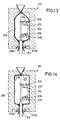
- the process sequence in the exemplary embodiment according to FIGS. 11-14 essentially corresponds to the process sequence in the exemplary embodiments described above, so that identical parts are also provided with the same, but 300 higher reference numerals than the reference symbols of the exemplary embodiment according to FIGS. 1-3 .
- the mandrel 314 which is also provided with channels (not shown in the drawing) for the supply of a pressure medium or the supply of the reaction gas, carries a rod-like extension 322 which can be arranged centrally.
- the extension 322 does not have to perform a pivoting movement about the longitudinal axis of the mandrel 314 in order to connect the holder 324 and the additional body 326 carried by it to the wall of the hollow body. Rather, the connection between the holder 324 and the wall of the hollow body is brought about by the closing movement of the blow molded part 310b.
- the extension 322 is arranged such that the holder 324 assumes a position in which the foot parts 336 come into contact with the wall of the hollow body 330 at least in the final phase of the closing movement of the Blaformteil 310b and are pressed so firmly against the wall that a sufficiently firm connection is established.
- the blow mold parts 310a, 310b are different since the blow mold 310 is not divided in half.
- a further difference compared to the device according to FIGS. 1-3 is that additionally clamping jaws 370a, 370b are provided in the lower area of the blow mold 310, of which the clamping jaw 370a is assigned to the blow molding part 310a and the clamping jaw 370b to the blow molding part 310b.
- Both clamping jaws 370a, 370b can be moved independently of the blow molded parts 310a, 310b.
- the drive means for the clamping jaws are not shown in the drawing for reasons of clarity.
- the device of the exemplary embodiment according to FIGS. 11-14 is provided with an additional transport means 316, by means of which the preform 328 is removed from the extrusion head, not shown in FIGS. 11-14, held and transported into the open blow mold 310.
- Such an additional means of transport is such.
- Such transport and holding means for the preform are state of the art. For example, they can be designed as grippers, but also in a different way. Since its design has nothing to do with the present invention, the means of transport 316 is only indicated in the drawing.
- FIG. 12 A first phase of this expansion process is shown in FIG. 12.
- the wall area 332 is pressed by the wall of the blow-molded part 310b against the foot parts 336 of the holder 324 carried by the mandrel 314 which is not moved in the process, the pressure being sufficient for the subsequent solidification of the part which forms the hollow body Material to bring about a permanent weld between the foot parts 336 of the bracket 324 and the wall portion 332 of the hollow body.
- the process stage at which the foot parts 336 are in contact with the wall area 332 is shown in FIG.
- the blow mold 310 is completely closed.
- the expansion of the preform 328 to the hollow body 330 has already been largely completed at this point in time, so that in the following process section only the two end regions of the preform located up and down to the system are to be expanded on the blow mold.
- the preform 328 already begins to expand before the blow mold 310 is completely closed, the preform is more likely to be deformed, since the preform may be expanded more than at least in some areas before the blow mold is finally closed this corresponds to the cross-sectional shape of the finished hollow body 330, so that by closing the blow molded parts the preform 328 may even experience a cross-sectional narrowing in its central region.
- the establishment of the connection between the holder 324 and the wall of the hollow body 330 presupposes that the wall region 332, that is to say the wall region on which the connection to the holder 324 is made, on the wall of the blow mold 310, that is to say, more precisely abuts the wall of the blow molded part 310b, the closing movement of which exerts the pressure for establishing the connection between the holder and the hollow body wall.
- the additional body 326 is moved into the position according to FIG. 5 in the manner already described in connection with the other exemplary embodiments.
- the additional material required for the mounting is negligible.
- the fact that the holder remains in addition to the additional body in the hollow body after its completion is not a disadvantage.
- the surface treatment can also be carried out by sulfonation.
Landscapes
- Engineering & Computer Science (AREA)
- Mechanical Engineering (AREA)
- Manufacturing & Machinery (AREA)
- Life Sciences & Earth Sciences (AREA)
- Sustainable Development (AREA)
- Sustainable Energy (AREA)
- Chemical & Material Sciences (AREA)
- Combustion & Propulsion (AREA)
- Transportation (AREA)
- Blow-Moulding Or Thermoforming Of Plastics Or The Like (AREA)
- Moulds For Moulding Plastics Or The Like (AREA)
- Processing And Handling Of Plastics And Other Materials For Molding In General (AREA)
Description
Die Erfindung betrifft ein Verfahren zum Herstellen von Hohlkörpern aus thermoplastischem Kunststoff durch Blasformen gemäß dem Oberbegriff des Anspruches 1 sowie einen mittels Blasformen hergestellten Hohlkörper gemäß dem Oberbegriff des Anspruches 28.The invention relates to a method for producing hollow bodies from thermoplastic by blow molding according to the preamble of claim 1 and a hollow body produced by means of blow molding according to the preamble of
Das Anbringen von Zusatzkörpern im Inneren von im Blasverfahren hergestellten Hohlkörpern ist bekannt. In der Mehrzahl der Fälle wird dazu beim Extrudieren des Vorformlings letzterer über den von einem Tragelement gehaltenen Zusatzkörper geführt, worauf dann beim Schließen der im allgemeinen zweiteiligen Blasform um den Vorformling der Zusatzkörper innerhalb des zu diesem Zeitpunkt im allgemeinen bereits voraufgeweiteten Vorformlings eingeschlossen wird. Überwiegend sind derartige Vorformlinge schlauchförmig ausgebildet, so daß im folgenden ausschließlich von schlauchförmigen Vorformlingen gesprochen wird, ohne daß dadurch die Anwendung der Lehre gemaß der Erfindung auf in anderer Weise ausgebildete Vorformlinge ausgeschlossen sein soll. Nach dem Aufweiten des Vorformlings in die Gestalt des herzustellenden Hohlkörpers wird der Zusatzkörper mit der inneren Begrenzungsfläche der Wandung desselben verbunden. Dies geschieht im allgemeinen in der Weise, daß der Zusatzkörper mit der Wandung des Hohlkörpers verschweißt wird, wobei der Zusatzkörper zumindest teilweise aus Material besteht, welches mit dem den Hohlkörper bildenden Material verschweißbar ist. Die Herstellung einer solchen Schweißverbindung ist z. B. dann möglich, wenn Hohlkörper und Zusatzkörper an den Verbindungsstellen aus Polyolefinen, beispielsweise Polyethylen, bestehen. Dabei ist es erforderlich, daß im Augenblick des Herstellens der Verbindung zwischen Zusatzkörper und Hohlkörperwandung letztere noch heiß und plastisch, also in einem Zustand ist, der das Entstehen einer Schweißverbindung zuläßt (DE-A-32 23 081).The attachment of additional bodies in the interior of hollow bodies produced by the blowing process is known. In the majority of cases, when the preform is extruded, the latter is guided over the additional body held by a supporting element, whereupon when the generally two-part blow mold is closed around the preform, the additional body is enclosed within the preform, which is generally already pre-expanded at this time. Preforms of this type are predominantly tubular, so that only tubular preforms are referred to below, without the application of the teaching according to the invention to preforms formed in any other way being thereby excluded. After the preform has expanded into the shape of the hollow body to be produced, the additional body is connected to the inner boundary surface of the wall thereof. This is generally done in such a way that the additional body is welded to the wall of the hollow body, the additional body at least partially consisting of material which is made with the material forming the hollow body is weldable. The production of such a welded joint is e.g. B. possible if the hollow body and additional body at the connection points made of polyolefins, for example polyethylene. It is necessary that the connection between the additional body and the hollow body wall is still hot and plastic, that is to say in a state which permits the formation of a welded connection (DE-A-32 23 081).
Typische Anwendungsfälle derartiger mit einem innen angebrachten Zusatzkörper versehene Hohlkörper sind Kfz-Tanks, die, soweit sie aus Kunststoff bestehen, überwiegend im Extrusions-Blasverfahren hergestellt werden. Bei dem Zusatzkörper kann es sich um einen Schwalltopf handeln, der bei im Kraftwagen montiertem Tank in dessen unterem Bereich angeordnet ist und insbesondere dafür sorgt, daß unabhängig von den auf den im Tank befindlichen Kraftstoff einwirkenden Kräften, z. B. Fliehkräften bei Kurvenfahrten, im Bereich der Ansaugöffnung für die Kraftstoffpumpe immer ausreichend Kraftstoff verfügbar ist. D. h., daß die Ansaugöffnung für die Zuleitung zur Pumpe im allgemeinen sich im Schwalltopf befindet, der im wesentlichen aus einem Boden und von diesem ausgehenden, im allgemeinen senkrecht zum Boden verlaufenden Wandbereichen besteht, die jedoch mit Durchgängen für den Kraftstoff versehen sind. An seiner dem Boden abgekehrten Seite ist der Schwalltopf im allgemeinen offen. Derartige Schwalltöpfe sind bekannt.Typical applications of such hollow bodies provided with an internally attached additional body are motor vehicle tanks which, insofar as they are made of plastic, are predominantly produced by extrusion blow molding. The additional body may be a swirl pot, which is arranged in the lower region of the tank when it is mounted in the motor vehicle and, in particular, ensures that irrespective of the forces acting on the fuel in the tank, e.g. B. centrifugal forces when cornering, sufficient fuel is always available in the area of the intake opening for the fuel pump. In other words, the suction opening for the supply line to the pump is generally located in the baffle, which essentially consists of a floor and wall areas extending from it, which generally run perpendicular to the floor, but which are provided with passages for the fuel. The swirl pot is generally open on its side facing away from the floor. Such surge pots are known.
Da die Wandungen von Kraftstofftanks, die aus einem Polyolefin, insbesondere Polyethylen bestehen, jedenfalls für solche Kohlenwasserstoffe, die in flüssigen Kraftstoffen enthalten sind, permeabel sind, ist es üblich, die Wandung von Kraftstoffbehältern vor deren Verwendung einem reaktiven Gas auszusetzen. Im allgemeinen handelt es sich dabei um ein Fluor enthaltendes Gasgemisch, welches in den Hohlkörper eingeblasen wird und zu einer Umsetzung der inneren Oberflächenschicht der Wandung aus Polyethylen oder dergleichen führt mit dem Ergebnis, daß diese Oberflächenschicht und damit die Wandung insgesamt für Kohlenwasserstoffe nahezu undurchlässig, jedenfalls so wenig durchlässig wird, daß die noch hindurchtretenden Kohlenwasserstoffe quantitativ nicht ins Gewicht fallen (EP-A-0 176 044).Since the walls of fuel tanks, which consist of a polyolefin, in particular polyethylene, are in any case permeable to hydrocarbons contained in liquid fuels, it is customary to expose the walls of fuel tanks to a reactive gas before they are used. In general, this is a fluorine-containing gas mixture which is blown into the hollow body and leads to a conversion of the inner surface layer of the wall from polyethylene or the like, with the result that that this surface layer and thus the wall as a whole becomes almost impermeable to hydrocarbons, in any case so little permeable that the hydrocarbons which still pass through are of no quantitative importance (EP-A-0 176 044).
Bei bekannten Verfahren der einleitend beschriebenen Art wird im allgemeinen so vorgegangen, daß nach dem Aufweiten zunächst der Zusatzkörper mit der Wandung des Hohlkörpers verbunden wird, worauf dann das Fluorieren oder eine andere die Permeabilität für Kohlenwasserstoffe herabsetzende Behandlung durchgeführt wird. Dies hat zur Folge, daß der Bereich der inneren Oberfläche der Wandung, an welchem der Zusatzkörper angebracht ist, durch letzteren gegenüber dem Reaktionsmedium abgeschirmt wird mit dem Ergebnis, daß in diesem während der Behandlung mit dem Reaktionsmedium abgeschirmten Bereich keine oder nur eine geringe Umsetzung der Oberflächenschicht der Wandung des Hohlkörpers erfolgt. Dieser nachteilige Effekt könnte möglicherweise in einigen Teilbereichen, also dort, wo der Zusatzkörper nicht an der Wandung anliegt, durch eine längere Einwirkungszeit des Reaktionsmediums vermieden werden. Dies würde jedoch zu einer längeren Behandlungsdauer mit entsprechend geringerer Produktivität führen.In known methods of the type described in the introduction, the procedure is generally such that, after the expansion, the additional body is first connected to the wall of the hollow body, whereupon the fluorination or another treatment which reduces the permeability to hydrocarbons is carried out. This has the consequence that the area of the inner surface of the wall to which the additional body is attached is shielded by the latter from the reaction medium with the result that in this area shielded during the treatment with the reaction medium there is little or no conversion of the Surface layer of the wall of the hollow body takes place. This disadvantageous effect could possibly be avoided in some areas, ie where the additional body does not lie against the wall, by a longer exposure time of the reaction medium. However, this would lead to a longer treatment period with correspondingly lower productivity.
Die bekannten Verfahren weisen insbesondere bei Verwendung der üblichen Schwalltöpfe in Kfz-Tanks Nachteile auf, da erstere im allgemeinen mit einem großflächigen Boden versehen sind, der direkt an der inneren Oberfläche der Hohlkörperwandung anliegt und somit einen entsprechend großen Bereich derselben abdeckt und durch das Reaktionsmedium unbehandelt läßt. Dieser unbehandelt bleibende Bereich der Hohlkörperwandung führt zwar nicht zwangsläufig zu einer Durchlässigkeit für Kohlenwasserstoffe, die die Verwendung des Kohlkörpers als Tank ausschließen würde, zumal durch das Vorhandensein des Bodens des Schwalltopfes in diesem Bereich die dort insgesamt vorhandene Wandung - Wandung des Hohlkörpers plus Boden des Schwalltopfes - dicker ist als in den übrigen Bereichen des Tanks. Jedoch führt die in diesem Bereich fehlende Oberflächenbehandlung dazu, daß im Laufe der Zeit bei der Benutzung des Tanks Kohlenwasserstoffe aus dem Kraftstoff in diesen Bereich der Wandung des Tanks eindringen. Dies hat unter anderem zur Folge, daß die von den Kohlenwasserstoffen durchsetzten Bereiche der Wandung z. B. durch Quellen eine gewisse Deformation erfahren. Das Ausmaß dieser Deformation braucht nicht sehr groß zu sein. Es bewirkt jedoch in jedem Fall z. B. das Auftreten von Spannungen in der Wandung, die unerwünscht sind und zudem zu Verformungen von Wandungsbereichen führen können, die sich bis auf den Zusatzkörper unter Veränderung der Position desselben im Tank auswirken können, so daß im Zusatzkörper befindliche Bauteile unter Umständen in einer ihre Funktion beeinträchtigenden Weise beeinflußt werden. Selbstverständlich werden die Kohlenwasserstoffe auch in die Boden- und Wandungsbereiche eines z.B. aus Polyethylen bestehenden Schwalltopfes eindringen und dort ebenfalls ein Quellen dieser Teile bewirken. Dies ist jedoch beim Schwalltopf ohne Bedeutung, da er keine großen mechanischen Beanspruchungen erfährt und außerdem innerhalb des Tankes angeordnet ist. Zwar wirkt das Reaktionsmedium, mit dem die innere Oberfläche des Tankes behandelt wird, auch auf den Schwalltopf - oder irgendeinen anderen innerhalb des Hohlkörpers befindlichen Zusatzkörper - ein, ohne allerdings dabei die Wirkungen auf den Oberflächen des Zusatzkörpers zu erzielen, die an der inneren Oberfläche des Hohlkörpers eintreten. Dies ist im wesentlichen darauf zurückzuführen, daß der Zusatzkörper eine wesentlich niedrigere Temperatur aufweist als die noch plastische und somit heiße Wandung des Hohlkörpers. Die Temperatur der auf die beschriebene Weise zu behandelnden Oberflächen stellt eine wesentliche Voraussetzung für das Eintreten des angestrebten Effektes dar.The known methods have disadvantages in particular when using the usual baffles in motor vehicle tanks, since the former are generally provided with a large-area floor which lies directly against the inner surface of the hollow body wall and thus covers a correspondingly large area thereof and is untreated by the reaction medium leaves. This area of the hollow body wall which remains untreated does not necessarily lead to a permeability to hydrocarbons, which would preclude the use of the carbon body as a tank, especially since the total wall present there - wall of the hollow body plus floor of the baffle pot due to the presence of the bottom of the baffle - is thicker than in the other areas of the tank. However As a result of the lack of surface treatment in this area, hydrocarbons from the fuel penetrate into this area of the wall of the tank over time when the tank is used. Among other things, this has the consequence that the areas of the wall penetrated by the hydrocarbons, for. B. experience a certain deformation by swelling. The extent of this deformation need not be very large. However, it causes z. B. the occurrence of stresses in the wall, which are undesirable and can also lead to deformation of wall areas, which can affect the additional body while changing the position of the same in the tank, so that components located in the additional body may be in a function impairing manner. Of course, the hydrocarbons will also penetrate into the bottom and wall areas of a baffle made, for example, of polyethylene and likewise cause these parts to swell there. However, this is irrelevant for the surge pot, since it is not subjected to great mechanical stresses and is also arranged inside the tank. The reaction medium with which the inner surface of the tank is treated also acts on the baffle - or any other additional body located within the hollow body - without, however, achieving the effects on the surfaces of the additional body that are on the inner surface of the Enter the hollow body. This is essentially due to the fact that the additional body has a significantly lower temperature than the still plastic and thus hot wall of the hollow body. The temperature of the surfaces to be treated in the manner described is an essential prerequisite for the desired effect to occur.
Der Erfindung liegt die Aufgabe zugrunde, Verfahren und Hohlkörper der einleitend beschriebenen Art so abzuwandeln bzw. auszugestalten, daß die vorbeschriebenen Nachteile vermieden werden. Es soll einerseits wie beim Stand der Technik möglich sein, Zusatzkörper innen an im Blasverfahren hergestellten Hohlkörpern, also beispielsweise Schwalltöpfe an Kraftstofftanks, anzubringen, ohne daß dabei bezüglich Materialauswahl, Positionierung usw. irgendwelche Besonderheiten zu beachten wären. Das Verfahren soll auf üblichen und vorhandenen Maschinen ausführbar sein. Der fertige Hohlkörper soll bezüglich des Einbaus, seiner Verwendbarkeit usw. keinen Einschränkungen unterliegen, die bei bekannten derartigen Hohlkörpern nicht zu beachten wären. Insbesondere soll die Produktivität des Verfahrens nicht abnehmen. Ein ggf. in Betracht kommender Mehraufwand soll so gering sein, daß er im Vergleich zu dem angestrebten und erzielten Effekt kaum ins Gewicht fällt.The object of the invention is to modify or design methods and hollow bodies of the type described in the introduction in such a way that the disadvantages described above are avoided. On the one hand, it should be possible as in the prior art be to attach additional bodies on the inside of hollow bodies produced by the blowing process, for example baffles on fuel tanks, without any special features having to be considered with regard to material selection, positioning, etc. The process should be executable on conventional and existing machines. The finished hollow body should not be subject to any restrictions with regard to the installation, its usability, etc., which would not have to be observed in known hollow bodies of this type. In particular, the productivity of the process should not decrease. Any additional effort that may be considered should be so small that it hardly matters in comparison to the desired and achieved effect.
Diese Aufgabe wird mit den im Kennzeichen des Anspruches 1 bzw. des Anspruches 28 angegebenen Merkmalen gelöst.This object is achieved with the features specified in the characterizing part of claim 1 and claim 28.
Das Verfahren gemäß der Erfindung läßt sich dahingehend zusammenfassen, daß vor der Behandlung des Hohlkörpers mit dem Reaktionsmedium lediglich eine Halterung an der Innenwandung angebracht wird, die den Zusatzkörper trägt, der jedoch zunächst in einem Abstand von dem Wandbereich des Hohlkörpers, mit dem er zu verbinden ist, gehalten wird, so daß das Behandlungsgas auch in den Bereich zwischen Zusatzkörper und Wandung eintreten kann, der später vom Zusatzkörper ganz oder teilweise abgedeckt oder doch zumindest abgeschirmt ist. Erst nach ausreichender Behandlung mit dem Reaktionsmedium wird der Zusatzkörper relativ zur Halterung in seine Endposition verschoben und in dieser in geeigneter Weise fixiert. Zwar sind auch beim Verfahren gemäß der Erfindung am fertigen Hohlkörper Wandbereiche vorhanden, die innenseitig durch die mit diesen Bereichen verbundenen Teile der Halterung während der Behandlung mit dem Reaktionsmedium abgedeckt sind, so daß dort keine oder nur geringere Umsetzungen mit dem Reaktionsmedium stattfinden. Diese Bereiche haben jedoch eine geringe Flächenausdehnung, so daß die durch das Eindringen von Kohlenwasserstoffen in diesen Bereichen bewirkten Quellungen des Materials ohne merklichen Einfluß auf die Qualität des fertigen Hohlkörpers, also beispielsweise eines Kraftfahrzeugtanks, bleiben.The method according to the invention can be summarized in that, before the treatment of the hollow body with the reaction medium, only a holder is attached to the inner wall which carries the additional body, but which is initially at a distance from the wall region of the hollow body with which it is to be connected is held so that the treatment gas can also enter the area between the additional body and the wall, which is later completely or partially covered or at least shielded by the additional body. Only after sufficient treatment with the reaction medium is the additional body moved relative to the holder into its end position and fixed in a suitable manner. In the method according to the invention, wall areas are also present on the finished hollow body, which are covered on the inside by the parts of the holder connected to these areas during the treatment with the reaction medium, so that there are no or only minor reactions with the reaction medium. However, these areas have a small surface area, so that the swelling of the material caused by the penetration of hydrocarbons in these areas has no noticeable effect Influence on the quality of the finished hollow body, for example a motor vehicle tank, remain.
Bei Anwendung des Verfahrens gemäß der Erfindung wird eine feste direkte Verbindung zwischen Zusatzkörper und Wandung des Hohlköpers selbst dann nicht eintreten, wenn das Verschieben aus der ersten in die Endposition zu einem Zeitpunkt erfolgt, in welchem die Wandung des Hohlkörpers noch warmplastisch ist, da durch die zuvor erfolgte Behandlung mit dem Reaktionsgas eine Schweißverbindung und im allgemeinen auch eine Adhäsionsverbindung zwischen Hohlkörperwandung und Zusatzkörper jedenfalls nicht mit der erforderlichen Festigkeit hergestellt werden können. Dies ist jedoch nicht erforderlich, da die Halterung ohne weiteres so ausgebildet und an der Hohlkörperwandung angebracht werden kann, daß eine feste Verbindung zwischen dieser und der Wandung entsteht, so daß es nur noch darauf ankommt, den Zusatzkörper in seiner Endposition in ausreichend zuverlässiger Weise an der Halterung zu fixieren.When using the method according to the invention, a firm direct connection between the additional body and the wall of the hollow body will not occur even if the shift from the first to the end position occurs at a time when the wall of the hollow body is still hot plastic, because of the previously carried out with the reaction gas, a welded joint and in general also an adhesive bond between the hollow body wall and the additional body cannot be produced with the required strength. However, this is not necessary, since the holder can easily be designed and attached to the hollow body wall in such a way that a firm connection is created between it and the wall, so that the only thing that matters is that the additional body is in its end position in a sufficiently reliable manner to fix the bracket.
Ein weiterer wesentlicher Vorteil der Erfindung besteht darin, daß die Wahl des Materials für den Zusatzkörper keinerlei Beschränkungen unterliegt, da der Zusatzkörper nicht mehr direkt mittels Schweißen, Heißkleben oder dergleichen an der Wandung des Hohlkörpers befestigt wird, sondern von der Halterung getragen wird und mit dieser nur in geeigneter Weise mechanisch verbunden zu werden braucht. Es ist also beispielsweise ohne weiteres möglich, einen Kraftstofftank aus Kunststoff mit einem Schwalltopf aus Stahlblech zu versehen.Another important advantage of the invention is that the choice of material for the additional body is not subject to any restrictions, since the additional body is no longer attached directly to the wall of the hollow body by means of welding, hot gluing or the like, but is carried by the holder and with it only needs to be mechanically connected in a suitable manner. It is therefore easily possible, for example, to provide a plastic fuel tank with a steel swirl pot.
Weiterhin besteht bei Anwendung des Verfahrens gemäß der Erfindung keine Notwendigkeit, den Zusatzkörper in seiner Endposition in direkter Anlage an der Wandung des Hohlkörpers zu positionieren. Vielmehr ist auch eine Endposition möglich, in der sich der Zusatzkörper in einem geringen Abstand von der Wandung befindet, wenngleich die erstgenannte Möglichkeit häufig die zweckmäßigere sein wird.Furthermore, when using the method according to the invention, there is no need to position the additional body in its end position in direct contact with the wall of the hollow body. Rather, an end position is also possible in which the additional body is located at a short distance from the wall, although the former option will often be the more appropriate.
Die Verschiebung des Zusatzkörpers aus seiner ersten Position in die zweite Position kann erfolgen, solange sich der Hohlkörper in der noch geschlossenen Blasform befindet. Es ist aber auch möglich, diese Verschiebung zu einem Zeitpunkt durchzuführen, zu welchem der Hohlkörper bereits aus der Blasform herausgenommen worden ist und z.B. Komplettierungsarbeiten an ihm durchgeführt werden. Dabei ist es in vielen Fällen, insbesondere bei Kraftstofftanks, erforderlich, den Hohlkörper mit einer zusätzlichen Öffnung zu versehen. Es bietet sich an, die Verschiebung des Zusatzkörpers dann durchzuführen, nachdem diese zusätzliche Öffnung angebracht worden ist, die zudem bei Kraftstofftanks häufig etwa gegenüber dem Schwalltopf anzubringen ist oder angebracht werden kann.The displacement of the additional body from its first position into the second position can take place as long as the hollow body is in the still closed blow mold. However, it is also possible to carry out this displacement at a point in time at which the hollow body has already been removed from the blow mold and e.g. Completion work to be performed on it. In many cases, particularly in the case of fuel tanks, it is necessary to provide the hollow body with an additional opening. It makes sense to carry out the displacement of the additional body after this additional opening has been made, which, moreover, is often to be or can be attached to fuel tanks in relation to the swirl pot.
Weitere mögliche Ausgestaltungen der Erfindung sind in den Unteransprüchen angeführt.Further possible embodiments of the invention are set out in the subclaims.
In den Zeichnungen sind einige derzeit bevorzugte Ausführungsbeispiele der Erfindung im Schema dargestellt. Es zeigen
- Fig. 1 - 3
- jeweils in Seitenansicht, teilweise im Schnitt, eine Vorrichtung zum Herstellen von Hohlkörpern in drei aufeinanderfolgenden Verfahrensstadien,
- Fig. 4
- einen Ausschnitt aus Fig. 3 in größerem Maßstab,
- Fig. 5
- eine der Fig. 4 entsprechende Ansicht, jedoch mit dem Zusatzkörper in der Endposition,
- Fig. 6
- die dazugehörige Draufsicht,
- Fig. 7
- eine der Fig. 4 entsprechende Darstellung einer zweiten Ausführungsform,
- Fig. 8
- die dazugehörige Draufsicht,
- Fig. 9
- eine der Fig. 4 entsprechende Ansicht einer dritten Ausführungsform,
- Fig. 10
- eine dazugehörige perspektivische Ansicht des Zusatzkörpers,
- Fig. 11-14
- jeweils in Seitenansicht, teilweise im Schnitt, eine den Fig. 1 - 3 entsprechende Darstellung einer weiteren Vorrichtung zum Herstellen von Hohlkörpern in vier aufeinanderfolgenden Verfahrensstadien.
- 1 - 3
- each in side view, partially in section, a device for producing hollow bodies in three successive process stages,
- Fig. 4
- 3 a section of FIG. 3 on a larger scale,
- Fig. 5
- 4, but with the additional body in the end position,
- Fig. 6
- the associated top view,
- Fig. 7
- 4 shows a representation of a second embodiment,
- Fig. 8
- the associated top view,
- Fig. 9
- 4 corresponding view of a third embodiment,
- Fig. 10
- an associated perspective view of the additional body,
- Fig. 11-14
- each in side view, partly in section, a representation corresponding to FIGS. 1-3 of a further device for producing hollow bodies in four successive process stages.
Eine Vorrichtung zur Durchführung des Verfahrens nach der Erfindung kann gemäß den Darstellungen der Fig. 1 - 3 eine im allgemeinen zweigeteilte Blasform 10 aufweisen, der ein zwischen die beiden Blasformhälften 10a, 10b von unten in das Formnest 12 hineinragender Dorn 14 zugeordnet ist.1-3, a device for carrying out the method according to the invention can have a generally two-
Die Vorrichtung weist weiterhin eine Extrusionsvorrichtung mit einem Extrusionskopf 16 auf, der bei Herstellung eines schlauchförmigen Vorformlings mit einer ringförmigen Austrittsöffnung für das thermoplastische Material versehen ist. Diese ringförmige Austrittsöffnung ist innenseitig durch einen Kern 18 begrenzt, der mit einem nach unten offenen Kanal 20 für ein gasförmiges Medium versehen ist.The device also has an extrusion device with an
Der Dorn 14 kann mit in der Zeichnung nicht dargestellten axialen Kanälen versehen sein, die z. B. zueinander koaxial angeordnet sind, von denen der eine Kanal der Zuführung eines Druckmediums und der andere Kanal der Zuführung des Reaktionsgases dient. Dazu wird z.B. auf die EP-OS 0 176 044 und auf die entsprechende US-PS 4,617,077 verwiesen, die Einzelheiten des Blasverfahrens und auch von Möglichkeiten bezüglich der mit Zuführung von Aufweitmedium und Reaktionsgas zusammenhängenden Dinge beschreiben und zeigen.The
Der Dorn 14 ist an seinem in die Blasform hineinragenden Ende mit einem stangenartigen Fortsatz 22 versehen, der jedoch einen merklich kleineren Durchmesser aufweist als der Dorn 14. Dieser Fortsatz 22 ist auf dem Dorn 14, parallel zu diesem verlaufend, exzentrisch angeordnet, so daß eine Rotation des drehbar gelagerten Dornes 14 um seine Längsachse eine entsprechende Verschwenkung des Fortsatzes 22 um die Längsachse des Dornes 14 zur Folge hat. Der Fortsatz 22 dient während der Herstellung eines Erzeugnisses als Tragelement für eine Halterung 24, die ihrerseits einen Zusatzkörper 26 trägt, der an dem in der Blasform 10 herzustellenden Hohlkörper anzubringen ist.The
Der Arbeitszyklus zur Herstellung eines Hohlkörpers beginnt bei geöffneter Blasform (Fig. 1) mit dem im einzelnen noch zu beschreibenden Aufstecken der Halterung 24 auf dem als Tragelement dienenden stangenartigen Fortsatz 22, wobei die Teile zunächst die in Figur 1 dargestellte Position einnehmen. D. h., daß der Dorn 14 zuvor in eine Position gedreht worden ist, in welcher sich das stangenartige Tragelement 22 im - auf die Fig. 1 - 3 bezogen - linken Scheitelpunkt der Kreisbahn befindet, die er bei einer Drehung des Dornes 14 um 180° beschreiben würde. In diesem Stadium des Verfahrens, d.h. bei auseinanderbewegten Blasformhälften 10a, 10b wird zwischen letztere nunmehr ein Vorformling 28 aus dem Extrusionskopf 16 extrudiert, der an seinem unteren Ende offen ist. Der Vorformling 28 ist schlauchförmig ausgebildet. Er kann aber auch in anderer Weise ausgebildet sein, beispielsweise aus einem im Querschnitt etwa U-förmig gebogenen Band oder auch aus zwei Bändern bestehen, die beim Schließen der Blasform 10 miteinander verbunden werden.The work cycle for producing a hollow body begins with the blow mold open (FIG. 1) with the mounting of the
Fig. 1 läßt erkennen, daß der Vorformling 28 einen Durchmesser aufweist, der es erlaubt, ihn während des Extrusionsvorganges relativ über die vom Fortsatz 22 getragene Halterung 24 mit Zusatzkörper 26 zu führen. Während des Extrudierens des Vorformlings 28 wird normalerweise ein Gas durch den Kanal 20 in den Vorformling eingeführt, durch welches dieser eine gewisse Voraufweitung erfahren kann, wenngleich der im Vorformling 28 dabei vorhandene Überdruck aufgrund der Tatsache, daß der Vorformling unten offen ist, gering ist. Sobald der Vorformling 28 seine für die Herstellung eines Hohlkörpers erforderliche Länge erreicht hat, die etwa der in Fig. 1 dargestellten Länge entspricht, wird die Blasform 10 durch entsprechendes Verschieben der beiden Blasformhälften 10a, 10b aus den Positionen gemäß Fig. 1 in die gemäß den Figuren 2 und 3 geschlossen. Dabei wird der Vorformling 28 an seinem oberen Ende durch die beiden Blasformhälften 10a, 10b von dem noch am Extrusionskopf 16 hängenden Material abgequetscht und dabei verschlossen. Am unteren Ende wird der Vorformling um den Dorn 14, ggf. unter Abquetschen von Überschußmaterial, gepreßt. Dabei handelt es sich um Dinge, die jedem Fachmann auf dem Gebiet des Extrusions-Blasformens geläufig sind, so daß sie hier nicht gesondert erläutert zu werden brauchen.Fig. 1 shows that the
Kurz vor oder nach Beendigung des Schließens der Blasform 10 wird mit dem eigentlichen Blasvorgang begonnen. Dazu wird zunächst Inertgas über einen der im Dorn 14 befindlichen Kanäle unter Druck in den ggf. bereits voraufgeweiteten Vorformling 16 eingeführt mit dem Ergebnis, daß der Vorformling überall zur Anlage an der Wandung des Formnestes 12 gebracht wird und somit dessen Gestalt annimmt, die im wesentlichen der Gestalt des herzustellenden Hohlkörpers 30 entspricht. Fig. 2 der Zeichnung läßt erkennen, daß aufgrund der gewählten Position des Dornes 14 in Umfangsrichtung die Halterung 24 und damit der von dieser getragene Zusatzkörper 26 sich in diesem Verfahrensstadium in einem Abstand von - bezogen auf die Darstellungen der Fig. 2 und 3 - rechten Wandbereich 32 des Hohlkörpers 30 befinden, an welchem der Zusatzkörper 26 angebracht werden soll. Der Abstand zwischen dem Boden 34 des topfförmigen Zusatzkörpers 26 und dem Wandbereich 32 ist dabei so groß, daß ein innerhalb des Hohlkörpers 30 befindliches Behandlungsmedium jederzeit ungehindert Zutritt auch zu diesem Wandbereich 32 hat. Von den übrigen Wandbereichen ist der Abstand des Zusatzkörpers 26 ohnehin so groß, daß ein innerhalb des Hohlkörpers 30 strömendes Medium überall ungehindert Zutritt hat.Shortly before or after the closing of the
Möglichst sofort nach Beendigung des Aufweitvorganges wird der Dorn 14 um seine Längsachse um 180° gedreht. Dies hat eine entsprechende Verschwenkung des als Tragelement für Halterung 24 und Zusatzkörper 26 dienenden stangenartigen Fortsatzes 22 zur Folge mit dem Ergebnis, daß im Zuge dieser Schwenkbewegung Halterung 24 mit Zusatzkörper 26 aus der Position gemäß Fig. 2 in die gemäß Fig. 3, also nach rechts verschoben wird. Die Exzentrizität des Fortsatzes 22 gegenüber dem Dorn 14 ist dabei so gewählt, daß am Ende der Schwenkbewegung die dem Wandbereich 32 zugekehrten verbreiterten Fußteile 36 der Halterung 24 mit dem Wandbereich 32 unter einem gewissen Druck in Berührung kommen und damit unter Bildung einer festen Verbindung zwischen Halterung 24 und Wandbereich 32 verschweißt werden. Diese die feste Verbindung zwischen Wandbereich 32 und Halterung 24 bewirkende Position der letzteren ist in Fig. 3 dargestellt. Da die Halterung 24 mit dem Zusatzkörper 26 bei der vom Fortsatz 22 durchgeführten Schwenkbewegung immer Positionen einnehmen soll, die parallel zu einer Ebene verlaufen, die durch die in Fig. 2 dargestellte Ausgangsposition von Halterung 24 und Zusatzkörper 26 definiert ist, ist der stangenartige Fortsatz 22 um seine Längsachse relativ zum Dorn 14 drehbar in letzterem gelagert, wobei in der Zeichnung nicht dargestellte Mittel vorgesehen sind, die die Winkelstellung des Fortsatzes 22, bezogen auf seine Längsachse, fixieren. D. h., daß die Winkelposition des Fortsatzes 22 und damit der Halterung 24 sowie des von ihr getragenen Zusatzkörpers während der Schwenkbewegung des Fortsatzes 22 unverändert bleiben, welche Tatsache zu der bereits erwähnten Verschiebung führt, bei welcher Halterung und Zusatzkörper immer eine Position einnehmen, die parallel zu ihrer Ausgangsposition verläuft.Immediately after the expansion process has ended, the
Nach Herstellung der Verbindung zwischen Halterung 24 und der Wandung des Hohlkörpers 30 im Bereich 32 derselben wird dann über den Dorn 14 - oder eine andere Zuführung - das Behandlungsmedium in den Hohlkörper 30 eingeblasen, welches zu der bereits erwähnten Umsetzung der inneren Oberfläche der Wandung führt. Fig. 3 der Zeichnung läßt erkennen, daß der Zusatzkörper 26 auf allen Seiten so weit von der Wandung des Hohlkörpers 30 entfernt ist, daß das Behandlungsgas zu sämtlichen Wandbereichen, insbesondere auch zum Wandbereich 32, der dem Boden 34 des Zusatzkörpers 26 gegenüberliegt, ungehindert Zutritt hat. Nach Beendigung der Behandlung wird dann der als Schwalltopf ausgebildete Zusatzkörper 26 aus der Position gemäß Fig. 3 in die Position gemäß Fig. 5 verschoben, in welcher der Boden 34 des Schwalltopfes im Bereich 32 an der Wandung des Hohlkörpers anliegt. Dies kann innerhalb oder außerhalb der Blasform erfolgen.After establishing the connection between the
Die Figuren 4 - 6 zeigen Einzelheiten der Ausgestaltung von Halterung 24 und Zusatzkörper 26. Letzterer weist den bereits erwähnten Boden 34 sowie Seitenwände 38 und innerhalb des Topfes befindliche Einbauten auf, die jedoch für die Erfindung ohne Bedeutung sind und von den jeweiligen Erfordernissen und Gegebenheiten abhängen.FIGS. 4-6 show details of the design of the
An zwei etwa einander gegenüberliegenden Seiten ist der Zusatzkörper 26 mit jeweils zwei Fortsätzen 40, 41 versehen, die etwa parallel zum Boden 34 und zum Wandungsbereich 32 verlaufen und Öffnungen 42 aufweisen.On two approximately opposite sides, the
Die Fortsätze 40, 41 mit den Öffnungen 42 dienen als Führungsmittel für den Zusatzkörper 26 an der Halterung 24, die im wesentlichen aus zwei Ständern 44, 45 besteht, die im wesentlichen senkrecht zum Wandbereich 32 des Hohlkörpers 30 verlaufen. Die Ständer 44, 45 weisen, wie dies insbesondere die Fig. 6 erkennen läßt, einen im wesentlichen rechteckigen Querschnitt auf. An ihrem dem Wandbereich 32 des Hohlkörpers zugekehrten Ende sind sie mit fußartigen Verbreiterungen 36 versehen. Die dem Wandbereich 32 zugekehrten Begrenzungsflächen der verbreiterten, etwa plattenförmigen Fußteile 36 werden am Ende der vorstehend beschriebenen Bewegung der Teile aus der Position gemäß Fig. 2 in die der Fig. 3 gegen die noch heiße und somit plastische innere Begrenzungsfläche des Wandbereiches 32 zwecks Herstellung einer Schweißverbindung gedrückt.The
In dem der fußartigen Verbreiterung 36 abgekehrten Endbereich jedes Ständers 44, 45 ist eine Durchbrechung 48 bzw. 49 vorgesehen, von denen die Durchbrechung 48 im Querschnitt kreisrund und dem ebenfalls über den größten Teil seiner Längserstreckung im Querschnitt kreisrunden Fortsatzes 22 angepaßt ist. Der Endabschnitt 50 des stangenartigen Fortsatzes 22 hingegen weist einen formschlüssigen, hier quadratischen Querschnitt auf, an den die Durchbrechung 49 im Ständer 45 angepaßt ist. Dieser quadratische Querschnitt von Durchbrechung 49 und Endabschnitt 50 bewirkt einen Formschluß, der eine Schwenkbewegung der aus den beiden Ständern 44, 45 bestehenden Halterung 24 um die Längsache des Fortsatzes 22 verhindert.In the end region of each stand 44, 45 facing away from the foot-like widening 36, an
Die Halterung 24 wird mit dem Zusatzkörper 26 zunächst in der Weise verbunden, daß die beiden Ständer 44, 45 durch die Löcher 42 der jeweils zugehörigen Fortsätze 40, 41 gesteckt werden, und zwar derart, daß die Teile die in Fig. 2 - 4. dargestellte relative Lage zueinander einnehmen. Danach wird die aus Halterung 24 und Zusatzkörper 26 bestehende Einheit auf den als Tragelement dienenden stangenartigen Fortsatz 22 aufgesteckt, so daß sich im Ergebnis die in den Figuren 1 und 2 dargestellte Lage der Teile ergibt.The
Fig. 4 und 5 lassen erkennen, daß der Ständer 45 in Höhe des nahe dem Boden 34 befindlichen Fortsatzes 41 mit kleinen, abgerundeten Vorsprüngen 51, 52 versehen ist, die in der Position der Teile gemäß Fig. 2 - 4 einen Fortsatz 41 zwischen sich aufnehmen und diesen gegen Verschieben relativ zum Ständer 45 solange sichern, wie keine allzu große Kraft, die entsprechend gerichtet ist, auf Ständer 45 und/oder Zusatzkörper 26 einwirkt. Da jedenfalls der Ständer 45 normalerweise aus thermoplastischem Kunststoff bestehen wird, ist das die noppenartigen Vorsprünge 51, 52, die mit dem Ständer 45 einstückig sind, bildende Material elastisch verformbar, so daß insbesondere dann, wenn auch der Fortsatz 41 aus Kunststoff besteht, der Ständer 45 mit den Vorsprüngen 51, 52 durch das Loch im Fortsatz 41 geführt werden kann, wobei lediglich eine etwas größere Kraft aufzuwenden ist, um den durch die Vorsprünge 51 bewirkten Widerstand unter entsprechender Verformung der Vorsprünge 51 und/oder des Fortsatzes 41 zu überwinden. Dies gilt auch für die als Verriegelungsmittel für den Zusatzkörper dienenden Spreizelemente 60. Nach Aufstecken der aus Halterung 24 und Zusatzkörper 26 bestehenden Einheit auf das Tragelement 22 bleibt dann die relative Position zwischen Halterung 24 und Zusatzkörper 26 aufrechterhalten, so daß auch nach Verbinden der beiden Ständer 44 und 45 der Halterung 24 mit dem Wandbereich 32 des Hohlkörpers zunächst der Zusatzkörper 26 in der in den Figuren 3 und 4 dargestellten Lage gehalten wird. Sobald die Verbindung zwischen den beiden Ständern 44 und 45 einerseits und dem Wandbereich 32 des Hohlkörpers 30 andererseits fest genug ist, welcher Zustand nach entsprechender Abkühlung des Hohlkörpers 30 innerhalb der Blasform 10 eintritt, kann der als Tragelement dienende Fortsatz 22 durch eine entsprechende axiale Bewegung aus den beiden Ständern 44, 45 der Halterung 24 in Richtung des Pfeiles 54 zurückgezogen werden. Wann der Dorn 14 aus der Blasform 10 und damit aus dem Hohlkörper 30 herausgezogen werden kann, hängt unter anderem auch davon ab, ob das für die Behandlung der inneren Oberfläche der Wandung erforderliche Gas durch den Dorn 14 oder durch eine andere Zuführeinrichtung, beispielsweise durch den Kanal 20, in den Hohlkörper eingeblasen bzw. wieder ausgespült wird.4 and 5 show that the
Nach erfolgter Behandlung wird der Zusatzkörper 26 in Richtung des Pfeiles 56 aus der in Fig. 3 und 4 dargestellten Lage in die Position gemäß Fig. 5 verschoben, in welcher der Boden 34 des Zusatzkörpers am Wandbereich 32 mehr oder weniger eng anliegt. Dies geschieht im allgemeinen, nachdem der ausreichend abgekühlte Hohlkörper 30 aus der Blasform 10 herausgenommen worden ist, die dazu wieder geöffnet worden ist, so daß die Blasformteile 10a, 10b die Positionen gemäß Fig. 1 einnehmen. Bei Kraftstofftanks ist es im allgemeinen erforderlich, in den dem Wandbereich 34 gegenüberliegenden Wandbereich 58 (Fig. 3) eine Öffnung zu schneiden, durch die der Zusatzkörper 26 leicht zugänglich ist. Zur Durchführung der Verschiebung in Richtung des Pfeiles 56 ist wiederum eine Kraft aufzuwenden, die ausreicht, um den Widerstand der Vorsprünge 52 und der Verriegelungselemente 60 am Ständer 45 zu überwinden.After the treatment, the
Um den Zusatzkörper 26 in seiner in Fig. 5 dargestellten zweiten Position, die seine Endposition darstellt, zu sichern, sind an beiden Ständern 44, 45 die widerhakenähnlichen, verformbaren Verriegelungselemente 60 angebracht. Die Figuren 4 und 5 der Zeichnung, auf die bezüglich der konkreten Ausgestaltung dieser Verriegelungselemente 60 verwiesen wird, lassen erkennen, daß beim Verschieben des Zusatzkörpers 26 in Richtung des Pfeiles 56 diese Vorsprünge die Bewegung des Zusatzkörpers 26 aus der ersten Position in die zweite Position nicht behindern. Dabei erfolgt ggf. ähnlich wie im Falle der Vorsprünge 51, 52 auch eine gewisse elastische Verformung, wobei die Vorsprünge 60, die ebenfalls einstückig mit dem jeweiligen Ständer 44 bzw. 45 sein können, auch eine gewisse Verschwenkung erfahren. Nachdem die Fortsätze 40, 41 die Vorsprünge 60 der Ständer 44, 45 passiert haben und der Zusatzkörper seine Endposition erreicht hat, wirken die wieder ihre ursprüngliche Position einnehmenden Vorsprünge 60 als Anschläge, die den Zusatzkörper in seiner Endposition sichern.In order to secure the
Abweichend von der in den Figuren 1 - 6 dargestellten Ausführung können auch andere Mittel vorgesehen sein, um den Zusatzkörper in seiner jeweiligen Position an den Ständern 44, 45 zu sichern. Dies kann ggf. auch über Reibungskräfte erfolgen, wobei dann die Querschnittsabmessungen wenigstens eines der beiden Ständer 44, 45 entsprechend an die Abmessungen der Löcher 42 in den als Führungsmittel dienenden Fortsätzen 40, 41 anzupassen wären. Die Vorsprünge 60 können ebenfalls einstückig an den Ständern 44, 45, beispielsweise im Spritzgießverfahren, angeformt werden. Entsprechendes gilt auch für die Vorsprünge 51, 52.In a departure from the embodiment shown in FIGS. 1-6, other means can also be provided to secure the additional body in its respective position on the
Beim Ausführungsbeispiel gemäß den Fig. 1 - 6 ist die Halterung 24 zweistückig, da sie aus den beiden Ständern 44, 45 besteht, die unabhängig voneinander mit dem Zusatzkörper 26 verbunden werden und sich außerhalb desselben befinden. Demgegenüber ist beim Ausführungsbeispiel gemäß den Figuren 7 und 8, in denen Teile, die denen des Ausführungsbeispiels gemäß den Figuren 1 - 6 entsprechen, mit gleichen, jedoch um 100 höheren Bezugszeichen versehen sind, die Halterung 124 mit einem sternförmigen Fußteil 136 versehen, an dessen dem stangenförmigen Tragelement 122 zugekehrten Seite eine Platte 162 befestigt ist, die von den beiden Ständern 144, 145 getragen wird. Letztere sind in der bereits beschriebenen Weise ausgebildet und auf das Tragelement 122 aufsteckbar. Im Gegensatz zur Ausführungsform gemäß den Figuren 1 - 6 befinden sich jedoch die beiden Ständer 144, 145 innerhalb des Zusatzkörpers 126. Demzufolge besteht die Notwendigkeit, den Boden 134 des als Schwalltopf ausgebildeten Zusatzkörpers 126 mit einer Durchbrechung 135 zu versehen, die entsprechend der sternförmigen Ausgestaltung des Fußteiles 136 zweckmäßigerweise ebenfalls sternförmig ist. Der Vorteil dieser sternförmigen Ausgestaltung besteht darin, daß die Kontaktflächen (vgl. Kontaktflächen 266 in Fig. 10) zwischen dem Fußteil 136 und der inneren Oberfläche des Wandbereiches 132 sehr klein sind, unter Umständen noch kleiner als im Falle der etwa plattenförmigen Fußteile 36 der Ausführungsform gemäß den Figuren 1 - 6, so daß demzufolge auch die Wandbereiche, die durch das Reaktionsgas unbehandelt bleiben, sehr klein sind, so daß, selbst dann, wenn über das Fußteil 132, das normalerweise ebenfalls aus thermoplastischem Kunststoff besteht, Kohlenwasserstoffe in diese Wandteile eindringen, die dadurch bewirkten Veränderungen, insbesondere Quellen dieser Wandteile, nicht ins Gewicht fallen.1-6, the
Die Vorsprünge 151, 152 am Fußteil 136 haben ebenfalls die Funktion, den Zusatzkörper 126 in seiner ersten Position an der Halterung 124 gegen ungewolltes Verschieben zu sichern. Entsprechendes gilt auch für die Vorsprünge 160, die beim Zusammenbau von Halterung 124 und Zusatzkörper 126 ggf. zunächst in eine Position gebracht werden, die es erlaubt, das Fußteil 136 durch die im Boden 134 des Zusatzkörpers 126 befindliche Durchbrechung 135 hindurchzuführen. Bei dieser Ausführungsform bilden die Begrenzungen der im Boden 134 befindlichen sternförmigen Durchbrechung 135 das Führungsmittel während der Verschiebung des Zusatzkörpers 126 von seiner in Fig. 7 der Zeichnung dargestellten ersten Position in seine zweite Position.The
Die Figuren 9 und 10 zeigen eine dritte Ausführungsform, bei welcher der Ausführungsform 1 - 6 entsprechende Teile mit gleichen, jedoch um 200 höheren Bezugszeichen versehen sind. Auch hier ist die mit dem Wandbereich 232 des Hohlkörpers zu verbindende Halterung 224 sternförmig ausgebildet, so daß lediglich die schmalen Stirnflächen 266 des Sterns mit der Wandung verbunden werden und nur entsprechend kleine Abschnitte der Wandung abdecken. Der Zusatzkörper 226 und die Halterung 224 werden in der aus Fig. 9 ersichtlichen Lage einstückig, z.B. im Spritzgießverfahren, hergestellt. Der Übergang 264 des Bodens 234 des Zusatzkörpers 226 zu der den Boden durchdringenden Halterung 224 ist als Soll-Bruchstelle ausgebildet. Letztere tritt in Funktion, wenn nach der Behandlung der inneren Oberfläche 232 der Zusatzkörper mit entsprechendem Kraftaufwand in seine zweite Position an bzw. nahe der Wandung gebracht wird. Die Soll-Bruchstelle ist so ausgebildet und dimensioniert, daß zur Herbeiführung des Bruches eine Kraft ausgeübt werden muß, die größer ist als die Kraft, die für eine ordnungsgemäße Verschweißung des Fußteils 236 mit der Wandung 232 erforderlich ist. Da bei dieser Ausführungsform die Halterung 224 vom Zusatzkörper 226 gehalten wird, solange die aus Halterung 224 und Zusatzkörper 226 bestehende Einheit von dem als Tragelement dienenden Fortsatz 222 gehalten wird, ist der Zusatzkörper 226 mit Fortsätzen 240, 241 versehen, an denen Durchbrechungen 248 bzw. 249 für den Durchgang des stangenartigen Tragelementes 222 angebracht sind.FIGS. 9 and 10 show a third embodiment in which parts corresponding to embodiment 1-6 are provided with the same, but 200 higher reference numerals. Here too, the
Fig. 9 der Zeichnung zeigt die Teile in Positionen, die denen der Fig. 3 entsprechen. Auch hier erfolgt, wie bei allen anderen Ausführungsbeispielen, das Andrücken des Fußteils 236 der Halterung 224 gegen den Wandbereich 332 durch eine entsprechende Verdrehung des Dornes 214, die zu einer entsprechenden Verschwenkung des Tragelementes 222 und damit zu der erforderlichen Verschiebung der aus Halterung 224 und Zusatzkörper 226 bestehenden Einheit führt.Figure 9 of the drawing shows the parts in positions corresponding to those of Figure 3. Here too, as in all other exemplary embodiments, the
Selbstverständlich sind auch andere Ausgestaltungen und/oder Bewegungsabläufe insbesondere des Tragelementes 22, 122, 222 möglich, um die aus Halterung und Zusatzkörper bestehende Einheit aus der Position gemäß Fig. 2 in die der Fig. 3 zu bringen. So ist es möglich, das Tragelement in einer parallel zur Achse des Dorns verlaufenden Ebene schwenkbar am Dorn anzubringen oder das Tragelement linear entlang einem Durchmesser des Dornes an diesem zu verschieben. Es ist auch möglich, das Tragelement an einem anderen Bauteil, also beispielsweise einem Dorn, anzubringen, der nicht der Zuführung eines gasförmigen Mediums dient.Of course, other configurations and / or sequences of movements, in particular of the
Der Verfahrensablauf beim Ausführungsbeispiel gemäß den Fig. 11 - 14 entspricht in wesentlichen Teilen dem Verfahrensablauf bei den vorstehend beschriebenen Ausführungsbeispielen, so daß gleiche Teile auch mit gleichen, gegenüber den Bezugszeichen des Ausführungsbeispiels gemäß den Fig. 1 - 3 jedoch um 300 höheren Bezugszeichen versehen sind.The process sequence in the exemplary embodiment according to FIGS. 11-14 essentially corresponds to the process sequence in the exemplary embodiments described above, so that identical parts are also provided with the same, but 300 higher reference numerals than the reference symbols of the exemplary embodiment according to FIGS. 1-3 .
Bezüglich der Vorrichtung besteht ein wesentlicher Unterschied darin, daß der Dorn 314, der ebenfalls mit in der Zeichnung nicht dargestellten Kanälen für die Zuführung eines Druckmediums bzw. die Zuführung des Reaktionsgases versehen ist, einen stangenartigen Fortsatz 322 trägt, der zentrisch angeordnet sein kann. Bei dieser Ausführungsform braucht der Fortsatz 322 keine Schwenkbewegung um die Längsachse des Dornes 314 auszuführen, um die Halterung 324 und den von ihr getragenen Zusatzkörper 326 mit der Wandung des Hohlkörpers zu verbinden. Vielmehr wird die Verbindung zwischen Halterung 324 und der Wandung des Hohlkörpers durch die Schließbewegung des Blasformteiles 310b bewirkt. Dazu ist der Fortsatz 322 so angeordnet, daß die Halterung 324 eine Position einnimmt, bei welcher die Fußteile 336 zumindest in der Endphase der Schließbewegung des Blaformteiles 310b mit der Wandung des Hohlkörpers 330 in Berührung kommen und so fest gegen die Wandung gedrückt werden, daß eine ausreichend feste Verbindung zustande kommt. Die Blasformteile 310a, 310b sind unterschiedlich, da die Blasform 310 nicht hälftig unterteilt ist. Ein weiterer Unterschied gegenüber der Vorrichtung gemäß den Fig. 1 - 3 besteht darin, daß zusätzlich im unteren Bereich der Blasform 310 Klemmbacken 370a, 370b vorgesehen sind, von denen die Klemmbacke 370a dem Blasformteil 310a und die Klemmbacke 370b dem Blasformteil 310b zugeordnet ist. Beide Klemmbacken 370a, 370b sind unabhängig von den Blasformteilen 310a, 310b bewegbar. Die Antriebsmittel für die Klemmbacken sind aus Gründen der Übersichtlichkeit in der Zeichnung nicht dargestellt. Schließlich ist die Vorrichtung des Ausführungsbeispiels gemäß den Fig. 11 - 14 mit einem zusätzlichen Transportmittel 316 versehen, durch welches der Vorformling 328 von dem in den Fig. 11 - 14 nicht dargestellten Extrusionskopf abgenommen, gehalten und in die offene Blasform 310 transportiert wird. Ein solches zusätzliches Transportmittel wird z. B. dann verwendet, wenn die Blasform stationär angeordnete ist und der Vorformling aus dem Extrusionskopf kontinuierlich extrudiert wird. Derartige Transport- und Haltemittel für den Vorformling sind Stand der Technik. Sie können beispielsweise als Greifer, aber auch in anderer Weise ausgebildet sein. Da ihre Ausgestaltung mit der vorliegenden Erfindung nichts zu tun hat, ist das Transportmittel 316 in der Zeichnung lediglich angedeutet.With regard to the device, there is an essential difference in that the
Aus der Ausgangsstellung gemäß Fig. 11, welcher jener gemäß Fig. 1 entspricht, werden die Blasformteile 310a, 310b, nachdem der Vorformling 328 durch das Transportmittel 316 in die richtige Lage zwischen den Blasformteilen 310a, 319b der geöffneten Blasform 310 gebracht worden ist, in der jeweiligen Schließrichtung bewegt, wobei die Klemmbacken 370a, 370b voreilen und gemäß der Darstellung der Fig. 12 den Vorformling 328 nahe seinem unteren Ende gegen den Dorn 314 drücken und an diesem zur Anlage bringen, so daß der oberhalb der ihre Schließposition einnehmenden Klemmbacken 370a, 370b befindliche Abschnitt des Vorformlings 328 unten bereits verschlossen ist, bevor die Blasformteile 310a, 310b ihre Schließstellung erreicht haben. Damit besteht die Möglichkeit, durch ein Druckmedium, welches durch den Dorn 314 zugeführt wird, bereits vor dem Schließen der Blasform den Vorformling teilweise aufzuweiten. Eine erste Phase dieses Aufweitvorganges ist in Fig. 12 dargestellt. Im Verlauf der weiteren Schließbewegung der Blasformteile 310a, 310b wird der Wandbereich 332 durch die Wandung des Blasformteiles 310b gegen die Fußteile 336 der vom dabei nicht bewegten Dorn 314 getragenen Halterung 324 gedrückt, wobei der Druck ausreicht, um bei der anschließenden Verfestigung des den Hohlkörper bildenden Materials eine dauerhafte Schweißverbindung zwischen den Fußteilen 336 der Halterung 324 und dem Wandbereich 332 des Hohlkörpers herbeizuführen. Das Verfahrensstadium, bei welchem die Fußteile 336 mit dem Wandbereich 332 in Berührung sind, ist in Fig. 13 dargestellt. Die Blasform 310 ist vollständig geschlossen. Das Aufweiten des Vorformlings 328 zum Hohlkörper 330 ist zu diesem Zeitpunkt bereits weitgehend abgeschlossen, so daß im folgenden Verfahrensabschnitt nur noch die beiden oben und unten befindlichen Endbereiche des Vorformlings bis zur Anlage an der Blasform aufzuweiten sind. Tatsächlich wird bei dieser Verfahrensvariante, bei welcher das Aufweiten des Vorformlings 328 bereits beginnt, bevor die Blasform 310 völlig geschlossen ist, eher ein Umformen des Vorformlings stattfinden, da ggf. der Vorformling vor dem endgültigen Schließen der Blasform zumindest in Teilbereichen stärker aufgeweitet sein kann als dies der Querschnittsform des fertigen Hohlkörpers 330 entspricht, so daß durch das Schließen der Blasformteile der Vorformling 328 in seinem mittleren Bereich unter Umständen sogar eine Querschnittsverengung erfährt. Jedenfalls setzt das Herstellen der Verbindung zwischen Halterung 324 und Wandung des Hohlkörpers 330 voraus, daß dabei der Wandbereich 332, also jener Wandbereich, an welchem die Verbindung mit der Halterung 324 hergestellt wird, an der Wandung der Blasform 310, d.h., genauer gesagt, an der Wandung des Blasformteils 310b anliegt, durch dessen Schließbewegung der Druck zum Herstellen der Verbindung zwischen Halterung und Hohlkörperwandung aufgebracht wird.11, which corresponds to that according to FIG. 1, the
Fig. 14 zeigt den Zustand in einem Verfahrensstadium, in welchem sämtliche Wandbereiche, also auch jene, die mit der Halterung 324 nicht in Berührung sind, an der Blasformwandung anliegen.14 shows the state in a process stage in which all wall areas, that is to say also those which are not in contact with the
Nach Durchführung der Behandlung der inneren Oberfläche des Hohlkörpers mit dem Reaktionsmedium wird der Zusatzkörper 326 in der bereits im Zusammenhang mit den anderen Ausführungsbeispielen beschriebenen Weise in die Position gemäß Fig. 5 verschoben.After the treatment of the inner surface of the hollow body with the reaction medium has been carried out, the
Allen Ausführungen ist gemeinsam, daß der Wandbereich des Hohlkörpers, der zur Herstellung einer ausreichend festen Verbindung mit der Halterung von Flächen derselben abgedeckt wird, sehr klein ist, so daß die einleitend beschriebenen nachteiligen Folgen durch Eindringen von Kohlenwasserstoffen in diese Teilbereiche der Wandung nicht mehr ins Gewicht fallen.All versions have in common that the wall area of the hollow body, which is covered to produce a sufficiently strong connection with the holder of surfaces thereof, is very small, so that the disadvantageous consequences described above by penetration of hydrocarbons in these partial areas of the wall no longer ins Weight drop.
Der für die Halterung notwendige Mehraufwand an Material ist vernachlässigbar gering. Auch die Tatsache, daß die Halterung zusätzlich zum Zusatzkörper im Hohlkörper nach dessen Fertigstellung verbleibt, stellt keinen Nachteil dar.The additional material required for the mounting is negligible. The fact that the holder remains in addition to the additional body in the hollow body after its completion is not a disadvantage.
Wenn vorstehend als Behandlungsmedium für die Oberflächenbehandlung zur Erzielung einer verringerten Permeabilität für Kohlenwasserstoffe - oder für andere Substanzen - überwiegend Fluor genannt wird, soll dies die Verwendung anderer Behandlungsmedien nicht ausschließen. So kann die Oberflächenbehandlung auch durch Sulfonieren erfolgen.If fluorine is mentioned above as the treatment medium for the surface treatment to achieve a reduced permeability for hydrocarbons - or for other substances - this should not preclude the use of other treatment media. The surface treatment can also be carried out by sulfonation.
Claims (32)
- A process for the production of hollow bodies (30; 330) of thermoplastic material by blow moulding, in which a preferably tubular preform (28; 328) is formed and expanded within a blow moulding mould (10; 310) by increased internal pressure until it bears against the wall of the blow moulding mould and an additional body (26; 126; 226; 326) is introduced Into the preform provided with at least one opening and is applied against the Inside surface of the wall of the ended hollow body (30; 330) and at least portions of the surface are treated with at least one medium which can be a constituent of a mixture and which reacts with the plastics material forming the regions of the wall of the hollow body which is to be treated in order to change the physical and/or chemical properties of the regions treated, characterised in that the additional body (26; 126; 226; 326) is introduced with a holding means (24; 124; 224; 324) into the preform (28; 328) and prior to the treatment of the hollow body (30; 330) with the reaction medium the holding means (24; 124; 224; 324) is connected to the wall of the hollow body, wherein the additional body (26; 126; 226; 326) is firstly held in a first position in which it is at a spacing from the wall region (32; 132; 232; 332) of the hollow body (30; 330) to which it is to be connected and the spacing is selected to be large enough to permit substantially unimpeded access for the treatment medium to the region between the additional body (26; 126; 226; 326) and the wall of the hollow body (30; 330) and after a sufficient period of action of the treatment medium the additional body (26; 126; 226; 326) is displaced relative to the holding means (24; 124; 224; 324) into a second position in which it is at a smaller spacing from or in a condition of bearing against the wall region (32; 132; 232; 332) of the hollow body to which the holding means (24; 124; 224; 324) has been connected, and the contact surface area or areas between the holding means (24; 124; 224; 324) and the inside surface of the wall of the hollow body (30; 330) is or are substantially smaller than the projection of the additional body (26; 126; 226; 326) on to the region of the wall of the hollow body (30; 130) in which the holding means is disposed.
- A process according to claim 1 characterised in that an additional body (26; 126; 226; 326) which is of a pot-like configuration is used.
- A process according to claim 2 characterised in that an additional body (26; 126; 226; 326) is used which is disposed with its bottom (34; 124; 234; 334) towards the region (32; 132; 232; 332) of the wall of the hollow body to which the holding means (24; 124; 224; 324) is mounted.
- A process according to claim 1 characterised in that displacement of the additional body (26; 126; 226; 326) from its first position into the second position on the holding means (24; 124; 224; 324) is effected after the wall of the hollow body has been provided with an additional opening.
- A process according to claim 1 characterised in that displacement of the additional body (26; 126; 226; 326) from its first position into its second position is effected substantially perpendicularly to the configuration of the region (32; 132; 232; 332) of the wall of the hollow body (30; 330) to which the holding means (24; 124; 224; 324) has been connected.
- A process according to claim 1 characterised in that in its first position the additional body (226) is fixedly connected to the holding means (224) carrying same by way of at least one desired-rupture location (264) which is severed upon displacement of the additional body (226) from the first position into the second position.
- A process according to claim 1 characterised in that the additional body (26; 126) is held in its first position relative to the holding means by at least one abutment (51, 52; 151, 152) whose locking effect is overcome upon displacement from the first position into the second position by elastic deformation of the at least one abutment (51, 52; 151, 152) and/or at least one portion (40, 41; 140, 141) co-operating therewith.
- A process according to claim 1 characterised in that the additional body (26; 126; 226) is held In its second position by at least one abutment (60; 160; 260) which has experienced elastic deformation upon displacement along the holding means from the first position into the second position.
- A process according to claim 1 characterised in that the additional body (26, 126, 226) is provided with at least one guide means (40, 41; 135; 235) which provides a positively locking join between the additional body and the holding means (24; 124; 224) and embraces portions of the holding means.
- A process according to claim 9 characterised in that the holding means (24; 124; 324) has at least two supports (44, 45; 144, 145) and the additional body (26; 126; 326) is displaceable parallel to said supports from its first position into its second position.
- A process according to claim 9 characterised in that the supports (44, 45) each engage through at least one opening (42) on the additional body (26).
- A process according to claim 11 characterised in that the supports (44, 45) of the holding means (24) are arranged outside the additional body (26) and the openings (42) are disposed on extensions (40, 41) disposed on the additional body (26) on the outside thereof.
- A process according to claim 9 characterised in that at its bottom (34; 134) the additional body (126; 226) is provided with at least one opening whose boundary or boundaries serves or serve as guide means on the holding means (124; 224).
- A process according to claim 9 and claim 13 characterised In that the at least two supports (145) of the holding means are disposed within the additional body of a cup-like configuration and carry at least one base portion (136) which engages through the at least one opening in the bottom (134) of the additional body (136) and is connected to the wall of the hollow body.
- A process according to claim 13 characterised in that the region (136; 236) of the holding means (124; 224), which is to be connected to the wall of the hollow body (30), is of a star-like configuration and the opening In the bottom of the additional body (126; 226) is of a corresponding configuration.
- A process according to claim 1 characterised in that the holding means (24; 124; 224; 324) and the additional body (26; 126; 226; 326) are carried by a support element (22; 122; 222; 322) during the expansion operation and until the holding means is mounted to the wall (32; 132; 232; 332) of the hollow body (30; 330), which support element projects through an opening in the preform (28; 328) or the hollow body (30; 330) produced therefrom into the preform or the hollow body respectively.
- A process according to claim 16 characterised in that a positively locking connection between the support element (22; 122; 222) on the one hand and the holding means (24; 124; 224) or the additional body (26; 126; 226) on the other hand is produced by the support element being provided with a region (50; 150, 250) of non-round cross-section, which engages through a correspondingly defined orifice (49; 149; 249) on the holding means or additional body respectively.
- A process according to claim 16 characterised in that the holding means (24; 124; 224) and the additional body (26; 126; 226) are moved by a movement of the support element (22; 122; 222) which is advantageously rod-like from a first position in which the holding means and the additional body are without contact with the preform (28) or the hollow body (30) produced therefrom into a second position in which the holding means is connected to the wall of the hollow body, and the connection is produced in the course of the movement.
- A process according to claim 1 characterised in that the holding means (324) is connected to the wall of the hollow body in the course of the closing movement of the blow moulding mould (310).
- A process according to claim 1 characterised in that the holding means (24; 124; 224; 324) comprising thermoplastic material is connected to the wall of the hollow body (30; 330) by welding.
- A process according to claim 16 or claim 19 characterised in that the rod-like support element (222) engages through at least one eye-like orifice (248, 249) on the additional body (226).
- A process according to claim 16 or claim 19 characterised in that the rod-like support element (22; 122) engages through at least one eye-like orifice (48, 49; 148, 149) on the holding means (24; 124).
- A process according to claim 1 characterised in that the treatment of at least portions of the inside surface of the wall of the expanded hollow body (30; 330) with the medium is effected within the blow moulding mould (10; 310).
- A process according to claim 1 characterised in that the treatment of at least portions of the inside surface of the wall of the expanded hollow body (30; 330) with the medium is effected after the hollow body (30; 330) has been removed from the blow moulding mould (10; 310).
- A process according to claim 24 characterised in that the Inside surface of the wall of the hollow body (10; 310) is heated prior to the treatment at least in the regions which are to be treated with the medium.
- A process according to claim 1 characterised in that the additional body (26; 126; 226; 326) is displaced into its second position as long as the hollow body (30, 330) is still in the blow moulding mould (10; 310).
- A process according to claim 1 characterised in that the additional body (26; 126; 226; 326) is displaced into its second position after the hollow body (30; 330) has been removed from the blow moulding mould (10; 310).
- A hollow body which is produced from thermoplastics material by a blow moulding process and whose inside surface has been treated at least in regions with a reaction gas, wherein disposed within the hollow body on the wall thereof is an additional body, characterised in that the additional body (26; 126; 226; 326) is carried by a holding means (24; 124; 224; 324) which is connected to the wall of the hollow body in regions of the wall which have not been subjected to treatment by the reaction gas.
- A hollow body according to claim 28 characterised in that its wall at least predominantly comprises a polyolefin.
- A hollow body according to claim 28 characterised in that the holding means (24; 124; 224; 324) is mounted to the wall of the hollow body (30; 330) by a weld connection.
- A hollow body according to claim 28 characterised in that the additional body (26; 126; 226; 326) is of a pot-like configuration and bears with its bottom (34; 134, 234; 334) against the inside surface of the wall of the container (30; 330) or is disposed only at a very small spacing from said wall.
- A hollow body according to claim 28 characterised in that it is in the form of a motor vehicle tank and that the additional body (26; 126; 226; 326) is in the form of a surge pot.
Applications Claiming Priority (2)
| Application Number | Priority Date | Filing Date | Title |
|---|---|---|---|
| DE4203705A DE4203705A1 (en) | 1992-02-08 | 1992-02-08 | METHOD FOR PRODUCING HOLLOW BODIES FROM THERMOPLASTIC PLASTIC AND HOLLOW BODIES FROM THERMOPLASTIC PLASTIC |
| DE4203705 | 1992-02-08 |
Publications (2)
| Publication Number | Publication Date |
|---|---|
| EP0556552A1 EP0556552A1 (en) | 1993-08-25 |
| EP0556552B1 true EP0556552B1 (en) | 1997-03-19 |
Family
ID=6451262
Family Applications (1)
| Application Number | Title | Priority Date | Filing Date |
|---|---|---|---|
| EP93100355A Expired - Lifetime EP0556552B1 (en) | 1992-02-08 | 1993-01-13 | Method for producing hollow bodies from thermoplastic material and hollow body of thermoplastic material |
Country Status (6)
| Country | Link |
|---|---|
| US (1) | US5326514A (en) |
| EP (1) | EP0556552B1 (en) |
| CA (1) | CA2088953C (en) |
| CZ (1) | CZ287869B6 (en) |
| DE (2) | DE4203705A1 (en) |
| ES (1) | ES2100371T3 (en) |
Families Citing this family (41)
| Publication number | Priority date | Publication date | Assignee | Title |
|---|---|---|---|---|
| BE1006435A3 (en) * | 1992-12-07 | 1994-08-23 | Solvay | Method and device for blow molding hollow thermoplastic. |
| DE19600872A1 (en) * | 1996-01-12 | 1997-07-17 | Bosch Gmbh Robert | Fuel tank with fuel delivery device arranged therein and method for its production |
| US5931353A (en) * | 1997-04-28 | 1999-08-03 | Solvay (Societe Anonyme) | Plastic hollow body with internal fastening arrangement |
| FR2771683B1 (en) * | 1997-12-02 | 2000-02-04 | Solvay | FUEL TANK |
| US6626325B1 (en) * | 1998-11-13 | 2003-09-30 | Hoover Materials Handling Group Inc. | Blow molding appurtenances to a container |
| BE1013191A3 (en) | 1999-12-22 | 2001-10-02 | Solvay | Method for producing hollow plastic material. |
| US6712234B2 (en) * | 2000-02-14 | 2004-03-30 | Ti Group Automotive Systems Technology Center Gmbh | Fuel tank and method for its production |
| FR2806959B1 (en) * | 2000-04-03 | 2003-02-14 | Plastic Omnium Cie | METHOD FOR MANUFACTURING A BLOWER THERMOPLASTIC TANK INCORPORATING AN INSERT |
| BR0107075A (en) * | 2000-08-11 | 2002-07-16 | Visteon Global Tech Inc | Adapter for soldering plastic objects |
| US6978802B2 (en) * | 2001-03-08 | 2005-12-27 | Toyoda Gosei Co., Ltd. | Fuel tank and manufacturing method thereof |
| US20030136507A1 (en) * | 2002-01-18 | 2003-07-24 | Thiel Steven A. | Thermoformed fuel tank fuel delivery system and assembly method |
| US6959696B2 (en) * | 2002-04-12 | 2005-11-01 | Briggs & Stratton Corporation | Internal combustion engine evaporative emission control system |
| DE10260953B4 (en) * | 2002-12-20 | 2010-07-01 | Kautex Textron Gmbh & Co Kg | Fuel tank with functional component carrier and carrier for functional components of a motor vehicle fuel tank |
| FR2873321B1 (en) | 2004-07-23 | 2008-05-09 | Inergy Automotive Systems Res | METHOD FOR FIXING AN ACCESSORY IN A FUEL TANK OF PLASTIC MATERIAL |
| FR2875430B1 (en) | 2004-09-23 | 2006-12-08 | Inergy Automotive Systems Res | METHOD FOR FASTENING A PITCH ON THE WALL OF A FUEL TANK |
| US7185640B2 (en) | 2004-11-05 | 2007-03-06 | Briggs & Stratton Corporation | Integrated fuel tank and vapor containment system |
| US7086390B2 (en) * | 2004-11-05 | 2006-08-08 | Briggs & Stratton Corporation | Integrated fuel tank and vapor containment system |
| US7435289B2 (en) * | 2005-09-27 | 2008-10-14 | Briggs & Stratton Corporation | Integrated air cleaner and vapor containment system |
| DE102005056860A1 (en) * | 2005-11-29 | 2007-05-31 | GM Global Technology Operations, Inc., Detroit | Fuel tank made of synthetic material for motor vehicles e.g. for passenger vehicles, has opening and swirl pot which is arranged in interior of container whereby edge of opening is firmly connected with edge of swirl pot |
| JP5378802B2 (en) * | 2006-02-03 | 2013-12-25 | イナジー・オートモーティブ・システムズ・リサーチ・(ソシエテ・アノニム) | Method and apparatus for manufacturing a fuel tank with internal accessories |
| US7281525B2 (en) * | 2006-02-27 | 2007-10-16 | Briggs & Stratton Corporation | Filter canister family |
| DE102006027255A1 (en) * | 2006-06-09 | 2007-12-13 | Kautex Textron Gmbh & Co. Kg | Process for the production of hollow bodies made of thermoplastic material |
| US7922949B2 (en) * | 2006-07-07 | 2011-04-12 | Kautex Textron Gmbh & Co. Kg | Procedure for producing hollow bodies of thermoplastic material |
| FR2915923B1 (en) | 2007-05-10 | 2009-07-10 | Inergy Automotive Systems Res | PROCESS FOR MANUFACTURING A FUEL TANK WITH INTERNAL ACCESSORY |
| JP5270911B2 (en) * | 2007-11-30 | 2013-08-21 | 株式会社Fts | Automotive fuel tank |
| JP5078012B2 (en) * | 2007-12-21 | 2012-11-21 | 株式会社Fts | Manufacturing equipment for automobile fuel tank |
| DE102008029168A1 (en) * | 2008-06-19 | 2009-12-24 | Beiersdorf Ag | Container with internal functional element |
| FR2934804A1 (en) * | 2008-08-07 | 2010-02-12 | Inergy Automotive Systems Res | PROCESS FOR THE MANUFACTURE OF A FUEL TANK OF PLASTIC MATERIAL. |
| US9085229B2 (en) * | 2008-11-11 | 2015-07-21 | Ti Group Automotive Systems, L.L.C. | Fuel tank assemblies, components, and methods of manufacture |
| DE102009030492B4 (en) * | 2009-06-24 | 2023-06-15 | Kautex Maschinenbau Gmbh | Process for manufacturing a plastic article and blow molding tool |
| DE102009031441B4 (en) | 2009-07-01 | 2012-06-28 | Kautex Maschinenbau Gmbh | Method for producing an article made of thermoplastic material |
| US9050889B2 (en) | 2009-09-18 | 2015-06-09 | Ti Automotive Technology Center Gmbh | Fuel tank support |
| JP5097221B2 (en) * | 2010-01-19 | 2012-12-12 | 八千代工業株式会社 | Plastic fuel tank component fixing structure |
| JP5495873B2 (en) * | 2010-03-16 | 2014-05-21 | 株式会社Fts | Automotive fuel tank |
| FR2961738B1 (en) * | 2010-06-23 | 2014-02-28 | Inergy Automotive Systems Res | PROCESS FOR MANUFACTURING A FUEL TANK WITH A BAFFLE |
| DE102010025006A1 (en) | 2010-06-24 | 2011-12-29 | Kautex Textron Gmbh & Co. Kg | Process for the production of hollow bodies of thermoplastic material and apparatus for carrying out the process |
| DE102010025937A1 (en) * | 2010-07-02 | 2012-01-05 | Kautex Maschinenbau Gmbh | Process for producing a plastic article and blow molding tool for carrying out the process |
| DE102010032279B4 (en) * | 2010-07-26 | 2012-09-06 | Kautex Textron Gmbh & Co. Kg | Method of riveting an accessory |
| ES2555547T3 (en) | 2010-12-03 | 2016-01-04 | Salflex Polymers Ltd. | Folding fuel tank deflector and fuel tank system |
| US20150217635A1 (en) * | 2013-02-07 | 2015-08-06 | Fts Co., Ltd. | Automobile fuel tank |
| EP2857245A1 (en) | 2013-10-03 | 2015-04-08 | Inergy Automotive Systems Research (Société Anonyme) | Tank with internal connecting member and method for assembling such a tank |
Family Cites Families (10)
| Publication number | Priority date | Publication date | Assignee | Title |
|---|---|---|---|---|
| US3954369A (en) * | 1969-09-16 | 1976-05-04 | Elbatainer Kunststoff- Und Verpackungs-Gesellschaft Mbh & Co. | Apparatus for making a liquid container from thermoplastic synthetic material |
| US4396562A (en) * | 1978-07-28 | 1983-08-02 | Creaplast | Method of producing a hollow monobloc body by using a blowing process |
| DE2936318B2 (en) * | 1979-08-09 | 1981-07-16 | Volkswagenwerk Ag, 3180 Wolfsburg | Containers, in particular fuel tanks for motor vehicles |
| JPS5675832A (en) * | 1979-11-22 | 1981-06-23 | Showa Denko Kk | Preparation of hollow molding |
| DE3042926C2 (en) * | 1980-11-14 | 1984-06-20 | Elbatainer Kunststoff- Und Verpackungsgesellschaft Mbh, 7505 Ettlingen | Method and device for manufacturing a fuel tank |
| FI811938L (en) * | 1981-06-22 | 1982-12-23 | Pyrkijae Oy | FOERFARANDE FOER INFAESTANDE AV EN SEPARAT EXTRA TANK I EN TANK AV PLAST I DESS FRAMSTAELLNINGSSKEDE |
| JPS60234823A (en) * | 1984-05-08 | 1985-11-21 | Ishikawajima Harima Heavy Ind Co Ltd | Method for mounting internal insert in blow molding |
| DE3435592A1 (en) * | 1984-09-28 | 1986-04-03 | Kautex Werke Reinold Hagen AG, 5300 Bonn | METHOD FOR PRODUCING HOLLOW BODIES FROM THERMOPLASTIC PLASTIC |
| JPS61225027A (en) * | 1985-03-30 | 1986-10-06 | Yamakawa Kogyo Kk | Method for mounting separate parts in fuel tank made of synthetic resin |
| JPH0491923A (en) * | 1990-08-07 | 1992-03-25 | Araki Kanagata Seisakusho:Kk | Manufacture of blow molding and molding die device used for same method |
-
1992
- 1992-02-08 DE DE4203705A patent/DE4203705A1/en not_active Withdrawn
-
1993
- 1993-01-13 DE DE59305825T patent/DE59305825D1/en not_active Expired - Lifetime
- 1993-01-13 EP EP93100355A patent/EP0556552B1/en not_active Expired - Lifetime
- 1993-01-13 ES ES93100355T patent/ES2100371T3/en not_active Expired - Lifetime
- 1993-02-04 US US08/013,596 patent/US5326514A/en not_active Expired - Fee Related
- 1993-02-04 CZ CZ1993135A patent/CZ287869B6/en not_active IP Right Cessation
- 1993-02-05 CA CA002088953A patent/CA2088953C/en not_active Expired - Fee Related
Also Published As
| Publication number | Publication date |
|---|---|
| DE59305825D1 (en) | 1997-04-24 |
| CA2088953A1 (en) | 1993-08-09 |
| EP0556552A1 (en) | 1993-08-25 |
| DE4203705A1 (en) | 1993-08-12 |
| CA2088953C (en) | 1996-10-22 |
| CZ13593A3 (en) | 1993-12-15 |
| ES2100371T3 (en) | 1997-06-16 |
| US5326514A (en) | 1994-07-05 |
| CZ287869B6 (en) | 2001-02-14 |
Similar Documents
| Publication | Publication Date | Title |
|---|---|---|
| EP0556552B1 (en) | Method for producing hollow bodies from thermoplastic material and hollow body of thermoplastic material | |
| EP0473769B1 (en) | Device for manufacturing tubes | |
| DE3587856T2 (en) | Hollow body and method and device for the production thereof. | |
| EP2026947B1 (en) | Method for producing hollow bodies from thermoplastic material by extrusion blow moulding with continuous die gap adjustment | |
| DE69202709T2 (en) | Process for producing a shaped hollow body. | |
| DE2831990A1 (en) | METHOD FOR PRODUCING A FLEXIBLE, FOLDABLE CONTAINER AND CONTAINER PRODUCED BY THIS PROCESS | |
| DE69103856T2 (en) | Device for producing cells in continuous bathrooms, preferably for packaging suppositories or the like. | |
| DE7618631U1 (en) | DEVICE FOR THE PRODUCTION OF PLASTIC OBJECTS, IN PARTICULAR OF PRE-FORMS | |
| DE69200315T2 (en) | Device and method for reshaping containers. | |
| DE1454955A1 (en) | Process for the production of containers and device for carrying out the process | |
| DE60122000T2 (en) | METHOD AND METHOD FOR FORMING A HOLLOWED WORKPIECE | |
| DE10161029A1 (en) | Foam article manufacturing system, molten resin producing device and molding device for use in the foaming article manufacturing system | |
| DE2649721B2 (en) | Container and method and apparatus for the manufacture thereof | |
| EP2934846A1 (en) | Method for producing a plastic molded part, and injection-molding machine | |
| DE69027604T2 (en) | METHOD AND DEVICE FOR PRODUCING AN ASSEMBLED OBJECT | |
| DE3101284C2 (en) | Method for shaping the open end section of a preform having a closed bottom for blow molding a hollow body made of thermoplastic material, in particular a bottle, and device for carrying out the method | |
| EP0867374A1 (en) | Process to produce a multicompartment tube container | |
| DE2454134A1 (en) | BLOW MOLDING AND STRETCHING PROCESS FOR THE MANUFACTURE OF HOLLOW PLASTIC ARTICLES AND DEVICE FOR CARRYING OUT THE PROCESS | |
| DE102008044640A1 (en) | Method for producing a hollow body made of plastic, device and device for its implementation | |
| EP0955152B1 (en) | Process for making a multi-compartment packaging tube | |
| DE2952797C1 (en) | ||
| DE7704101U1 (en) | Device for two-stage blow molding of a hollow body made of thermoplastic material | |
| EP0228616A2 (en) | Method and apparatus for the production of hollow articles from thermoplastic materials | |
| DE2116677A1 (en) | Plastic closure - prepd by moulding in cavity between three part press plug and die | |
| DE69628164T2 (en) | Process for the production of injection molded articles, apparatus for carrying out this process and new molded articles |
Legal Events
| Date | Code | Title | Description |
|---|---|---|---|
| PUAI | Public reference made under article 153(3) epc to a published international application that has entered the european phase |
Free format text: ORIGINAL CODE: 0009012 |
|
| AK | Designated contracting states |
Kind code of ref document: A1 Designated state(s): BE DE ES FR GB IT NL PT SE |
|
| 17P | Request for examination filed |
Effective date: 19931229 |
|
| 17Q | First examination report despatched |
Effective date: 19950411 |
|
| GRAG | Despatch of communication of intention to grant |
Free format text: ORIGINAL CODE: EPIDOS AGRA |
|
| GRAH | Despatch of communication of intention to grant a patent |
Free format text: ORIGINAL CODE: EPIDOS IGRA |
|
| GRAH | Despatch of communication of intention to grant a patent |
Free format text: ORIGINAL CODE: EPIDOS IGRA |
|
| ITF | It: translation for a ep patent filed | ||
| GRAA | (expected) grant |
Free format text: ORIGINAL CODE: 0009210 |
|
| AK | Designated contracting states |
Kind code of ref document: B1 Designated state(s): BE DE ES FR GB IT NL PT SE |
|
| GBT | Gb: translation of ep patent filed (gb section 77(6)(a)/1977) |
Effective date: 19970319 |
|
| REF | Corresponds to: |
Ref document number: 59305825 Country of ref document: DE Date of ref document: 19970424 |
|
| REG | Reference to a national code |
Ref country code: ES Ref legal event code: FG2A Ref document number: 2100371 Country of ref document: ES Kind code of ref document: T3 |
|
| REG | Reference to a national code |
Ref country code: PT Ref legal event code: SC4A Free format text: AVAILABILITY OF NATIONAL TRANSLATION Effective date: 19970319 |
|
| ET | Fr: translation filed | ||
| PLBE | No opposition filed within time limit |
Free format text: ORIGINAL CODE: 0009261 |
|
| STAA | Information on the status of an ep patent application or granted ep patent |
Free format text: STATUS: NO OPPOSITION FILED WITHIN TIME LIMIT |
|
| 26N | No opposition filed | ||
| PGFP | Annual fee paid to national office [announced via postgrant information from national office to epo] |
Ref country code: PT Payment date: 20001205 Year of fee payment: 9 |
|
| PGFP | Annual fee paid to national office [announced via postgrant information from national office to epo] |
Ref country code: NL Payment date: 20010131 Year of fee payment: 9 |
|
| REG | Reference to a national code |
Ref country code: GB Ref legal event code: IF02 |
|
| PG25 | Lapsed in a contracting state [announced via postgrant information from national office to epo] |
Ref country code: PT Free format text: LAPSE BECAUSE OF NON-PAYMENT OF DUE FEES Effective date: 20020731 |
|
| PG25 | Lapsed in a contracting state [announced via postgrant information from national office to epo] |
Ref country code: NL Free format text: LAPSE BECAUSE OF NON-PAYMENT OF DUE FEES Effective date: 20020801 |
|
| NLV4 | Nl: lapsed or anulled due to non-payment of the annual fee |
Effective date: 20020801 |
|
| REG | Reference to a national code |
Ref country code: PT Ref legal event code: MM4A Free format text: LAPSE DUE TO NON-PAYMENT OF FEES Effective date: 20020731 |
|
| PGFP | Annual fee paid to national office [announced via postgrant information from national office to epo] |
Ref country code: SE Payment date: 20030117 Year of fee payment: 11 |
|
| PG25 | Lapsed in a contracting state [announced via postgrant information from national office to epo] |
Ref country code: SE Free format text: LAPSE BECAUSE OF NON-PAYMENT OF DUE FEES Effective date: 20040114 |
|
| EUG | Se: european patent has lapsed | ||
| PGFP | Annual fee paid to national office [announced via postgrant information from national office to epo] |
Ref country code: IT Payment date: 20060131 Year of fee payment: 14 |
|
| PGFP | Annual fee paid to national office [announced via postgrant information from national office to epo] |
Ref country code: GB Payment date: 20090122 Year of fee payment: 17 |
|
| PG25 | Lapsed in a contracting state [announced via postgrant information from national office to epo] |
Ref country code: IT Free format text: LAPSE BECAUSE OF NON-PAYMENT OF DUE FEES Effective date: 20070113 |
|
| PGFP | Annual fee paid to national office [announced via postgrant information from national office to epo] |
Ref country code: ES Payment date: 20100125 Year of fee payment: 18 |
|
| PGFP | Annual fee paid to national office [announced via postgrant information from national office to epo] |
Ref country code: FR Payment date: 20100223 Year of fee payment: 18 |
|
| PGFP | Annual fee paid to national office [announced via postgrant information from national office to epo] |
Ref country code: DE Payment date: 20091224 Year of fee payment: 18 |
|
| PGFP | Annual fee paid to national office [announced via postgrant information from national office to epo] |
Ref country code: BE Payment date: 20100315 Year of fee payment: 18 |
|
| GBPC | Gb: european patent ceased through non-payment of renewal fee |
Effective date: 20100113 |
|
| PG25 | Lapsed in a contracting state [announced via postgrant information from national office to epo] |
Ref country code: GB Free format text: LAPSE BECAUSE OF NON-PAYMENT OF DUE FEES Effective date: 20100113 |
|
| BERE | Be: lapsed |
Owner name: *KAUTEX WERKE REINOLD HAGEN A.G. Effective date: 20110131 |
|
| REG | Reference to a national code |
Ref country code: FR Ref legal event code: ST Effective date: 20110930 |
|
| PG25 | Lapsed in a contracting state [announced via postgrant information from national office to epo] |
Ref country code: FR Free format text: LAPSE BECAUSE OF NON-PAYMENT OF DUE FEES Effective date: 20110131 |
|
| PG25 | Lapsed in a contracting state [announced via postgrant information from national office to epo] |
Ref country code: BE Free format text: LAPSE BECAUSE OF NON-PAYMENT OF DUE FEES Effective date: 20110131 |
|
| REG | Reference to a national code |
Ref country code: DE Ref legal event code: R119 Ref document number: 59305825 Country of ref document: DE Effective date: 20110802 |
|
| REG | Reference to a national code |
Ref country code: ES Ref legal event code: FD2A Effective date: 20120220 |
|
| PG25 | Lapsed in a contracting state [announced via postgrant information from national office to epo] |
Ref country code: ES Free format text: LAPSE BECAUSE OF NON-PAYMENT OF DUE FEES Effective date: 20110114 |
|
| PG25 | Lapsed in a contracting state [announced via postgrant information from national office to epo] |
Ref country code: DE Free format text: LAPSE BECAUSE OF NON-PAYMENT OF DUE FEES Effective date: 20110802 |