EP0554045A1 - Zündkerze - Google Patents
Zündkerze Download PDFInfo
- Publication number
- EP0554045A1 EP0554045A1 EP93300545A EP93300545A EP0554045A1 EP 0554045 A1 EP0554045 A1 EP 0554045A1 EP 93300545 A EP93300545 A EP 93300545A EP 93300545 A EP93300545 A EP 93300545A EP 0554045 A1 EP0554045 A1 EP 0554045A1
- Authority
- EP
- European Patent Office
- Prior art keywords
- insulator
- protrusion
- spark plug
- metallic shell
- recess
- Prior art date
- Legal status (The legal status is an assumption and is not a legal conclusion. Google has not performed a legal analysis and makes no representation as to the accuracy of the status listed.)
- Granted
Links
- 239000012212 insulator Substances 0.000 claims abstract description 54
- PNEYBMLMFCGWSK-UHFFFAOYSA-N Alumina Chemical compound [O-2].[O-2].[O-2].[Al+3].[Al+3] PNEYBMLMFCGWSK-UHFFFAOYSA-N 0.000 claims abstract description 39
- PIGFYZPCRLYGLF-UHFFFAOYSA-N Aluminum nitride Chemical compound [Al]#N PIGFYZPCRLYGLF-UHFFFAOYSA-N 0.000 claims abstract description 15
- 229910017083 AlN Inorganic materials 0.000 claims abstract description 8
- 239000011521 glass Substances 0.000 claims description 25
- 239000000565 sealant Substances 0.000 claims description 19
- 239000000853 adhesive Substances 0.000 claims description 15
- 230000001070 adhesive effect Effects 0.000 claims description 15
- 238000002485 combustion reaction Methods 0.000 description 6
- 230000000149 penetrating effect Effects 0.000 description 3
- 238000009413 insulation Methods 0.000 description 2
- 229920005989 resin Polymers 0.000 description 2
- 239000011347 resin Substances 0.000 description 2
- 229920003002 synthetic resin Polymers 0.000 description 2
- 239000000057 synthetic resin Substances 0.000 description 2
- XUIMIQQOPSSXEZ-UHFFFAOYSA-N Silicon Chemical compound [Si] XUIMIQQOPSSXEZ-UHFFFAOYSA-N 0.000 description 1
- 238000007792 addition Methods 0.000 description 1
- 238000007731 hot pressing Methods 0.000 description 1
- 238000012986 modification Methods 0.000 description 1
- 230000004048 modification Effects 0.000 description 1
- 230000000284 resting effect Effects 0.000 description 1
- 229910052710 silicon Inorganic materials 0.000 description 1
- 239000010703 silicon Substances 0.000 description 1
- 238000003466 welding Methods 0.000 description 1
- 238000009736 wetting Methods 0.000 description 1
Images


Classifications
-
- H—ELECTRICITY
- H01—ELECTRIC ELEMENTS
- H01T—SPARK GAPS; OVERVOLTAGE ARRESTERS USING SPARK GAPS; SPARKING PLUGS; CORONA DEVICES; GENERATING IONS TO BE INTRODUCED INTO NON-ENCLOSED GASES
- H01T13/00—Sparking plugs
- H01T13/20—Sparking plugs characterised by features of the electrodes or insulation
- H01T13/38—Selection of materials for insulation
Definitions
- This invention related to a spark plug in which an insulator is supported in a metallic shell by resting its stepped portion on a shoulder portion of the metallic shell.
- an insulator In a spark plug for an internal combustion engine, an insulator has generally been made of aluminium oxide (Al203) which is inferior in heat-conductivity.
- the insulator in an integral type of the spark plug, may be integrally made of aluminium nitride (AlN) which has a higher heat-conductivity so as to conduct heat away from the front end of the spark plug to prevent preignition within an extensive range of running conditions of the internal combustion engine.
- AlN aluminium nitride
- a shortage of withstand voltage of the insulator may cause a spark discharge to penetrate across the insulator so as to cause a misfire when a high tension is applied across the spark plug.
- aluminium nitride (AlN) is inferior to aluminium oxide (Al203) in withstanding high voltage, this is more likely if the insulator is made of aluminium nitride (AlN). It is very often that the spark discharge penetrates across the portion of the insulator located substantially adjacent to the shoulder portion of the insulator, since the stepped portion of the insulator rests on the shoulder portion.
- the spark discharge frequently penetrates across the front half of the insulator for the reason that the portion of the insulator which is adjacent to the shoulder portion of the metallic shell is entirely made of aluminium nitride.
- a spark plug comprising a metallic shell having a shoulder portion within the metallic shell and a tubular insulator having a stepped portion which rests on the shoulder portion within the metallic shell, and a center electrode placed within the insulator; wherein the insulator has a rear portion made of aluminium oxide and a front portion made of aluminium nitride, characterised by the rear portion having a protrusion, by the front portion having a recess, by the protrusion being in the recess and being integrally joined thereto and by the end of the protrusion extending past the shoulder portion of the metallic shell.
- the structure is such that a spark discharge is more effectively prevented from penetrating across the insulator by increasing the thickness of the protrusion of the rear half, which is superior in withstanding a high voltage.
- the protrusion of the rear half is joined in an air-tight manner to the recess, by means of glass sealant or heat-resistant adhesive so that it is possible to avoid a voltage leakage through a joining surface between the protrusion and the housing.
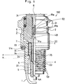
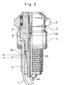
- the spark plug 100 has a cylindrical metallic shell 2, to a front end of which an L-shaped ground electrode 1 is fixed and attached by means of welding.
- a tubular insulator 3 Within the metallic shell 2, is a tubular insulator 3, an inner space of which serves as an axial bore 31.
- a centre electrode 4 Concentrically within the bore 31, is a centre electrode 4.
- the outer surface of the metallic shell 2 has a diameter-increased hexagonal head 21, a barrel portion 22 and a threaded portion 23 which is to be attached to a cylinder block of an internal combustion engine.
- Each inner diameter of the hexagonal head 21 and the barrel portion 22 are larger, while an inner diameter of the threaded portion 23 is smaller.
- An inner wall of the region of the metallic shell 2 that is inside the threaded portion 23 has a shoulder portion 24 on which a stepped portion 3a rests by way of a gasket 25.
- the stepped portion 3a rests by way of a gasket 25.
- the stepped portion 3a is provided on the insulator 3 to support the insulator 3 within the metallic shell 2.
- the shoulder portion 24 includes an upper shoulder and lower shoulder as indicated at (a), (b) in Fig. 1.
- the insulator 3 has a tapered leg portion 32, a diameter-increased portion 33 and a head 35 whose outer surface has a corrugation 34. Between the diameter-increased portion 33 and the leg portion 32, is a middle portion 36 which is diametrically somewhat larger than the leg portion 32.
- the insulator 3 has a rear half 6 made of aluminium oxide (Al203) and a front half 5 made of aluminium nitride (AlN) so as to form a split-type insulator.
- the front half 5 includes the middle portion 36.
- a cylindrical recess 51 which extends into the leg portion 32 in such a manner that the rear portion of the front half 5 forms a housing 51a around the recess 51.
- the rear half 6 includes the diameter-increased portion 33 whose front end integrally has a protrusion 61.
- the protrusion 61 is air-tightly joined to the housing 51a by means of a heat-resistant adhesive (a silicon resin) or a glass sealant 7.
- an overlapping portion (Op) of the protrusion 61 and the housing 51a is at least partly located in coplanar relationship with the upper and lower shoulders (a), (b) as apparent from Figs. 1, 2.
- the center electrode 4 is inserted into the axial bore 31 whose inner wall has a ledge portion 31a.
- the center electrode has a flange head 4B which rests on the ledge portion 31a to bring the rear half 6 into a tight engagement with an inner wall of the housing 51a.
- a terminal 83 and a middle axis 8 connected by way of a monolithic resistor 82 interposed between conductive glass seals 81a, 81b.
- a front end of the spark plug 100 is, in use, projected into a combustion chamber on a internal combustion engine.
- a spark discharge is likely to occur between the center electrode 4 and the metallic shell 2 across the portion of the insulator where the shoulder portion directly meets the insulator, perhaps from the upper and lower shoulders (a), (b) or from the corners of the shoulder portion 24, if the insulator is poor in withstanding the high voltage.
- the Al203-made protrusion 61 which is superior in withstanding the high voltage, is of such a length as to extend past the coplanar line which the lower shoulder (b) forms i.e.(d) is below (b) in Fig. 1.
- the housing 51a is located, which is made of aluminium nitride (AlN), which is superior in heat conductivity to aluminium oxide (Al203) of which the rear half 6 is made.
- the heat developed in the front end of 4A of the spark plug 100 may be more favourably dissipated to the metallic shell 2, by way of the front half 5, the gasket 25, the stepped portion 31a and the shoulder portion 24, than if the insulator is made entirely of aluminium oxide (Al203).
- the insulator is more capable of withstanding a high voltage than if the insulator is made entirely of aluminium nitride (AlN), because the protrusion extends past the shoulder portion 24 to which a spark discharge is likely to occur. Even if the thickness of the housing is reduced, it is possible to protect against a spark discharge by increasing the diameter of the protrusion 61.
- the adhesive 7 used at the joining surface between the protrusion 61 and the housing 51a is a glass sealant or a synthetic resin which also resists the high voltage.
- the glass sealant is very fine, and has a good wetting relationship with the protrusion 61 and the housing 51a.
- the coefficient of thermal expansion of the glass sealant is preferably 5 ⁇ 8 x 10 ⁇ 6 K ⁇ 1 which is intermediate between that of aluminium nitride (AlN) and that of aluminium oxide (Al203) .
- the protrusion 61 When using a glass sealant which has a high softening point, the protrusion 61 is generally joined to the housing 51a by means of the glass sealant, prior to thermally encapsulating the conductive glass seals 81a, 81b, the monolithic resistor 82 and the terminal 83 into the insulator 3 (prior joint system).
- a heat-resistant glass sealant When using the prior joint system, it is necessary to use a heat-resistant glass sealant so that it is not melted when thermally encapsulating or hot pressing the conductive glass seals 81a, 81b, the monolithic resistor 82 and the terminal 83.
- the protrusion 61 When using the glass sealant which has a intermediate softening point, the protrusion 61 is generally joined to the housing 51a by means of the glass sealant, and simultaneously thermally encapsulating the conductive glass seals 81a. 81b, the monolithic resistor 82 and the terminal 83 into the insulator 3 (simultaneous joint system).
- the simultaneous joint system it is necessary to use a heat-resistant glass sealant having a softening point similar to the glass seals.
- the protrusion 61 is joined to the housing 51a by means of the glass sealant after thermally encapsulating the conductive glass seals 81a, 81b, the monolithic resistor 82 and the terminal 83 into the insulator 3 (post joint system).
- the post joint system enables the use of inexpensive resin when the joint portion is used n a sufficiently low temperature ambience.
- the adhesive needs high voltage resistance and high insulation properties.
- a spark-endurance experiment was carried out at full load and 5000 rpm for 100 hours with the spark plug mounted on a four-cylinder, 2000 cc engine the joint system, the adhesive and the spark plug dimensions. Results of the experiment are shown in the Table. Figs. 4a ⁇ 4f shows counterpart spark plugs as examples how a spark discharge occurs across the insulator.
- the protrusion 61 is fitted into the recess 51 deeply as shown by a distance between (c) and (d) in Fig. 1.
- the overlapping portion of the protrusion 61 and the housing 51a is exposed to a high temperature ambience, a glass sealant having a high or intermediate softening point is used as an adhesive.
- the protrusion 61 is not fitted so deeply into the recess 51, the overlapping portion of the protrusion 61 and the housing 51a is not exposed to as high a temperature ambience and a glass sealant having a synthetic resin or a low softening point is used as an adhesive.
- specimen (E) of the invention the protrusion 61 is not fitted so deeply into the recess 51 and the simultaneous system is adopted. It is found in any specimens (A) to (E) that no spark discharge penetrates across the insulator during the 100 hour-experiment.
- the front half 5 made of aluminium nitride which is inexpensive and superior in heat-conductivity in order to quickly transmit the heat of the front end of the spark plug, while the rear half is made of aluminium oxide which is superior in withstanding high voltage.
- the heat-resistant adhesive 7 which is superior in insulation, is used as an adhesive between the protrusion 61 and the housing 51a. This enables to provide an economic and reliable spark plug which is capable of preventing a spark discharge from penetrating across the insulator.
- a male thread may be made on an outer surface of the protrusion 61 and a female thread made on an inner wall of the housing 51a so that the protrusion 61 may be screwed into the housing 51a in order to integrate the protrusion 61 into the housing 51a.
- a glass sealant may be used instead of the heat-resistant adhesive.
Landscapes
- Spark Plugs (AREA)
Applications Claiming Priority (2)
| Application Number | Priority Date | Filing Date | Title |
|---|---|---|---|
| JP13211/92 | 1992-01-28 | ||
| JP4013211A JP2625307B2 (ja) | 1992-01-28 | 1992-01-28 | スパークプラグ |
Publications (2)
| Publication Number | Publication Date |
|---|---|
| EP0554045A1 true EP0554045A1 (de) | 1993-08-04 |
| EP0554045B1 EP0554045B1 (de) | 1995-12-27 |
Family
ID=11826824
Family Applications (1)
| Application Number | Title | Priority Date | Filing Date |
|---|---|---|---|
| EP93300545A Expired - Lifetime EP0554045B1 (de) | 1992-01-28 | 1993-01-26 | Zündkerze |
Country Status (4)
| Country | Link |
|---|---|
| US (1) | US5477104A (de) |
| EP (1) | EP0554045B1 (de) |
| JP (1) | JP2625307B2 (de) |
| DE (1) | DE69301097T2 (de) |
Cited By (3)
| Publication number | Priority date | Publication date | Assignee | Title |
|---|---|---|---|---|
| WO2009046687A1 (en) * | 2007-10-08 | 2009-04-16 | Towit Machinery Trading Ag. | Sapphire sparking plug and method of its manufacture |
| CN102057547A (zh) * | 2008-04-10 | 2011-05-11 | 费德罗-莫格尔点火公司 | 陶瓷火花塞绝缘体及其制造方法 |
| EP2383847B1 (de) * | 2008-12-25 | 2019-09-18 | Ngk Spark Plug Co., Ltd. | Zündkerze |
Families Citing this family (9)
| Publication number | Priority date | Publication date | Assignee | Title |
|---|---|---|---|---|
| JP3813708B2 (ja) * | 1996-09-12 | 2006-08-23 | 日本特殊陶業株式会社 | スパークプラグの製造方法 |
| US6357408B1 (en) * | 2000-03-31 | 2002-03-19 | Bombardier Motor Corporation Of America | System and method for eliminating pocket sparking in an internal combustion engine |
| EP2131036B1 (de) * | 2007-03-22 | 2014-07-30 | Ngk Spark Plug Co., Ltd. | Zündkerze |
| US8667824B2 (en) * | 2010-11-05 | 2014-03-11 | Ford Global Technologies, Llc | Electrode assembly for electro-hydraulic forming process |
| CN102856792B (zh) * | 2012-09-10 | 2014-03-26 | 株洲湘火炬火花塞有限责任公司 | 复合氧化铝绝缘体火花塞及其制造方法 |
| US9835127B2 (en) * | 2013-05-30 | 2017-12-05 | Nissan Motor Co., Ltd. | Internal combustion engine ignition device and ignition method |
| US10008831B2 (en) * | 2015-03-26 | 2018-06-26 | Federal-Mogul Llc | Corona suppression at materials interface through gluing of the components |
| JP6419109B2 (ja) * | 2016-06-08 | 2018-11-07 | 日本特殊陶業株式会社 | プラズマジェットプラグ |
| JP2020080280A (ja) * | 2018-11-14 | 2020-05-28 | 日本特殊陶業株式会社 | 点火プラグ及び点火プラグの製造方法 |
Citations (2)
| Publication number | Priority date | Publication date | Assignee | Title |
|---|---|---|---|---|
| DE861180C (de) * | 1938-07-02 | 1952-12-29 | Bosch Gmbh Robert | Verfahren zur Herstellung von Steinisolatoren, die aus Einzelteilen zusammengesetzt sind, insbesondere von Zuendkerzensteinen |
| EP0349183A1 (de) * | 1988-06-21 | 1990-01-03 | Ngk Spark Plug Co., Ltd | Zündkerze |
Family Cites Families (12)
| Publication number | Priority date | Publication date | Assignee | Title |
|---|---|---|---|---|
| US2053369A (en) * | 1931-06-24 | 1936-09-08 | Champion Spark Plug Co | Spark plug and method of making the same |
| US2217825A (en) * | 1939-08-25 | 1940-10-15 | Champion Spark Plug Co | Spark plug |
| US2356053A (en) * | 1941-05-14 | 1944-08-15 | Jr Arthur C Hastings | Spark plug |
| US2483357A (en) * | 1944-08-30 | 1949-09-27 | Ulf Karl Richard Bergild | Spark plug |
| US2458121A (en) * | 1945-06-23 | 1949-01-04 | Bendix Aviat Corp | Radio shielded ignition means |
| US2576176A (en) * | 1946-05-08 | 1951-11-27 | Bendix Aviat Corp | Spark plug assembly |
| US2863080A (en) * | 1955-04-15 | 1958-12-02 | Gen Motors Corp | Spark plug and method for making same |
| US2937296A (en) * | 1959-02-12 | 1960-05-17 | Bendix Aviat Corp | Spark discharge device |
| US3344304A (en) * | 1965-06-23 | 1967-09-26 | Gen Motors Corp | Creepage spark type plug having low voltage igniter seal |
| US3745400A (en) * | 1972-03-23 | 1973-07-10 | Bendix Corp | Igniter plug |
| DE3616668A1 (de) * | 1986-05-16 | 1987-11-19 | Bosch Gmbh Robert | Zuendkerze mit gleitfunkenstrecke |
| GB2241739B (en) * | 1990-03-09 | 1994-11-23 | Cooper Ind Inc | Igniter and cable connector assembly |
-
1992
- 1992-01-28 JP JP4013211A patent/JP2625307B2/ja not_active Expired - Lifetime
-
1993
- 1993-01-26 EP EP93300545A patent/EP0554045B1/de not_active Expired - Lifetime
- 1993-01-26 DE DE69301097T patent/DE69301097T2/de not_active Expired - Fee Related
-
1994
- 1994-11-10 US US08/338,829 patent/US5477104A/en not_active Expired - Fee Related
Patent Citations (2)
| Publication number | Priority date | Publication date | Assignee | Title |
|---|---|---|---|---|
| DE861180C (de) * | 1938-07-02 | 1952-12-29 | Bosch Gmbh Robert | Verfahren zur Herstellung von Steinisolatoren, die aus Einzelteilen zusammengesetzt sind, insbesondere von Zuendkerzensteinen |
| EP0349183A1 (de) * | 1988-06-21 | 1990-01-03 | Ngk Spark Plug Co., Ltd | Zündkerze |
Cited By (4)
| Publication number | Priority date | Publication date | Assignee | Title |
|---|---|---|---|---|
| WO2009046687A1 (en) * | 2007-10-08 | 2009-04-16 | Towit Machinery Trading Ag. | Sapphire sparking plug and method of its manufacture |
| CN102057547A (zh) * | 2008-04-10 | 2011-05-11 | 费德罗-莫格尔点火公司 | 陶瓷火花塞绝缘体及其制造方法 |
| CN102057547B (zh) * | 2008-04-10 | 2013-06-12 | 费德罗-莫格尔点火公司 | 陶瓷火花塞绝缘体及其制造方法 |
| EP2383847B1 (de) * | 2008-12-25 | 2019-09-18 | Ngk Spark Plug Co., Ltd. | Zündkerze |
Also Published As
| Publication number | Publication date |
|---|---|
| JPH05205847A (ja) | 1993-08-13 |
| DE69301097T2 (de) | 1996-05-15 |
| DE69301097D1 (de) | 1996-02-08 |
| JP2625307B2 (ja) | 1997-07-02 |
| US5477104A (en) | 1995-12-19 |
| EP0554045B1 (de) | 1995-12-27 |
Similar Documents
| Publication | Publication Date | Title |
|---|---|---|
| EP0554045B1 (de) | Zündkerze | |
| US20080218053A1 (en) | 14 mm extension spark plug | |
| US7243643B2 (en) | Ignition device for internal combustion engine | |
| JPS633424B2 (de) | ||
| US12027825B1 (en) | Spark plug and method for producing a spark plug | |
| US8384278B2 (en) | Leadless package housing having an insulator and composition | |
| JPH11329666A (ja) | スパークプラグ | |
| US6819030B2 (en) | Spark plug | |
| EP0989369B1 (de) | Glühensensor- und - Motorteilkombination | |
| EP1249907B1 (de) | Befestigungsanordnung einer Zündkerze und Zündkerze dafür | |
| US20100007257A1 (en) | Spark Plug | |
| JP4068381B2 (ja) | スパークプラグの取付構造 | |
| US4506186A (en) | Spark plug and optical combustion sensor combination | |
| JPH02109286A (ja) | 内燃機関用スパークプラグ | |
| JP6775460B2 (ja) | 点火プラグ | |
| US3417276A (en) | Spark plugs | |
| JPH06196247A (ja) | 内燃機関用スパークプラグ | |
| JP6291110B1 (ja) | スパークプラグ | |
| RU2007004C1 (ru) | Полупроводниковая свеча зажигания | |
| JP4480294B2 (ja) | スパークプラグの取付構造及びスパークプラグ | |
| RU2028023C1 (ru) | Полупроводниковая свеча зажигания для газотурбинного двигателя | |
| JP2022026238A (ja) | 内燃機関用のスパークプラグ | |
| JPH0445730B2 (de) | ||
| JPH06101366B2 (ja) | 内燃機関用スパークプラグ | |
| JPH0227679A (ja) | 内燃機関用スパークプラグ |
Legal Events
| Date | Code | Title | Description |
|---|---|---|---|
| PUAI | Public reference made under article 153(3) epc to a published international application that has entered the european phase |
Free format text: ORIGINAL CODE: 0009012 |
|
| AK | Designated contracting states |
Kind code of ref document: A1 Designated state(s): DE FR GB IT |
|
| 17P | Request for examination filed |
Effective date: 19931222 |
|
| 17Q | First examination report despatched |
Effective date: 19940915 |
|
| GRAA | (expected) grant |
Free format text: ORIGINAL CODE: 0009210 |
|
| AK | Designated contracting states |
Kind code of ref document: B1 Designated state(s): DE FR GB IT |
|
| REF | Corresponds to: |
Ref document number: 69301097 Country of ref document: DE Date of ref document: 19960208 |
|
| ITF | It: translation for a ep patent filed | ||
| ET | Fr: translation filed | ||
| PLBE | No opposition filed within time limit |
Free format text: ORIGINAL CODE: 0009261 |
|
| STAA | Information on the status of an ep patent application or granted ep patent |
Free format text: STATUS: NO OPPOSITION FILED WITHIN TIME LIMIT |
|
| 26N | No opposition filed | ||
| REG | Reference to a national code |
Ref country code: GB Ref legal event code: IF02 |
|
| PGFP | Annual fee paid to national office [announced via postgrant information from national office to epo] |
Ref country code: FR Payment date: 20030110 Year of fee payment: 11 |
|
| PGFP | Annual fee paid to national office [announced via postgrant information from national office to epo] |
Ref country code: GB Payment date: 20030122 Year of fee payment: 11 |
|
| PGFP | Annual fee paid to national office [announced via postgrant information from national office to epo] |
Ref country code: DE Payment date: 20030206 Year of fee payment: 11 |
|
| PG25 | Lapsed in a contracting state [announced via postgrant information from national office to epo] |
Ref country code: GB Free format text: LAPSE BECAUSE OF NON-PAYMENT OF DUE FEES Effective date: 20040126 |
|
| PG25 | Lapsed in a contracting state [announced via postgrant information from national office to epo] |
Ref country code: DE Free format text: LAPSE BECAUSE OF NON-PAYMENT OF DUE FEES Effective date: 20040803 |
|
| GBPC | Gb: european patent ceased through non-payment of renewal fee |
Effective date: 20040126 |
|
| PG25 | Lapsed in a contracting state [announced via postgrant information from national office to epo] |
Ref country code: FR Free format text: LAPSE BECAUSE OF NON-PAYMENT OF DUE FEES Effective date: 20040930 |
|
| REG | Reference to a national code |
Ref country code: FR Ref legal event code: ST |
|
| PG25 | Lapsed in a contracting state [announced via postgrant information from national office to epo] |
Ref country code: IT Free format text: LAPSE BECAUSE OF NON-PAYMENT OF DUE FEES;WARNING: LAPSES OF ITALIAN PATENTS WITH EFFECTIVE DATE BEFORE 2007 MAY HAVE OCCURRED AT ANY TIME BEFORE 2007. THE CORRECT EFFECTIVE DATE MAY BE DIFFERENT FROM THE ONE RECORDED. Effective date: 20050126 |