EP0551971A1 - Utilisation d'un système d'attachement - Google Patents
Utilisation d'un système d'attachement Download PDFInfo
- Publication number
- EP0551971A1 EP0551971A1 EP93250003A EP93250003A EP0551971A1 EP 0551971 A1 EP0551971 A1 EP 0551971A1 EP 93250003 A EP93250003 A EP 93250003A EP 93250003 A EP93250003 A EP 93250003A EP 0551971 A1 EP0551971 A1 EP 0551971A1
- Authority
- EP
- European Patent Office
- Prior art keywords
- adhesive
- metal
- adhesive system
- strips
- attached
- Prior art date
- Legal status (The legal status is an assumption and is not a legal conclusion. Google has not performed a legal analysis and makes no representation as to the accuracy of the status listed.)
- Withdrawn
Links
Images


Classifications
-
- H—ELECTRICITY
- H02—GENERATION; CONVERSION OR DISTRIBUTION OF ELECTRIC POWER
- H02B—BOARDS, SUBSTATIONS OR SWITCHING ARRANGEMENTS FOR THE SUPPLY OR DISTRIBUTION OF ELECTRIC POWER
- H02B1/00—Frameworks, boards, panels, desks, casings; Details of substations or switching arrangements
- H02B1/26—Casings; Parts thereof or accessories therefor
- H02B1/30—Cabinet-type casings; Parts thereof or accessories therefor
Definitions
- Textile fasteners based on Velcro fastener elements are known for connecting parts of clothing or footwear. It is also known to use Velcro fasteners of this type also for fastening rigid bodies to solid supports or wall surfaces (DE-A-40 12 613, DE-A-40 07 586).
- the invention has for its object to more efficiently attach parts of electrical cabinets or switchgear cabinets consisting of such cabinets than has previously been done by screws, locking bolts or similar elements.
- this object is achieved by using an adhesive system consisting of two strips which can be placed one on top of the other and which are to be fixedly attached to the components to be connected and which have a large number of flexible elements which can be releasably brought into engagement with one another for fastening outer covering components a control cabinet with scaffolding.
- an adhesive system consisting of two strips which can be placed one on top of the other and which are to be fixedly attached to the components to be connected and which have a large number of flexible elements which can be releasably brought into engagement with one another for fastening outer covering components a control cabinet with scaffolding.
- the flat or even strip-shaped fastening of the components counteracts a tendency to vibrate, as can occur especially in switch cabinets or switchgear under the influence of magnetic stray fields or the vibrations emanating from the operation of switching devices.
- a seal can be achieved with a suitable attachment of the strip-shaped strips of the adhesive system.
- An electrical connection between a cabinet or system frame and covering components can also be provided if a metallized or metal-containing one or is used in a different way with a conductive system (e.g. by means of graphite), as has become known, for example, from DE-A-34 03 258.
- the component can be, for example, a side wall, a rear wall or a roof plate of a control cabinet.
- a side wall is relatively large and therefore requires a large number of fastening elements in the usual construction of a control cabinet. These can be advantageously replaced by the adhesive system.
- the component can be a cover which closes a base of the control cabinet at the front.
- the front cover can be removed without loosening the fastening elements, but only by exerting a considerable force.
- the adhesive system can be used in such a way that the component is a panel that partially covers the front of a door of the control cabinet.
- the panel can be designed to be angular in cross-section and one band of the adhesive system can be attached to an upper edge of the door and the other band to a leg of the panel resting on the edge. In this way it is possible to raise the panel to read a label that is protected underneath. When you let go the panel returns to the starting position, in which the lettering is hidden.
- the carrier strips of the adhesive system are included in the corrosion protection. This also improves the durability of the self-adhesive adhesive layers between the metal strips and the framework or a cover and between the carrier strips of the adhesive system and the metal strips, because these adhesive layers are sealed at the edges by the coating.
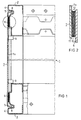
- Figure 1 shows the side area of a control cabinet in section.
- FIG. 1 A detail marked with a circle in FIG. 1 is shown enlarged in FIG.
- FIG. 3 shows a control cabinet in a perspective view.
- FIG. 4 shows a panel for the door of the control cabinet according to FIG. 3 in the folded-up state.
- FIG. 5 shows schematically and enlarged the application of a metal strip to a scaffold or a cover as an adhesive base for a conductive adhesive system.
- FIG. 6 shows the arrangement according to FIG. 1 when a protective film is removed.
- FIG. 7 also shows schematically and enlarged the application of a metal band and a band of an adhesive system to a frame or a cover with a covering lacquer and powder coating.
- the section through the side wall area of a control cabinet 1 is shown shortened in FIG. 1 by an interruption in height.
- An upper scaffold element 2 and a lower, mirror-image scaffold element 3 correspond in profile to the scaffold elements described in DE-A-39 20 353.
- the scaffolding elements 2 and 3 starting from an outer partial surface 4, have a retraction 5 and a further partial surface 6 arranged recessed relative to the partial surface 4.
- the bands of an adhesive system are attached to the partial surfaces 6 of the framework elements 2 and 3 and the opposite inner surfaces 7a of the cover 7.
- the structure of the adhesive system can be seen in more detail on the basis of the region shown enlarged in FIG. 2, which is surrounded by a dash-dotted circle in FIG.
- a band 10 is attached to the partial surface 6 and a band 11 is attached to the opposite surface of the side wall 7.
- These are preferably the strip-shaped tapes of a known adhesive system based on the Velcro principle. It is basically irrelevant which part of the loop part and which part of the hooking part is attached.
- the tapes 10 and 11 are also attached in a known manner by means of self-adhesive adhesive layers.
- Such adhesive layers 12 are shown schematically in FIG. 2.
- FIGS. 1 and 2 An arrangement corresponding to FIGS. 1 and 2 can also be used analogously for fastening a front-side plinth panel of a control cabinet.
- the only difference from the application in the area of the side wall of the control cabinet is the dimensions and the position Of the parts.
- a base panel 16 is shown in FIG. 3.
- the advantageous properties of the fastening of covers described include, in particular, that the outer surface of the covers is not interrupted by fastening elements. Although this could also be achieved with a fastening from the inside of the control cabinet, this would only require a great deal of work due to the unfavorable accessibility of the fastening points. A removal of cover parts fastened in this way would then no longer be possible with the control cabinet fully removed because there is no longer any access to the fastening elements.
- the door 21 of a cabinet 20 is provided at the upper edge with a decorative strip 22, which can itself be provided with a label and which at the same time to protect a label attached to the door 21, for. B. can serve a nameplate.
- the decorative strip 22 is of an angular design and accordingly has a front leg 23 and one for Rest on a bevel 24 of the door 21 provided legs 25.
- the bands 26 and 27 of an adhesive system of the type described are attached. This makes it possible to release the liability by lifting the trim strip 22 in the direction of the arrow 28 and to read the lettering underneath.
- the decorative strip 22 moves hinge-like to its starting position, in which the lettering on the door 21 is covered.
- FIGS. 5 and 6 in which a sheet metal part 30 is shown, which can be part of a framework or a cover.
- a thin metal strip 31 is applied, for. B. a tinned thin copper tape.
- An electrically conductive self-adhesive layer 32 fastens the metal strip 31 and at the same time ensures the electrical connection to the sheet metal part 30.
- the metal strip is covered with a removable protective film 33.
- the protective film 33 is narrower than the metal strip 31, so that edge strips 34 remain uncovered. If the arrangement described is now provided with a corrosion-resistant coating 35 of the type mentioned, the metal strip 31 and its protective film 33 are also covered by the coating 35, as shown in FIG. 5.
- the protective film 33 can now be removed, the coating 35 tearing open.
- the edge strips 34 of the metal strip 31, however, remain covered by the coating 35, so that in particular the laterally exposed areas of the adhesive layer 32 and the bare metal surface of the sheet metal part 30 located underneath remain protected.
- Figure 6 shows this state.
- a metal strip 31 is first attached to the bare metal surface of the sheet metal part 30 by means of a self-adhesive adhesive layer 32.
- a tape 36 of a conductive adhesive system is now applied to the metal tape 31 by means of a further self-adhesive conductive adhesive layer 37.
- a carrier tape 40 which is wider than the actual adhesion-promoting layer 41, is essential for the tape 36.
- the adhesion-promoting layer 41 is covered by a protective film 42 which extends down to the carrier tape 40, but leaves edge strips 43 of the latter free.
- a continuous layer 44 is formed, which can be removed locally by pulling off the protective film 42. As a result, essentially only the adhesion-promoting layer 41 of the band 36 is exposed. The transitions from the sheet metal part 30 to the metal strip 31 and from this to the carrier strip 40 remain protected against corrosive and other influences.
Landscapes
- Engineering & Computer Science (AREA)
- Power Engineering (AREA)
- Casings For Electric Apparatus (AREA)
- Patch Boards (AREA)
Applications Claiming Priority (2)
| Application Number | Priority Date | Filing Date | Title |
|---|---|---|---|
| DE4201296 | 1992-01-16 | ||
| DE19924201296 DE4201296C2 (de) | 1992-01-16 | 1992-01-16 | Verwendung eines Haftsystems |
Publications (1)
| Publication Number | Publication Date |
|---|---|
| EP0551971A1 true EP0551971A1 (fr) | 1993-07-21 |
Family
ID=6449814
Family Applications (1)
| Application Number | Title | Priority Date | Filing Date |
|---|---|---|---|
| EP93250003A Withdrawn EP0551971A1 (fr) | 1992-01-16 | 1993-01-06 | Utilisation d'un système d'attachement |
Country Status (2)
| Country | Link |
|---|---|
| EP (1) | EP0551971A1 (fr) |
| DE (1) | DE4201296C2 (fr) |
Cited By (4)
| Publication number | Priority date | Publication date | Assignee | Title |
|---|---|---|---|---|
| WO1998023012A1 (fr) * | 1996-11-19 | 1998-05-28 | Rittal-Werk Rudolf Loh Gmbh & Co. Kg | Armoire de distribution |
| EP0902515A1 (fr) * | 1997-09-15 | 1999-03-17 | Schneider Electric Sa | Armoire à bandeau de personnalisation pour appareils électriques |
| DE202007007306U1 (de) * | 2007-05-23 | 2008-05-21 | Meusburger Georg Gmbh & Co. | Abdeckplatte für das Auswerferpaket einer Spritzgussform |
| EP2128944A1 (fr) * | 2008-10-27 | 2009-12-02 | ABB Technology AG | Procédé de production d'un appareil électrique encapsulé et ledit appareil électrique encapsulé |
Families Citing this family (5)
| Publication number | Priority date | Publication date | Assignee | Title |
|---|---|---|---|---|
| DE19500739C2 (de) * | 1995-01-12 | 1996-12-12 | Wilhelm Bader | Schrank für den Anlagen- oder Maschinenbau |
| DE19536904C1 (de) * | 1995-10-04 | 1996-11-21 | Loh Kg Rittal Werk | Schaltschrank mit Rahmengestell, Wandelementen und Schranktür |
| DE102005061336A1 (de) * | 2005-12-21 | 2007-06-28 | Rohde & Schwarz Gmbh & Co. Kg | Gehäuse zur Abschirmung von elektromagnetischen Störungen |
| DE102006047974A1 (de) * | 2006-10-10 | 2008-04-17 | Siemens Ag | Elektrobauteil |
| DE102007001656B3 (de) * | 2007-01-11 | 2008-07-24 | Howaldtswerke-Deutsche Werft Gmbh | Unterseeboot mit einem Schaltschrank |
Citations (6)
| Publication number | Priority date | Publication date | Assignee | Title |
|---|---|---|---|---|
| US3571999A (en) * | 1969-07-02 | 1971-03-23 | John G Downing | Knockdown display |
| DE2455240A1 (de) * | 1974-11-22 | 1976-05-26 | Bolle Friedrich Adolf Dipl Ing | Baukonstruktion zur verbindung von bauelementen |
| US3971608A (en) * | 1975-04-17 | 1976-07-27 | Gans Charles C | Knock-down drawer unit |
| US4936410A (en) * | 1988-09-19 | 1990-06-26 | Howell Les P | Speaker cover |
| US4966421A (en) * | 1987-07-24 | 1990-10-30 | Craig Mengel | Method of and structure for the joining of substantially rigid parts together |
| DE4019121A1 (de) * | 1989-06-13 | 1991-01-10 | Suzuki Motor Co | Halterungsmechanismus fuer (motor)haubenisolator |
Family Cites Families (7)
| Publication number | Priority date | Publication date | Assignee | Title |
|---|---|---|---|---|
| DE3343098A1 (de) * | 1983-11-29 | 1985-06-05 | Dieter 7930 Ehingen Giessler | Spielzeugmoebel |
| DE3403258A1 (de) * | 1984-01-31 | 1985-08-01 | Gottlieb Binder GmbH & Co, 7038 Holzgerlingen | Textiler flaechen-haftverschluss |
| DE3911017A1 (de) * | 1989-04-05 | 1990-10-11 | Ensslin Gmbh & Co | Labor- oder werkstattmoebel |
| DE3913060A1 (de) * | 1989-04-21 | 1990-10-25 | Klaus Schueler | Halter fuer einzelblaetter |
| DE3920353A1 (de) * | 1989-06-19 | 1990-12-20 | Siemens Ag | Geruest fuer einen schaltschrank aus mehrfach abgewinkelten profilelementen mit einseitig offenem hohlprofil |
| DE4007586A1 (de) * | 1990-03-09 | 1991-09-12 | Sto Poraver Gmbh | Verfahren und vorrichtung zum aufbringen von fliesen-, putz- oder lackbeschichtungen bzw. dekorbelaegen auf waenden, decken o. dgl. |
| DE4012613A1 (de) * | 1990-04-20 | 1991-10-24 | Peter Josef Korzilius Soehne G | Keramische fliese und verfahren zu deren verlegen |
-
1992
- 1992-01-16 DE DE19924201296 patent/DE4201296C2/de not_active Expired - Fee Related
-
1993
- 1993-01-06 EP EP93250003A patent/EP0551971A1/fr not_active Withdrawn
Patent Citations (7)
| Publication number | Priority date | Publication date | Assignee | Title |
|---|---|---|---|---|
| US3571999A (en) * | 1969-07-02 | 1971-03-23 | John G Downing | Knockdown display |
| DE2455240A1 (de) * | 1974-11-22 | 1976-05-26 | Bolle Friedrich Adolf Dipl Ing | Baukonstruktion zur verbindung von bauelementen |
| US3971608A (en) * | 1975-04-17 | 1976-07-27 | Gans Charles C | Knock-down drawer unit |
| US4966421A (en) * | 1987-07-24 | 1990-10-30 | Craig Mengel | Method of and structure for the joining of substantially rigid parts together |
| US4966421B1 (fr) * | 1987-07-24 | 1993-04-06 | Mengel Craig | |
| US4936410A (en) * | 1988-09-19 | 1990-06-26 | Howell Les P | Speaker cover |
| DE4019121A1 (de) * | 1989-06-13 | 1991-01-10 | Suzuki Motor Co | Halterungsmechanismus fuer (motor)haubenisolator |
Cited By (6)
| Publication number | Priority date | Publication date | Assignee | Title |
|---|---|---|---|---|
| WO1998023012A1 (fr) * | 1996-11-19 | 1998-05-28 | Rittal-Werk Rudolf Loh Gmbh & Co. Kg | Armoire de distribution |
| AU725964B2 (en) * | 1996-11-19 | 2000-10-26 | Rittal-Werk Rudolf Loh Gmbh & Co. Kg | Switchgear cabinet |
| US6211466B1 (en) | 1996-11-19 | 2001-04-03 | Rittal-Werk Rudolf Loh Gmbh & Co. Kg | Switching cabinet |
| EP0902515A1 (fr) * | 1997-09-15 | 1999-03-17 | Schneider Electric Sa | Armoire à bandeau de personnalisation pour appareils électriques |
| DE202007007306U1 (de) * | 2007-05-23 | 2008-05-21 | Meusburger Georg Gmbh & Co. | Abdeckplatte für das Auswerferpaket einer Spritzgussform |
| EP2128944A1 (fr) * | 2008-10-27 | 2009-12-02 | ABB Technology AG | Procédé de production d'un appareil électrique encapsulé et ledit appareil électrique encapsulé |
Also Published As
| Publication number | Publication date |
|---|---|
| DE4201296C2 (de) | 1995-10-19 |
| DE4201296A1 (de) | 1993-07-22 |
Similar Documents
| Publication | Publication Date | Title |
|---|---|---|
| DE4127468C1 (fr) | ||
| DE4223322C1 (fr) | ||
| EP0857406B1 (fr) | Armoire de distribution etanche aux hautes frequences | |
| DE2608921A1 (de) | Abschirmstreifen fuer elektromagnetische stoerungen | |
| DE2134815A1 (de) | Gehäuseanordnung für elektrische Geräte zur Abschirmung gegen elektrostatische und magnetostatische Strahlen | |
| DE19700065C2 (de) | Filterlüfter oder Austrittsfilter | |
| EP2638606A2 (fr) | Armoire de commande électrique | |
| DE4311246C1 (de) | Gehäuse für elektronische Geräte | |
| DE1195829C2 (de) | Elektrisches geraetechassis und verfahren zu seiner herstellung | |
| EP0133555A2 (fr) | Blindage contre des rayonnements à haute fréquence de surfaces planes | |
| DE3635866C2 (de) | Plattenhalter | |
| DE2424722B2 (de) | Gehäuse für Geräte der elektrischen MeB- und Nachrichtentechnik | |
| EP0551971A1 (fr) | Utilisation d'un système d'attachement | |
| DE7903580U1 (de) | Magazin fuer magnetbandkassetten | |
| DE69817259T2 (de) | Elektronische Abschirmung und Leiterplatte mit einer solchen Abschirmung | |
| EP0838987B1 (fr) | Baie électronique | |
| DE19644414C1 (de) | Abgeschirmter Baugruppenträger | |
| DE19548723A1 (de) | Gehäuse zur Aufnahme von elektronischen Bauelementen | |
| DE19908889A1 (de) | Elektronikgehäuse mit verbesserter Abdicht- und Abschirmvorrichtung und Verfahren zum Herstellen desselben | |
| EP0269126B1 (fr) | Boîtier blindé | |
| DE1690003C3 (de) | Zerlegbarer Kasten zur Unterbringung elektrischer Geräte | |
| DE4207308C2 (de) | Verfahren zum Herstellen eines Blechgehäuses | |
| DE4402235C2 (de) | Schutzdeckel | |
| DE19629230A1 (de) | Elektronisches Gerät sowie Abschirm-Formteil für ein elektronisches Gerät | |
| DE2300576A1 (de) | Gegen elektromagnetische strahlung abschirmende verbindung zwischen zwei metallteilen |
Legal Events
| Date | Code | Title | Description |
|---|---|---|---|
| PUAI | Public reference made under article 153(3) epc to a published international application that has entered the european phase |
Free format text: ORIGINAL CODE: 0009012 |
|
| AK | Designated contracting states |
Kind code of ref document: A1 Designated state(s): AT DE FR GB IT SE |
|
| 17P | Request for examination filed |
Effective date: 19931206 |
|
| 17Q | First examination report despatched |
Effective date: 19950714 |
|
| STAA | Information on the status of an ep patent application or granted ep patent |
Free format text: STATUS: THE APPLICATION HAS BEEN WITHDRAWN |
|
| 18W | Application withdrawn |
Withdrawal date: 19960129 |