EP0551491B1 - Elektromotorischer stellantrieb für eine zentrale türverriegelungsanlage eines kraftfahrzeugs - Google Patents
Elektromotorischer stellantrieb für eine zentrale türverriegelungsanlage eines kraftfahrzeugs Download PDFInfo
- Publication number
- EP0551491B1 EP0551491B1 EP92916936A EP92916936A EP0551491B1 EP 0551491 B1 EP0551491 B1 EP 0551491B1 EP 92916936 A EP92916936 A EP 92916936A EP 92916936 A EP92916936 A EP 92916936A EP 0551491 B1 EP0551491 B1 EP 0551491B1
- Authority
- EP
- European Patent Office
- Prior art keywords
- slide
- actuator according
- electromotive actuator
- electric motor
- latch
- Prior art date
- Legal status (The legal status is an assumption and is not a legal conclusion. Google has not performed a legal analysis and makes no representation as to the accuracy of the status listed.)
- Expired - Lifetime
Links
Images


Classifications
-
- E—FIXED CONSTRUCTIONS
- E05—LOCKS; KEYS; WINDOW OR DOOR FITTINGS; SAFES
- E05B—LOCKS; ACCESSORIES THEREFOR; HANDCUFFS
- E05B81/00—Power-actuated vehicle locks
- E05B81/24—Power-actuated vehicle locks characterised by constructional features of the actuator or the power transmission
- E05B81/25—Actuators mounted separately from the lock and controlling the lock functions through mechanical connections
-
- E—FIXED CONSTRUCTIONS
- E05—LOCKS; KEYS; WINDOW OR DOOR FITTINGS; SAFES
- E05B—LOCKS; ACCESSORIES THEREFOR; HANDCUFFS
- E05B85/00—Details of vehicle locks not provided for in groups E05B77/00 - E05B83/00
- E05B85/02—Lock casings
-
- Y—GENERAL TAGGING OF NEW TECHNOLOGICAL DEVELOPMENTS; GENERAL TAGGING OF CROSS-SECTIONAL TECHNOLOGIES SPANNING OVER SEVERAL SECTIONS OF THE IPC; TECHNICAL SUBJECTS COVERED BY FORMER USPC CROSS-REFERENCE ART COLLECTIONS [XRACs] AND DIGESTS
- Y10—TECHNICAL SUBJECTS COVERED BY FORMER USPC
- Y10S—TECHNICAL SUBJECTS COVERED BY FORMER USPC CROSS-REFERENCE ART COLLECTIONS [XRACs] AND DIGESTS
- Y10S292/00—Closure fasteners
- Y10S292/03—Automobile multiple door latches
-
- Y—GENERAL TAGGING OF NEW TECHNOLOGICAL DEVELOPMENTS; GENERAL TAGGING OF CROSS-SECTIONAL TECHNOLOGIES SPANNING OVER SEVERAL SECTIONS OF THE IPC; TECHNICAL SUBJECTS COVERED BY FORMER USPC CROSS-REFERENCE ART COLLECTIONS [XRACs] AND DIGESTS
- Y10—TECHNICAL SUBJECTS COVERED BY FORMER USPC
- Y10S—TECHNICAL SUBJECTS COVERED BY FORMER USPC CROSS-REFERENCE ART COLLECTIONS [XRACs] AND DIGESTS
- Y10S292/00—Closure fasteners
- Y10S292/23—Vehicle door latches
-
- Y—GENERAL TAGGING OF NEW TECHNOLOGICAL DEVELOPMENTS; GENERAL TAGGING OF CROSS-SECTIONAL TECHNOLOGIES SPANNING OVER SEVERAL SECTIONS OF THE IPC; TECHNICAL SUBJECTS COVERED BY FORMER USPC CROSS-REFERENCE ART COLLECTIONS [XRACs] AND DIGESTS
- Y10—TECHNICAL SUBJECTS COVERED BY FORMER USPC
- Y10T—TECHNICAL SUBJECTS COVERED BY FORMER US CLASSIFICATION
- Y10T292/00—Closure fasteners
- Y10T292/08—Bolts
- Y10T292/096—Sliding
- Y10T292/1014—Operating means
- Y10T292/1021—Motor
-
- Y—GENERAL TAGGING OF NEW TECHNOLOGICAL DEVELOPMENTS; GENERAL TAGGING OF CROSS-SECTIONAL TECHNOLOGIES SPANNING OVER SEVERAL SECTIONS OF THE IPC; TECHNICAL SUBJECTS COVERED BY FORMER USPC CROSS-REFERENCE ART COLLECTIONS [XRACs] AND DIGESTS
- Y10—TECHNICAL SUBJECTS COVERED BY FORMER USPC
- Y10T—TECHNICAL SUBJECTS COVERED BY FORMER US CLASSIFICATION
- Y10T70/00—Locks
- Y10T70/50—Special application
- Y10T70/5889—For automotive vehicles
-
- Y—GENERAL TAGGING OF NEW TECHNOLOGICAL DEVELOPMENTS; GENERAL TAGGING OF CROSS-SECTIONAL TECHNOLOGIES SPANNING OVER SEVERAL SECTIONS OF THE IPC; TECHNICAL SUBJECTS COVERED BY FORMER USPC CROSS-REFERENCE ART COLLECTIONS [XRACs] AND DIGESTS
- Y10—TECHNICAL SUBJECTS COVERED BY FORMER USPC
- Y10T—TECHNICAL SUBJECTS COVERED BY FORMER US CLASSIFICATION
- Y10T70/00—Locks
- Y10T70/60—Systems
- Y10T70/625—Operation and control
- Y10T70/65—Central control
-
- Y—GENERAL TAGGING OF NEW TECHNOLOGICAL DEVELOPMENTS; GENERAL TAGGING OF CROSS-SECTIONAL TECHNOLOGIES SPANNING OVER SEVERAL SECTIONS OF THE IPC; TECHNICAL SUBJECTS COVERED BY FORMER USPC CROSS-REFERENCE ART COLLECTIONS [XRACs] AND DIGESTS
- Y10—TECHNICAL SUBJECTS COVERED BY FORMER USPC
- Y10T—TECHNICAL SUBJECTS COVERED BY FORMER US CLASSIFICATION
- Y10T70/00—Locks
- Y10T70/70—Operating mechanism
- Y10T70/7051—Using a powered device [e.g., motor]
- Y10T70/7062—Electrical type [e.g., solenoid]
- Y10T70/7113—Projected and retracted electrically
Definitions
- the invention relates to an electromotive actuator for a central door locking system of a motor vehicle, which actuator has the features from the preamble of claim 1.
- An electromotive actuator which has all the features from the preamble of claim 1 including the feature mentioned as being particularly advantageous, is known from DE-OS 36 27 893.
- This actuator has a z. B. from DE-OS 32 10 923 known electromotive actuator the advantage that the slide can also be easily adjusted manually from the end positions.
- the electric motor and the gears of the transmission connected downstream must be rotated when the slide is manually adjusted.
- the actuator shown in DE-OS 32 10 923 for a central door locking system of a motor vehicle not only allows central locking or unlocking of a motor vehicle door, but also a so-called anti-theft device.
- a central door locking system for a motor vehicle that is equipped with an anti-theft device a door lock can be locked and unlocked from the outside. This is also basically possible with a handle inside the motor vehicle. However, if the anti-theft device is set from the outside, it is no longer possible to unlock the door lock with the handle on the inside.
- the anti-theft device is realized in that the slide is locked against movement in the sense of unlocking by a pawl which can be pivoted by a second electric motor.
- This has various disadvantages. In the event of a break-in and an actuation of the handle inside the motor vehicle, parts within the actuator are exposed to high forces which can be exerted on them via the handle. If you do not want to accept damage, the parts must be designed accordingly strong.
- Another disadvantage is that a vehicle door can no longer be unlocked if the motor actuating the pawl fails for some reason in the anti-theft position.
- the invention has for its object to provide an electromotive actuator for a central door locking system of a motor vehicle, in which actuator an anti-theft device is provided without parts of the actuator being excessively loaded during an attempted break-in, and in which actuator manual unlocking from the outside is also then is possible if the anti-theft device cannot be reset by a motor.
- an electromotive actuator which, in addition to the features from the preamble, is also equipped with the features from the characterizing part of claim 1.
- a second slide is initially provided, which at least for unlocking the door lock with the handle inside the motor vehicle can be coupled.
- the second slide can be coupled to the first slide via a pawl which is guided on one of the two slides so as to be adjustable transversely to the direction of movement of the slide and which engages in the other slide under the action of a spring element.
- the two slides can be regarded as a single slider for the movement sequence, so that unlocking is readily possible from inside the motor vehicle.
- the pawl can be retracted by a second electric motor via a control element from the engagement in the other slide against the action of the spring element. This means that it is no longer possible to transmit motion from the second to the first slide, so that if the second slide is attempted to break in, whether the latch is now guided on it or on the first slide, the door lock cannot be unlocked.
- the forces introduced into the handle inside the motor vehicle do not have to be absorbed by parts of the actuator, since the second slide can be moved.
- the first slider regardless of whether the pawl is guided on it or not, can still lock in from the outside or from the first electric motor the unlocking position are brought.
- this also means that when unlocking the door lock from the anti-theft position of the pawl, a special sequence in the operation of the pawl and the displacement of the first slide need not be observed.
- the electromotive actuator according to claim 2 also provides a solution to the problem.
- This actuator also has a first slide, which can be connected in a direction-independent manner to a door lock of the motor vehicle, and a second slide, which can be coupled for unlocking with a handle inside a motor vehicle is. Both slides engage with a projection and a recess transversely to their direction of movement, a driver of one of the two sliders being movable relative to the slider in the direction of movement of the two slides to prevent theft of an electric motor to form a dead gear by reducing the projection or increasing the recess is. After the dead gear has been formed, the second slide can be opened again move freely from the handle inside the motor vehicle without taking the first slide with it and thus unlocking the door lock.
- An advantageous embodiment of an actuator according to claim 1 or 2 is contained in claim 3. Thereafter, a smooth manual adjustment of the first slide is possible without having to move the first electric motor and a gear arranged after it.
- the second slide can be taken from the first slide in the direction of unlocking independently of the pawl.
- the second slide can be taken along with the first slide from the outside without the anti-theft device having been reset by the second electric motor beforehand.
- the control member is a control cam with a ramp. From the basic mode of operation, it is unimportant whether the direction of movement of the ramp on the latch when it is retracted, that is to say when the anti-theft device is set, corresponds to the direction of the slide when locking or unlocking. However, it appears to be more advantageous if the ramp moves according to claim 7 when the pawl runs in such a direction that corresponds to the direction of movement of the slide when locking. A force is then not exerted on the pawl from the ramp in the direction of unlocking of the slides, so that there is no danger that the slides move somewhat out of the locking position and the setting of the anti-theft device is made difficult or not possible at all.
- the ramp of the control cam can happen to be in the path of the pawl, it is provided according to claim 9 that the ramp of the control curve is designed to be resilient in such a way that the pawl when the slide is adjusted from the unlocking position into the locking position under the ramp can be pushed or pushed under the ramp.
- a prerequisite for this spring characteristic of the ramp is, of course, that it is separated from its support at its base. Further advantageous embodiments to maintain the spring property of the ramp are set out in claims 10 and 11.
- the ramp at its foot should be separated from its carrier.
- the distance must not be large to ensure that the pawl runs onto the ramp.
- the foot of the ramp When shaping the control curve, which is usually injection molded with its carrier made of plastic, the foot of the ramp must therefore be separated from the carrier by a tool section which is as thin as possible. So that this thin tool section does not have to be so long, the ramp is thinner at its foot than at a distance from its foot.
- the control cam is preferably located on a gearwheel that can be driven by the second electric motor.
- the precautions against failure of the second electric motor can be implemented most easily when the control cam is arranged in such a way that the pawl can be moved by it in the direction of the axis of the gearwheel.
- the control curve advantageously has a plateau section without a change in height.
- the second electric motor continues to follow an indefinite path which, owing to the plateau section of the control curve, cannot affect the position of the pawl. If the pawl is guided on the second slide, it is brought into the unlocked position together with the second slide in an attempted theft.
- the handle When the handle is reset in the interior of the vehicle, it returns to the locking position with the second slide, again reaching the plateau section of the control curve.
- the plateau section according to claim 17 has on its radially outer edge a sloping slope in the radial direction.
- the gearwheel can also be driven by the electric motor in only one direction of rotation.
- the second electric motor can be switched on by the spring element both for pulling back the pawl and for pushing the pawl forward, the gear wheel then being able to be rotated through approximately 180 ° each time the electric motor is switched on.
- the pawl can be moved away from the control cam even when the anti-theft device is set, it is in principle not necessary for the second electric motor to be switched on to reset the anti-theft device.
- the second electric motor can only be switched on for pulling back the pawl, the gearwheel preferably being rotatable through 360 ° after each switching on of the electric motor.
- the number of switching operations and, if the gearwheel is rotated less than 360 ° in each case, the total operating time of the second electric motor can be reduced.
- only one opener is required as a limit switch, so that the number of electrical lines within the actuator can also be reduced.
- a time delay could, however, also be created in that the motors are switched on at the same time, but the gearwheel with the control cam runs much slower than the gearwheel with the crank adjusting the slide or, in the case that the gearwheel with the control cam, in each case by 360 ° is rotated, the ramp only comes to a pawl after an angle of rotation that is substantially greater than 180 °.
- the latter solutions are not very safe, since the length of time required for the slide to be adjusted by the first electric motor can vary considerably.
- the spring element of a coil spring which is located in a blind bore of the pawl and is supported on an extension of the pawl guiding the slide, which extension through a longitudinal slot in which the blind bore is open to the outside the blind hole protrudes.
- the jack is then very long and can be made correspondingly long.
- the path of the pawl out of its guidance is advantageously limited by a stop of the slide not guiding the pawl. A stop on the slide guiding the pawl is thereby avoided, so that the pawl is easily inserted into the guide can be.
- the coil spring is well supported laterally in each position of the pawl.
- the space available can make it appear favorable that the pawl is guided on the second slide according to claim 28. If, on the other hand, the pawl is guided on the first slide, it is not carried along when the anti-theft device is set and the handle inside the vehicle is actuated, which leads to a movement of the second slide, but remains on the control curve. There is no need to take precautions to ensure that the jack z. B. remains in the anti-theft position by a support surface on the first slide or on the housing or is pushed back into this position when the second slide returns.
- the whole construction of the lock, electromotive actuator and handle inside the vehicle and the mechanical connections between these parts can be chosen so that the second slide can only be actuated via the handle inside the vehicle in the sense of unlocking the door lock. So that a locking via the handle inside is possible, it is provided according to claim 31 that the slide can be coupled via a driver with the handle inside the motor vehicle and that the driver is in the direction of movement of the slide between them. If, on the other hand, the second slide can be actuated via the handle inside the motor vehicle both in terms of locking and in terms of unlocking, the second slide can advantageously be directly positively coupled to the driver in both directions of movement.
- the driver is advantageously movable according to claim 36 against the action of a spring element, which is supported on the associated slide. It also appears favorable if the driver can be coupled in one position to the associated slide by a limit force lock. Basically, this can be done in both operating positions of the driver in relation to the associated slide. When using a spring element, however, coupling by means of a limit force lock is only sufficient in one position, namely in that in which the projection is reduced or the recess is increased. Likewise, without a spring element, a single limit force lock in the named position of the driver is sufficient if an anti-theft device is also provided for each locking.
- An electromotive actuator according to claim 2 is particularly suitable for using only a single reversible electric motor for locking and theft protection, with which the driver is adjustably coupled.
- the coupling of the driver with the electric motor can, for. B. take place via a gear driven by the electric motor and a rack of the driver.
- the direction of rotation of the motor during anti-theft protection advantageously coincides with the direction of rotation during locking and during anti-theft protection advantageously corresponds to the direction of rotation during unlocking.
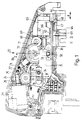
- a first electric motor 23 is fixed in a two-part housing 20 with a housing pot 21 and a cover 22 made of plastic, which has a worm 25 seated on its shaft 24, a worm wheel 26 and an integral part thereof Worm gear designed but not shown pinion finally drives a crank wheel 21. From this crank wheel 27 projects a conical tapering crank pin 28, which consequently moves on a circular path.
- the axis of the worm wheel 26 is designated 29.
- a slide 30 is guided in a longitudinally movable manner, which can be connected via a U-shaped recesses 31, which are located on a projection 32 protruding from the housing 20, to a push rod, not shown, which can be connected to a Door locking mechanism in a motor vehicle acts.
- a bracket 35 of the slide 30, which extends parallel to the cover 22, namely — in the plan view according to FIG. 1 — on the underside of the bracket 35, two stops 33 and 34 are provided, which interact with the crank pin 28. It can be seen from FIG.
- the distance 8 between the two stops 33 and 34 in the adjustment direction of the slide 30 is very much smaller than the radius of the crank, that is to say very much smaller than the distance of the crank pin 28 from the axis 29 of the crank wheel 27 This allows for a large stroke of the spool 30 for a given crank wheel loss.
- the distance D between the two stops 33 and 34 transversely to the adjustment direction of the slide 30 is only slightly larger than the diameter of the crank pin 28. In the one end position of the crank wheel 27 and the slider 30 shown in FIG. 1, the crank pin 28 is located transversely to the adjustment direction seen the slider 30, between the two stops 33 and 34.
- the slider 30 is thus completely decoupled from the crank pin 28 or the crank wheel 27 and can easily be moved manually from the end position shown into the other end position and with the push rod already mentioned can be switched back again.
- the crank wheel 27, the crank pin 28 and the slide 30 are in the other end position in which the crank wheel is rotated by 180 ° with respect to the position shown in FIG. 1.
- crank pin 28 If, starting from the position shown in FIG. 1, the electric motor 23 driving the crank pin 28 is now switched on, the crank pin is moved clockwise on its circular adjustment path. He then strikes the stop 33 of the slide 30 and takes stop 33 and slide 30 with him into the other end position during the following part of his movement. After a rotation angle of 180 °, the crank pin is stopped again. When the electric motor 23 is switched on again, the crank pin 28 strikes the stop 34 of the slide 30 and returns the slide to the end position shown in FIG. 1, which corresponds to a locked door.
- crank pin 28 is driven by an angle of 180 ° in the same direction of rotation in each setting process.
- the crank pin 28 is coupled to the stops 33 and 34 only during part of its movement, but is decoupled from the slide 30 in the end positions after an angle of rotation of 180 ° in each case.
- the slider 30 is arranged essentially parallel to a side wall of the housing 20 and engages with the thin extension 35 parallel to the cover 22 and just below it in the housing pot 21.
- a second slide 40 is guided therein, the direction of a possible movement of the second slide 40 relative to the first slide 30 coinciding with the direction of the double arrow A.
- the second slide 40 has two strips 41 on the side, which engage in grooves 42 of the first slide 30 which are open at one end for introducing the second slide 40 into the first slide 30.
- one side wall 43 of the grooves 42 is higher than the other side wall.
- the strips 41 on the side facing the side wall 43 are higher than on the other side, so that the slide 40 can only be inserted into the slide 30 in a single relative position thereof.
- the open end of the grooves 42 is located on the end face 44 of the slide 30.
- the two strips 45 of the slide 30, in which the grooves 42 are located, are only in the area of the extension 32 and at the other end of the grooves 42 connected.
- the second slide 40 can therefore reach out between the end face 44 and the extension 32 of the first slide 30 with an extension 46 through the same opening 47 in the side wall 48 of the housing 20, through which the slide 30 with the extension 32 also does so.
- a drive plate not shown, can be used in the shoulder 46 of the second slide 40, which, for. B.
- Driving plate and second slide 40 are thus positively coupled to one another in the direction of the double arrow A.
- the two lugs 32 and 46 lie directly against one another, as shown in FIG. 1.
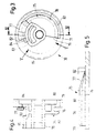
- a pawl 50 is guided thereon perpendicularly to the adjustment direction of the slide, which is indicated by the double arrow A in FIG. 1, and perpendicular to the cover 22 of the housing 20.
- the pawl 50 engages with two lateral strips 51 in two grooves 52 of the slide 40, which are formed by two inverted L-shaped strips 53 placed in one piece on the slide.
- the pawl has a blind bore 54 in the guide direction, which opens into a longitudinal slot 55 toward the slide 40.
- the width of the slot is less than the diameter of the blind bore 54, so that a compression spring 56 inserted into the blind bore 54 cannot fall out of the blind bore 54 through the slot.
- the helical compression spring is supported on the bottom of the blind bore 54 and on an abutment 57 of the slide 40, which engages through the longitudinal slot 55 into the blind bore 54.
- a first end position is indicated by solid lines and a second end position of the pawl 50 by dashed lines. It can be seen that the abutment 57 is covered in every position of the pawl 50 by the wall 58 opposite the longitudinal slot 55, so that the helical compression spring 56 is securely supported on the abutment 57 in the predetermined position.
- the grooves 52 of the slide 40 are open on both sides and the strips 51 of the pawl 50 are the same throughout, so that the pawl can be easily pushed in the direction of the support surface of the helical compression spring 56 on the abutment 57 into the second slide 40.
- the helical compression spring extends the head 59 of the pawl 50 so far can push in until the pawl strikes with a step on the side of the boom 35 facing away from the cover 22.
- the dimensions of the opening 48 and the head 59 of the pawl 50 are coordinated with one another in such a way that there is only a slight play between them.
- the slide 30 and 40 are coupled to each other in both directions of movement. From the abutting of the two approaches 32 and 46 also shows that from the end position of the two slides shown in Figure 1, which corresponds to a locked door lock, the slider 30, the slider 40 with the approach 32 regardless of the pawl 50 in the end position can take, which corresponds to an unlocked door. It does not matter whether the slide 30 is adjusted manually via the locking cylinder or by the electric motor 23. When the door locks are locked, i.e. when the slide 30 is adjusted from the second end position into the end position shown in FIG. 1, the second slide 40 is carried along by the first slide 30 via the pawl 50, again it does not matter whether the first slide 30 is adjusted by hand or by the electric motor.
- the pawl 50 engages in the opening 58, it is also possible to unlock or lock a motor vehicle door with the interior locking handle. If the door is locked and the inner locking handle is now actuated, the second slide 40 and the pawl 50 take the first slide 30 over the drive plate, not shown, which is located in the groove 49 of the extension 46 of the second slide 40 transfers the movement to the door lock. During a locking process, the slide 40 takes the first slide 30 with it via the shoulder 46 or the pawl 50.
- the pawl 50 already described is present, which can be withdrawn from the opening 58 of the slide 30 by a second electric motor 65, provided that the two slides 30 and 40 are in the locking position and the electric motor 65 is live is placed.
- the electric motor 65 similarly to the electric motor 23, finally drives a gearwheel 70 via a worm 67 seated on its shaft 66, via a worm wheel 68 and via a pinion 69 formed in one piece with this worm wheel, which gearwheel just below the arm 35 of the slide 30
- Gear ring 71 is provided and, seen from the boom 35, has a control cam 75 beyond the gear ring 71, which is located at a distance from the gear ring 71 on the side of a radial flange 76 of the gear wheel 10 facing away from this gear ring.
- the control curve 75 extends over an angle of approximately 205 ° and consists of a ramp 77 rising from the underside of the ring gear 71, which extends over an angle of approximately 60 °, and a plateau section 78 adjoining the ramp, the length of which is approximately Is 245 °. At the end 79 of the plateau section, the control curve abruptly breaks off.
- the flange 76 carrying the control cam 75 is cut away from the ring gear 11 against the ring gear 71 by a circumferential groove 80 which is open radially outwards.
- the groove 80 is wider than a cam follower 81, which is formed in one piece with the pawl 50 and protrudes from the pawl 50 perpendicular to its guide direction towards the control cam 75 and, as can be seen from FIG. 2, when the pawl 50 is snapped into the slide 30 is located just below the ring gear 71 at the level of the groove 80.
- the groove 80 also continues below the ramp 77, but there initially decreases continuously in width in accordance with the inclination of the ramp, then again has a section with a constant width because the ramp 77 becomes thinner and finally decreases in it Spread close to zero. That the ramp 71 is thinner at its base than at a distance from it technical reasons.
- the ramp is not only separated radially on the outside, but also at its base 82 from the remaining material of the gearwheel 70.
- the distance between the foot 82 of the ramp 77 and the remaining material of the gearwheel 70 may only be small. This small distance must be created with a section of the mold that is only very thin and therefore prone to breakage. Because the ramp is thinner at its base than at a distance from it, the length of this tool section in the circumferential direction is small and thus the risk of breakage is reduced.
- the ramp 77 is also separated radially on the inside from the rest of the material of the gear 70 by a cutout 83, which can be demolded through an opening 84 in the ring gear 71 of the gear 70.
- the free cut 83 viewed in the circumferential direction, begins at a distance in front of the foot 82 of the ramp 77 and ends shortly after the transition between the ramp 77 and the plateau section 78 within the plateau section 78. Only at this Transition, the ramp 77 is connected to the rest of the material of the gear 70. It can therefore spring away well from the ring gear 71.
- the gearwheel 70 also carries a radial cam 85 with which a limit switch 86 for the electric motor 65 accommodated in the housing 20 can be actuated.
- the switch 86 is a changeover contact, which is controlled by the cam 85 in such a way that the electric motor 65, which always runs in the same direction of rotation, is switched off each time the gear 70 is rotated by approximately 180 °.
- the position of the cam 85 and the position of the control cam 75 are coordinated with one another in such a way that the cam follower 81 of the pawl 50 is in one resting position of the gear 70 shortly before the ramp 77 and in the other resting position of the gear 70 shortly before the end 79 of the plateau section 78 is provided that the sliders 30 and 40 are in the locking position.
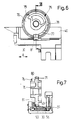
- FIGS. 6 and 7 show the slides 30 and 40 in the locking position, from which they are moved by a movement to the right (in 6) can be brought into the unlocking position.
- the pawl 50 engages with the head 59 in the first slide 30.
- the slide 40 takes the slide 30 into the unlocking position via the pawl 50, so that the lock is unlocked. So the theft protection was not set. If the lock and the anti-theft device are to be set, a signal is given by a longer actuation of the locking cylinder, by a further actuation of the locking cylinder or by actuation of the locking cylinder beyond a certain distance, on the basis of which the second electric motor 65 is energized, when the slider 30 is in the locking position.
- the electric motor 65 rotates the gear 70, viewed in the view according to FIG. 6, clockwise by 180 ° until it is switched off by the switch 86.
- the control curve 75 moves with the ramp 77 under the curve follower 81 of the pawl 50 and pulls it out of the opening 58 of the slide 30, the path of the pawl 50 being determined by the height of the plateau section 78 of the control curve 75.
- the cam follower 81 of the pawl 50 is close to the end 79 of the plateau section 78, while it stood just before the ramp 77 before the gear 70 was rotated 180 °. If, starting from the state according to FIGS. 8 and 9, an interior locking handle of the vehicle is actuated, only the slide 40 is moved to the right into the unlocking position. The position of the slide 30, however, does not change, so that the door lock remains locked.
- the pawl 50 can easily be moved tangentially away from the plateau section 78 of the control cam 75.
- the curve follower 81 has left the plateau section 78, the pawl is supported on a wall of the slide 30 so that it essentially maintains its height with respect to the control curve 75, and slides along the slide 30 with the slide 40. If the inner locking handle is moved back again, the slide 40 also moves back into the position shown in FIG. 8, the cam follower 81 again reaching the plateau section 78 of the control cam 75.
- this is provided with a bevel 87 radially on the outside, as shown in particular in FIG.
- the gearwheel 70 can then be in the rest position according to FIG. 6 or in the rest position according to FIG. 8, but also in any intermediate position. It should always be possible to move the two sliders 30 and 40 from their unlocked position into the locked position in order to at least lock the door of the vehicle, even if it cannot be secured against theft. Above all, the path for the curve follower 81 of the pawl must be free. If the gear wheel is in the position according to FIG. 6, which corresponds to the anti-theft device not set, the pawl 50 can be moved freely, so that locking is possible. This also applies if the circumferential section of the gearwheel 70 not carrying a cam is in the path of the curve follower 81.
- the direction of rotation of the gearwheel 70 when the cam follower 81 runs onto the ramp 77 is selected such that a force component occurring during the run-up acts in the direction of movement of the sliders 30 and 40 in the locking direction. Since the slider abuts a stop in this direction, this force cannot influence the position of the slider.
- This direction of rotation also means that if the power supply fails, the ramp 77 can be passed underneath and the curve follower 81 does not run onto the ramp if it should happen to be in the area of the curve follower. It can thus be achieved that the anti-theft device is in no case set if the power supply for the electric motor 65 fails via the internal locking handle.
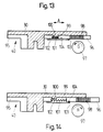
- a first slide 30 and a second slide 40 are again present.
- the second slide consists of two parts 95 and 96, which are at a distance from one another in the direction of movement of the slide, which is again indicated by the double arrow A.
- the part 96 may be referred to as a driver, since it can be moved relative to the part 95 in the direction of arrow A by an electric motor 97 when the part 95 of the slide 40 is at rest relative to the slide 30.
- the driver 96 is provided with a rack section 98, in which a pinion of the electric motor 97, not shown, engages.
- a recess 99 is formed, in which the slide 30 engages with a projection 100.
- the two parts 95 and 96 of the slide 40 are pulled towards one another by a coil spring 101.
- a detent spring 102 is attached to the part 95 of the slide 40, which engages over the driver 96 and can engage with a grid 103 in a latching receptacle 104 of the driver 96.
- the locking is released with a certain force in the direction of movement of the slide, so that the locking spring, grid and locking receptacle can be referred to as a limit force lock.
- the slide 30 can also be guided on a housing in the case of the one according to FIGS. 13 and 14, while the parts 95 and 96 of the slide 40 may be guided independently on the slide 30.
- the electric motor 97 is a reversible motor which can be driven to lock and set the anti-theft device in one direction and to reset the anti-theft device and unlock it in the other direction.
- the slides 30 and 40 may be in their locking position. If the motor is now in the direction of the Arrow G switched on, he pushes the driver 96, in the view according to Figure 13, to the left. The driver 96 takes the slide 30 with it via the projection 100, so that the lock is unlocked. When locking, the electric motor 97 rotates in the other direction H, the other part 95 and the slider 30 being carried along by the part 96 of the slide 40 via the helical spring 101 until they assume the locking position. If the electric motor continues to rotate in the same direction, only the driver 96 is adjusted while increasing the tension of the spring 101 until the grid 103 engages in the snap-in receptacle 104.
- the limit force solution of this latching is selected so that the tensioned spring 101 alone cannot release the latching.
- the parts therefore remain in the position shown in FIG. 14, in which the recess 99 is significantly larger than the projection 100. If an internal locking handle, which is connected to part 95 of slide 40, is actuated, parts 95 and 96 of slide 40 are moved to the left, but slide 30 remains at rest. It is not possible to unlock the lock.
Landscapes
- Lock And Its Accessories (AREA)
- Power-Operated Mechanisms For Wings (AREA)
Applications Claiming Priority (3)
| Application Number | Priority Date | Filing Date | Title |
|---|---|---|---|
| DE4125448 | 1991-08-01 | ||
| DE4125448A DE4125448C2 (de) | 1991-08-01 | 1991-08-01 | Elektromotorischer Stellantrieb für eine zentrale Türverriegelungsanlage eines Kraftfahrzeugs |
| PCT/EP1992/001719 WO1993003245A1 (de) | 1991-08-01 | 1992-07-29 | Elektromotorischer stellantrieb für eine zentrale türverriegelungsanlage eines kraftfahrzeugs |
Publications (2)
| Publication Number | Publication Date |
|---|---|
| EP0551491A1 EP0551491A1 (de) | 1993-07-21 |
| EP0551491B1 true EP0551491B1 (de) | 1995-10-04 |
Family
ID=6437456
Family Applications (1)
| Application Number | Title | Priority Date | Filing Date |
|---|---|---|---|
| EP92916936A Expired - Lifetime EP0551491B1 (de) | 1991-08-01 | 1992-07-29 | Elektromotorischer stellantrieb für eine zentrale türverriegelungsanlage eines kraftfahrzeugs |
Country Status (7)
| Country | Link |
|---|---|
| US (1) | US5453671A (it) |
| EP (1) | EP0551491B1 (it) |
| JP (1) | JPH06502234A (it) |
| BR (1) | BR9205361A (it) |
| DE (1) | DE4125448C2 (it) |
| ES (1) | ES2078058T3 (it) |
| WO (1) | WO1993003245A1 (it) |
Families Citing this family (12)
| Publication number | Priority date | Publication date | Assignee | Title |
|---|---|---|---|---|
| DE4439479A1 (de) * | 1994-11-08 | 1996-05-09 | Bocklenberg & Motte Bomoro | Kraftfahrzeug-Türverschluß mit Zentralverriegelungsantrieb |
| GB2306552B (en) * | 1995-10-25 | 1999-11-17 | Rockwell Lvs | Vehicle door lock actuator |
| US5715713A (en) * | 1996-01-11 | 1998-02-10 | General Motors Corporation | Door latch locking actuator assembly |
| DE19611535A1 (de) * | 1996-03-23 | 1997-09-25 | Bosch Gmbh Robert | Vorrichtung und Verfahren zur elektronischen Überwachung eines in einem Fahrzeug angeordneten Verstellantriebs |
| WO1998033998A1 (en) | 1997-02-04 | 1998-08-06 | Atoma International Corp. | Vehicle door locking system with separate power operated inner door and outer door locking mechanisms |
| DE19958288A1 (de) * | 1999-12-03 | 2001-06-13 | Bosch Gmbh Robert | Elektromotorischer Stellantrieb für ein Kraftfahrzeugschloss |
| DE50014907D1 (de) | 1999-12-31 | 2008-02-21 | Brose Schliesssysteme Gmbh | Elektromotorischer Stellantrieb für ein Kraftfahrzeugschloss |
| GB0019017D0 (en) * | 2000-08-04 | 2000-09-27 | Meritor Light Vehicle Sys Ltd | Actuator |
| JP4511930B2 (ja) * | 2002-08-20 | 2010-07-28 | マグナ クロージャーズ インコーポレイテッド | ドアラッチ用アクチュエータ |
| DE202010013611U1 (de) * | 2010-09-27 | 2011-12-28 | BROSE SCHLIEßSYSTEME GMBH & CO. KG | Kraftfahrzeugschloss |
| DE202011003497U1 (de) * | 2011-03-04 | 2012-06-05 | Kiekert Ag | Kraftfahrzeugtürschloss |
| DE102019109488A1 (de) * | 2019-04-10 | 2020-10-15 | Kiekert Aktiengesellschaft | SCHLIEßSYSTEM FÜR EIN KRAFTFAHRZEUG |
Family Cites Families (20)
| Publication number | Priority date | Publication date | Assignee | Title |
|---|---|---|---|---|
| IT1131405B (it) * | 1979-03-24 | 1986-06-25 | Kiekert Soehne Arn | Dispositivo di chiusura a comando centralizzato per porte di veicoli a motore |
| US4440006A (en) * | 1979-03-24 | 1984-04-03 | Kiekert Gmbh & Co. Kommanditgesellschaft | Antitheft central lock system for a motor vehicle |
| DE3120000A1 (de) * | 1981-05-20 | 1982-12-16 | Robert Bosch Gmbh, 7000 Stuttgart | "antrieb zum verstellen eines gliedes, insbesondere eines zu einem kraftahrzeug gehoerenden riegelelements" |
| DE3210924A1 (de) * | 1982-03-25 | 1983-09-29 | Fichtel & Sachs Ag, 8720 Schweinfurt | Sperreinrichtung fuer das stellorgan eines stellelementes, insbesondere fuer zentral-verriegelungs-einrichtung an kraftfahrzeugen |
| DE3627893A1 (de) * | 1986-08-16 | 1988-02-18 | Swf Auto Electric Gmbh | Stelleinrichtung, insbesondere zur tuerverriegelung bei kraftfahrzeugen |
| DE3629557A1 (de) * | 1986-08-30 | 1988-03-03 | Vdo Schindling | Elektromotorisches stellelement |
| DE3629558A1 (de) * | 1986-08-30 | 1988-03-03 | Vdo Schindling | Elektromotorisches stellelement |
| DE3716507A1 (de) * | 1987-03-07 | 1988-09-15 | Vdo Schindling | Vorrichtung zum betaetigen einer zwei endlagen aufweisenden verriegelungseinrichtung an einem kraftfahrzeug-tuerschloss ueber ein hebelelement |
| JP2512880B2 (ja) * | 1987-04-03 | 1996-07-03 | 株式会社ニコン | 第3電極層から電極取出しを行なつたec素子 |
| FR2614643B1 (fr) * | 1987-04-29 | 1989-07-28 | Rockwell Cim | Ensemble de serrure de porte et d'un dispositif de condamnation anti-vol et anti-agression de cette serrure et serrure faisant partie de cet ensemble |
| JPH0735708B2 (ja) * | 1987-11-30 | 1995-04-19 | 株式会社大井製作所 | 自動車用ドアロック装置 |
| DE3806326C1 (it) * | 1988-02-27 | 1989-01-26 | Daimler-Benz Ag, 7000 Stuttgart, De | |
| GB2217380B (en) * | 1988-04-16 | 1992-03-04 | Rockwell Automotive Body Co | Vehicle door lock actuator. |
| FR2631368B1 (fr) * | 1988-05-11 | 1990-08-24 | Rockwell Cim | Actionneur de condamnation pour serrure, notamment de porte de vehicule automobile |
| US4926337A (en) * | 1988-07-13 | 1990-05-15 | Bryant Grinder Corporation | Automatic workpart centering mechanism for a chuck |
| DE8915994U1 (it) * | 1988-08-13 | 1992-11-05 | Kiekert Gmbh & Co Kg, 5628 Heiligenhaus, De | |
| GB8827125D0 (en) * | 1988-11-21 | 1988-12-29 | Capital Marketing Ltd | Door locking systems for motor vehicles |
| DE3938680A1 (de) * | 1989-07-22 | 1991-01-31 | Kiekert Gmbh Co Kg | Kraftfahrzeugtuerverschluss mit aufgesetzter zentralverriegelungseinrichtung |
| DE4015522A1 (de) * | 1989-09-14 | 1991-03-28 | Bosch Gmbh Robert | Vorrichtung zum sperren und entsperren von geschlossenen tueren zum innenraum eines kraftfahrzeuges |
| FR2656026B1 (fr) * | 1989-12-15 | 1993-04-16 | Vachette Sa | Dispositif de commande electrique d'un levier pivotant maintenu libre aux deux extremites de sa course et serrure comportant ce dispositif. |
-
1991
- 1991-08-01 DE DE4125448A patent/DE4125448C2/de not_active Expired - Fee Related
-
1992
- 1992-07-29 WO PCT/EP1992/001719 patent/WO1993003245A1/de active IP Right Grant
- 1992-07-29 BR BR9205361A patent/BR9205361A/pt not_active IP Right Cessation
- 1992-07-29 EP EP92916936A patent/EP0551491B1/de not_active Expired - Lifetime
- 1992-07-29 ES ES92916936T patent/ES2078058T3/es not_active Expired - Lifetime
- 1992-07-29 US US07/039,005 patent/US5453671A/en not_active Expired - Lifetime
- 1992-07-29 JP JP5503251A patent/JPH06502234A/ja active Pending
Also Published As
| Publication number | Publication date |
|---|---|
| DE4125448A1 (de) | 1993-02-04 |
| WO1993003245A1 (de) | 1993-02-18 |
| JPH06502234A (ja) | 1994-03-10 |
| DE4125448C2 (de) | 2003-11-06 |
| ES2078058T3 (es) | 1995-12-01 |
| US5453671A (en) | 1995-09-26 |
| BR9205361A (pt) | 1993-11-16 |
| EP0551491A1 (de) | 1993-07-21 |
Similar Documents
| Publication | Publication Date | Title |
|---|---|---|
| DE69503354T3 (de) | Betätigungsvorrichtung für kraftfahrzeugtürschlösse | |
| EP1317596B1 (de) | Kraftfahrzeug-türschloss mit kombiniertem zentralverriegelungs- und öffnungsantrieb | |
| DE102006024685B4 (de) | Elektromechanisches, durch Drücken verschließbares Schloss | |
| DE3844849C2 (de) | Treibstangenverschluß | |
| EP0551491B1 (de) | Elektromotorischer stellantrieb für eine zentrale türverriegelungsanlage eines kraftfahrzeugs | |
| DE3031066A1 (de) | Zentralgesteuerte verschlusseinrichtung fuer kraftfahrzeugtueren | |
| EP0942135B2 (de) | Verriegelungseinrichtung | |
| DE102004011798B3 (de) | Schloss, insbesondere für Fahrzeugtüren, -klappen oder dergleichen | |
| DE3247018C2 (it) | ||
| DE102004014550A1 (de) | Kraftfahrzeugschloß | |
| DE4014041A1 (de) | Schliesszylinderbetaetigbares treibstangenschloss | |
| DE19534609C2 (de) | Selbstverriegelndes Motorschloss | |
| EP0454966B1 (de) | Schliesszylinderbetätigbares Treibstangenschloss | |
| DE19627246B4 (de) | Kraftfahrzeugtürverschluß, der für die Funktionsstellung "entriegelt", "verriegelt" und "zusatzgesichert" eingerichtet ist | |
| EP1355022B1 (de) | Vorrichtung zum Betätigen eines Verschlusses von Türen, Klappen od. dgl., insbesondere an Fahrzeugen | |
| DE102005000078A1 (de) | Schloss | |
| DE102015000606A1 (de) | Verriegelungsvorrichtung für einen schwenkbar gelagerten Flügel | |
| DE102007025723B3 (de) | Kupplungseinheit für ein Garagentor, insbesondere Kipp-, Schwenk- oder Sektionaltor | |
| DE10308243B4 (de) | Schließanlage, insbesondere Türverschluss, Fensterverschluss oder dergleichen | |
| EP0381820B1 (de) | Treibstangenverschluss | |
| EP0853176A1 (de) | Türöffner | |
| DE3121850A1 (de) | "riegelverschluss fuer tueren, klappen oder dergleichen von nutzfahrzeugen" | |
| DE10142134A1 (de) | Stellantrieb | |
| EP0581338A2 (de) | Schliesszylinderbetätigbares Treibstangenschloss | |
| DE3825909C2 (it) |
Legal Events
| Date | Code | Title | Description |
|---|---|---|---|
| PUAI | Public reference made under article 153(3) epc to a published international application that has entered the european phase |
Free format text: ORIGINAL CODE: 0009012 |
|
| 17P | Request for examination filed |
Effective date: 19930320 |
|
| AK | Designated contracting states |
Kind code of ref document: A1 Designated state(s): ES FR GB IT SE |
|
| RAP1 | Party data changed (applicant data changed or rights of an application transferred) |
Owner name: ITT AUTOMOTIVE EUROPE GMBH |
|
| 17Q | First examination report despatched |
Effective date: 19941129 |
|
| ITF | It: translation for a ep patent filed |
Owner name: DE DOMINICIS & MAYER S.R.L. |
|
| GRAA | (expected) grant |
Free format text: ORIGINAL CODE: 0009210 |
|
| AK | Designated contracting states |
Kind code of ref document: B1 Designated state(s): ES FR GB IT SE |
|
| GBT | Gb: translation of ep patent filed (gb section 77(6)(a)/1977) |
Effective date: 19951023 |
|
| REG | Reference to a national code |
Ref country code: ES Ref legal event code: FG2A Ref document number: 2078058 Country of ref document: ES Kind code of ref document: T3 |
|
| ET | Fr: translation filed | ||
| PLBE | No opposition filed within time limit |
Free format text: ORIGINAL CODE: 0009261 |
|
| STAA | Information on the status of an ep patent application or granted ep patent |
Free format text: STATUS: NO OPPOSITION FILED WITHIN TIME LIMIT |
|
| 26N | No opposition filed | ||
| REG | Reference to a national code |
Ref country code: GB Ref legal event code: IF02 |
|
| PGFP | Annual fee paid to national office [announced via postgrant information from national office to epo] |
Ref country code: SE Payment date: 20060619 Year of fee payment: 15 |
|
| PGFP | Annual fee paid to national office [announced via postgrant information from national office to epo] |
Ref country code: ES Payment date: 20060717 Year of fee payment: 15 |
|
| PGFP | Annual fee paid to national office [announced via postgrant information from national office to epo] |
Ref country code: GB Payment date: 20060719 Year of fee payment: 15 |
|
| PGFP | Annual fee paid to national office [announced via postgrant information from national office to epo] |
Ref country code: IT Payment date: 20060731 Year of fee payment: 15 Ref country code: FR Payment date: 20060731 Year of fee payment: 15 |
|
| EUG | Se: european patent has lapsed | ||
| GBPC | Gb: european patent ceased through non-payment of renewal fee |
Effective date: 20070729 |
|
| PG25 | Lapsed in a contracting state [announced via postgrant information from national office to epo] |
Ref country code: SE Free format text: LAPSE BECAUSE OF NON-PAYMENT OF DUE FEES Effective date: 20070730 |
|
| PG25 | Lapsed in a contracting state [announced via postgrant information from national office to epo] |
Ref country code: GB Free format text: LAPSE BECAUSE OF NON-PAYMENT OF DUE FEES Effective date: 20070729 |
|
| REG | Reference to a national code |
Ref country code: FR Ref legal event code: ST Effective date: 20080331 |
|
| PG25 | Lapsed in a contracting state [announced via postgrant information from national office to epo] |
Ref country code: FR Free format text: LAPSE BECAUSE OF NON-PAYMENT OF DUE FEES Effective date: 20070731 |
|
| REG | Reference to a national code |
Ref country code: ES Ref legal event code: FD2A Effective date: 20070730 |
|
| PG25 | Lapsed in a contracting state [announced via postgrant information from national office to epo] |
Ref country code: ES Free format text: LAPSE BECAUSE OF NON-PAYMENT OF DUE FEES Effective date: 20070730 |
|
| PG25 | Lapsed in a contracting state [announced via postgrant information from national office to epo] |
Ref country code: IT Free format text: LAPSE BECAUSE OF NON-PAYMENT OF DUE FEES Effective date: 20070729 |