EP0551491B1 - Electromotor actuator for the central door locking system of a motor vehicle - Google Patents
Electromotor actuator for the central door locking system of a motor vehicle Download PDFInfo
- Publication number
- EP0551491B1 EP0551491B1 EP92916936A EP92916936A EP0551491B1 EP 0551491 B1 EP0551491 B1 EP 0551491B1 EP 92916936 A EP92916936 A EP 92916936A EP 92916936 A EP92916936 A EP 92916936A EP 0551491 B1 EP0551491 B1 EP 0551491B1
- Authority
- EP
- European Patent Office
- Prior art keywords
- slide
- actuator according
- electromotive actuator
- electric motor
- latch
- Prior art date
- Legal status (The legal status is an assumption and is not a legal conclusion. Google has not performed a legal analysis and makes no representation as to the accuracy of the status listed.)
- Expired - Lifetime
Links
Images


Classifications
-
- E—FIXED CONSTRUCTIONS
- E05—LOCKS; KEYS; WINDOW OR DOOR FITTINGS; SAFES
- E05B—LOCKS; ACCESSORIES THEREFOR; HANDCUFFS
- E05B81/00—Power-actuated vehicle locks
- E05B81/24—Power-actuated vehicle locks characterised by constructional features of the actuator or the power transmission
- E05B81/25—Actuators mounted separately from the lock and controlling the lock functions through mechanical connections
-
- E—FIXED CONSTRUCTIONS
- E05—LOCKS; KEYS; WINDOW OR DOOR FITTINGS; SAFES
- E05B—LOCKS; ACCESSORIES THEREFOR; HANDCUFFS
- E05B85/00—Details of vehicle locks not provided for in groups E05B77/00 - E05B83/00
- E05B85/02—Lock casings
-
- Y—GENERAL TAGGING OF NEW TECHNOLOGICAL DEVELOPMENTS; GENERAL TAGGING OF CROSS-SECTIONAL TECHNOLOGIES SPANNING OVER SEVERAL SECTIONS OF THE IPC; TECHNICAL SUBJECTS COVERED BY FORMER USPC CROSS-REFERENCE ART COLLECTIONS [XRACs] AND DIGESTS
- Y10—TECHNICAL SUBJECTS COVERED BY FORMER USPC
- Y10S—TECHNICAL SUBJECTS COVERED BY FORMER USPC CROSS-REFERENCE ART COLLECTIONS [XRACs] AND DIGESTS
- Y10S292/00—Closure fasteners
- Y10S292/03—Automobile multiple door latches
-
- Y—GENERAL TAGGING OF NEW TECHNOLOGICAL DEVELOPMENTS; GENERAL TAGGING OF CROSS-SECTIONAL TECHNOLOGIES SPANNING OVER SEVERAL SECTIONS OF THE IPC; TECHNICAL SUBJECTS COVERED BY FORMER USPC CROSS-REFERENCE ART COLLECTIONS [XRACs] AND DIGESTS
- Y10—TECHNICAL SUBJECTS COVERED BY FORMER USPC
- Y10S—TECHNICAL SUBJECTS COVERED BY FORMER USPC CROSS-REFERENCE ART COLLECTIONS [XRACs] AND DIGESTS
- Y10S292/00—Closure fasteners
- Y10S292/23—Vehicle door latches
-
- Y—GENERAL TAGGING OF NEW TECHNOLOGICAL DEVELOPMENTS; GENERAL TAGGING OF CROSS-SECTIONAL TECHNOLOGIES SPANNING OVER SEVERAL SECTIONS OF THE IPC; TECHNICAL SUBJECTS COVERED BY FORMER USPC CROSS-REFERENCE ART COLLECTIONS [XRACs] AND DIGESTS
- Y10—TECHNICAL SUBJECTS COVERED BY FORMER USPC
- Y10T—TECHNICAL SUBJECTS COVERED BY FORMER US CLASSIFICATION
- Y10T292/00—Closure fasteners
- Y10T292/08—Bolts
- Y10T292/096—Sliding
- Y10T292/1014—Operating means
- Y10T292/1021—Motor
-
- Y—GENERAL TAGGING OF NEW TECHNOLOGICAL DEVELOPMENTS; GENERAL TAGGING OF CROSS-SECTIONAL TECHNOLOGIES SPANNING OVER SEVERAL SECTIONS OF THE IPC; TECHNICAL SUBJECTS COVERED BY FORMER USPC CROSS-REFERENCE ART COLLECTIONS [XRACs] AND DIGESTS
- Y10—TECHNICAL SUBJECTS COVERED BY FORMER USPC
- Y10T—TECHNICAL SUBJECTS COVERED BY FORMER US CLASSIFICATION
- Y10T70/00—Locks
- Y10T70/50—Special application
- Y10T70/5889—For automotive vehicles
-
- Y—GENERAL TAGGING OF NEW TECHNOLOGICAL DEVELOPMENTS; GENERAL TAGGING OF CROSS-SECTIONAL TECHNOLOGIES SPANNING OVER SEVERAL SECTIONS OF THE IPC; TECHNICAL SUBJECTS COVERED BY FORMER USPC CROSS-REFERENCE ART COLLECTIONS [XRACs] AND DIGESTS
- Y10—TECHNICAL SUBJECTS COVERED BY FORMER USPC
- Y10T—TECHNICAL SUBJECTS COVERED BY FORMER US CLASSIFICATION
- Y10T70/00—Locks
- Y10T70/60—Systems
- Y10T70/625—Operation and control
- Y10T70/65—Central control
-
- Y—GENERAL TAGGING OF NEW TECHNOLOGICAL DEVELOPMENTS; GENERAL TAGGING OF CROSS-SECTIONAL TECHNOLOGIES SPANNING OVER SEVERAL SECTIONS OF THE IPC; TECHNICAL SUBJECTS COVERED BY FORMER USPC CROSS-REFERENCE ART COLLECTIONS [XRACs] AND DIGESTS
- Y10—TECHNICAL SUBJECTS COVERED BY FORMER USPC
- Y10T—TECHNICAL SUBJECTS COVERED BY FORMER US CLASSIFICATION
- Y10T70/00—Locks
- Y10T70/70—Operating mechanism
- Y10T70/7051—Using a powered device [e.g., motor]
- Y10T70/7062—Electrical type [e.g., solenoid]
- Y10T70/7113—Projected and retracted electrically
Definitions
- the invention relates to an electromotive actuator for a central door locking system of a motor vehicle, which actuator has the features from the preamble of claim 1.
- An electromotive actuator which has all the features from the preamble of claim 1 including the feature mentioned as being particularly advantageous, is known from DE-OS 36 27 893.
- This actuator has a z. B. from DE-OS 32 10 923 known electromotive actuator the advantage that the slide can also be easily adjusted manually from the end positions.
- the electric motor and the gears of the transmission connected downstream must be rotated when the slide is manually adjusted.
- the actuator shown in DE-OS 32 10 923 for a central door locking system of a motor vehicle not only allows central locking or unlocking of a motor vehicle door, but also a so-called anti-theft device.
- a central door locking system for a motor vehicle that is equipped with an anti-theft device a door lock can be locked and unlocked from the outside. This is also basically possible with a handle inside the motor vehicle. However, if the anti-theft device is set from the outside, it is no longer possible to unlock the door lock with the handle on the inside.
- the anti-theft device is realized in that the slide is locked against movement in the sense of unlocking by a pawl which can be pivoted by a second electric motor.
- This has various disadvantages. In the event of a break-in and an actuation of the handle inside the motor vehicle, parts within the actuator are exposed to high forces which can be exerted on them via the handle. If you do not want to accept damage, the parts must be designed accordingly strong.
- Another disadvantage is that a vehicle door can no longer be unlocked if the motor actuating the pawl fails for some reason in the anti-theft position.
- the invention has for its object to provide an electromotive actuator for a central door locking system of a motor vehicle, in which actuator an anti-theft device is provided without parts of the actuator being excessively loaded during an attempted break-in, and in which actuator manual unlocking from the outside is also then is possible if the anti-theft device cannot be reset by a motor.
- an electromotive actuator which, in addition to the features from the preamble, is also equipped with the features from the characterizing part of claim 1.
- a second slide is initially provided, which at least for unlocking the door lock with the handle inside the motor vehicle can be coupled.
- the second slide can be coupled to the first slide via a pawl which is guided on one of the two slides so as to be adjustable transversely to the direction of movement of the slide and which engages in the other slide under the action of a spring element.
- the two slides can be regarded as a single slider for the movement sequence, so that unlocking is readily possible from inside the motor vehicle.
- the pawl can be retracted by a second electric motor via a control element from the engagement in the other slide against the action of the spring element. This means that it is no longer possible to transmit motion from the second to the first slide, so that if the second slide is attempted to break in, whether the latch is now guided on it or on the first slide, the door lock cannot be unlocked.
- the forces introduced into the handle inside the motor vehicle do not have to be absorbed by parts of the actuator, since the second slide can be moved.
- the first slider regardless of whether the pawl is guided on it or not, can still lock in from the outside or from the first electric motor the unlocking position are brought.
- this also means that when unlocking the door lock from the anti-theft position of the pawl, a special sequence in the operation of the pawl and the displacement of the first slide need not be observed.
- the electromotive actuator according to claim 2 also provides a solution to the problem.
- This actuator also has a first slide, which can be connected in a direction-independent manner to a door lock of the motor vehicle, and a second slide, which can be coupled for unlocking with a handle inside a motor vehicle is. Both slides engage with a projection and a recess transversely to their direction of movement, a driver of one of the two sliders being movable relative to the slider in the direction of movement of the two slides to prevent theft of an electric motor to form a dead gear by reducing the projection or increasing the recess is. After the dead gear has been formed, the second slide can be opened again move freely from the handle inside the motor vehicle without taking the first slide with it and thus unlocking the door lock.
- An advantageous embodiment of an actuator according to claim 1 or 2 is contained in claim 3. Thereafter, a smooth manual adjustment of the first slide is possible without having to move the first electric motor and a gear arranged after it.
- the second slide can be taken from the first slide in the direction of unlocking independently of the pawl.
- the second slide can be taken along with the first slide from the outside without the anti-theft device having been reset by the second electric motor beforehand.
- the control member is a control cam with a ramp. From the basic mode of operation, it is unimportant whether the direction of movement of the ramp on the latch when it is retracted, that is to say when the anti-theft device is set, corresponds to the direction of the slide when locking or unlocking. However, it appears to be more advantageous if the ramp moves according to claim 7 when the pawl runs in such a direction that corresponds to the direction of movement of the slide when locking. A force is then not exerted on the pawl from the ramp in the direction of unlocking of the slides, so that there is no danger that the slides move somewhat out of the locking position and the setting of the anti-theft device is made difficult or not possible at all.
- the ramp of the control cam can happen to be in the path of the pawl, it is provided according to claim 9 that the ramp of the control curve is designed to be resilient in such a way that the pawl when the slide is adjusted from the unlocking position into the locking position under the ramp can be pushed or pushed under the ramp.
- a prerequisite for this spring characteristic of the ramp is, of course, that it is separated from its support at its base. Further advantageous embodiments to maintain the spring property of the ramp are set out in claims 10 and 11.
- the ramp at its foot should be separated from its carrier.
- the distance must not be large to ensure that the pawl runs onto the ramp.
- the foot of the ramp When shaping the control curve, which is usually injection molded with its carrier made of plastic, the foot of the ramp must therefore be separated from the carrier by a tool section which is as thin as possible. So that this thin tool section does not have to be so long, the ramp is thinner at its foot than at a distance from its foot.
- the control cam is preferably located on a gearwheel that can be driven by the second electric motor.
- the precautions against failure of the second electric motor can be implemented most easily when the control cam is arranged in such a way that the pawl can be moved by it in the direction of the axis of the gearwheel.
- the control curve advantageously has a plateau section without a change in height.
- the second electric motor continues to follow an indefinite path which, owing to the plateau section of the control curve, cannot affect the position of the pawl. If the pawl is guided on the second slide, it is brought into the unlocked position together with the second slide in an attempted theft.
- the handle When the handle is reset in the interior of the vehicle, it returns to the locking position with the second slide, again reaching the plateau section of the control curve.
- the plateau section according to claim 17 has on its radially outer edge a sloping slope in the radial direction.
- the gearwheel can also be driven by the electric motor in only one direction of rotation.
- the second electric motor can be switched on by the spring element both for pulling back the pawl and for pushing the pawl forward, the gear wheel then being able to be rotated through approximately 180 ° each time the electric motor is switched on.
- the pawl can be moved away from the control cam even when the anti-theft device is set, it is in principle not necessary for the second electric motor to be switched on to reset the anti-theft device.
- the second electric motor can only be switched on for pulling back the pawl, the gearwheel preferably being rotatable through 360 ° after each switching on of the electric motor.
- the number of switching operations and, if the gearwheel is rotated less than 360 ° in each case, the total operating time of the second electric motor can be reduced.
- only one opener is required as a limit switch, so that the number of electrical lines within the actuator can also be reduced.
- a time delay could, however, also be created in that the motors are switched on at the same time, but the gearwheel with the control cam runs much slower than the gearwheel with the crank adjusting the slide or, in the case that the gearwheel with the control cam, in each case by 360 ° is rotated, the ramp only comes to a pawl after an angle of rotation that is substantially greater than 180 °.
- the latter solutions are not very safe, since the length of time required for the slide to be adjusted by the first electric motor can vary considerably.
- the spring element of a coil spring which is located in a blind bore of the pawl and is supported on an extension of the pawl guiding the slide, which extension through a longitudinal slot in which the blind bore is open to the outside the blind hole protrudes.
- the jack is then very long and can be made correspondingly long.
- the path of the pawl out of its guidance is advantageously limited by a stop of the slide not guiding the pawl. A stop on the slide guiding the pawl is thereby avoided, so that the pawl is easily inserted into the guide can be.
- the coil spring is well supported laterally in each position of the pawl.
- the space available can make it appear favorable that the pawl is guided on the second slide according to claim 28. If, on the other hand, the pawl is guided on the first slide, it is not carried along when the anti-theft device is set and the handle inside the vehicle is actuated, which leads to a movement of the second slide, but remains on the control curve. There is no need to take precautions to ensure that the jack z. B. remains in the anti-theft position by a support surface on the first slide or on the housing or is pushed back into this position when the second slide returns.
- the whole construction of the lock, electromotive actuator and handle inside the vehicle and the mechanical connections between these parts can be chosen so that the second slide can only be actuated via the handle inside the vehicle in the sense of unlocking the door lock. So that a locking via the handle inside is possible, it is provided according to claim 31 that the slide can be coupled via a driver with the handle inside the motor vehicle and that the driver is in the direction of movement of the slide between them. If, on the other hand, the second slide can be actuated via the handle inside the motor vehicle both in terms of locking and in terms of unlocking, the second slide can advantageously be directly positively coupled to the driver in both directions of movement.
- the driver is advantageously movable according to claim 36 against the action of a spring element, which is supported on the associated slide. It also appears favorable if the driver can be coupled in one position to the associated slide by a limit force lock. Basically, this can be done in both operating positions of the driver in relation to the associated slide. When using a spring element, however, coupling by means of a limit force lock is only sufficient in one position, namely in that in which the projection is reduced or the recess is increased. Likewise, without a spring element, a single limit force lock in the named position of the driver is sufficient if an anti-theft device is also provided for each locking.
- An electromotive actuator according to claim 2 is particularly suitable for using only a single reversible electric motor for locking and theft protection, with which the driver is adjustably coupled.
- the coupling of the driver with the electric motor can, for. B. take place via a gear driven by the electric motor and a rack of the driver.
- the direction of rotation of the motor during anti-theft protection advantageously coincides with the direction of rotation during locking and during anti-theft protection advantageously corresponds to the direction of rotation during unlocking.
- a first electric motor 23 is fixed in a two-part housing 20 with a housing pot 21 and a cover 22 made of plastic, which has a worm 25 seated on its shaft 24, a worm wheel 26 and an integral part thereof Worm gear designed but not shown pinion finally drives a crank wheel 21. From this crank wheel 27 projects a conical tapering crank pin 28, which consequently moves on a circular path.
- the axis of the worm wheel 26 is designated 29.
- a slide 30 is guided in a longitudinally movable manner, which can be connected via a U-shaped recesses 31, which are located on a projection 32 protruding from the housing 20, to a push rod, not shown, which can be connected to a Door locking mechanism in a motor vehicle acts.
- a bracket 35 of the slide 30, which extends parallel to the cover 22, namely — in the plan view according to FIG. 1 — on the underside of the bracket 35, two stops 33 and 34 are provided, which interact with the crank pin 28. It can be seen from FIG.
- the distance 8 between the two stops 33 and 34 in the adjustment direction of the slide 30 is very much smaller than the radius of the crank, that is to say very much smaller than the distance of the crank pin 28 from the axis 29 of the crank wheel 27 This allows for a large stroke of the spool 30 for a given crank wheel loss.
- the distance D between the two stops 33 and 34 transversely to the adjustment direction of the slide 30 is only slightly larger than the diameter of the crank pin 28. In the one end position of the crank wheel 27 and the slider 30 shown in FIG. 1, the crank pin 28 is located transversely to the adjustment direction seen the slider 30, between the two stops 33 and 34.
- the slider 30 is thus completely decoupled from the crank pin 28 or the crank wheel 27 and can easily be moved manually from the end position shown into the other end position and with the push rod already mentioned can be switched back again.
- the crank wheel 27, the crank pin 28 and the slide 30 are in the other end position in which the crank wheel is rotated by 180 ° with respect to the position shown in FIG. 1.
- crank pin 28 If, starting from the position shown in FIG. 1, the electric motor 23 driving the crank pin 28 is now switched on, the crank pin is moved clockwise on its circular adjustment path. He then strikes the stop 33 of the slide 30 and takes stop 33 and slide 30 with him into the other end position during the following part of his movement. After a rotation angle of 180 °, the crank pin is stopped again. When the electric motor 23 is switched on again, the crank pin 28 strikes the stop 34 of the slide 30 and returns the slide to the end position shown in FIG. 1, which corresponds to a locked door.
- crank pin 28 is driven by an angle of 180 ° in the same direction of rotation in each setting process.
- the crank pin 28 is coupled to the stops 33 and 34 only during part of its movement, but is decoupled from the slide 30 in the end positions after an angle of rotation of 180 ° in each case.
- the slider 30 is arranged essentially parallel to a side wall of the housing 20 and engages with the thin extension 35 parallel to the cover 22 and just below it in the housing pot 21.
- a second slide 40 is guided therein, the direction of a possible movement of the second slide 40 relative to the first slide 30 coinciding with the direction of the double arrow A.
- the second slide 40 has two strips 41 on the side, which engage in grooves 42 of the first slide 30 which are open at one end for introducing the second slide 40 into the first slide 30.
- one side wall 43 of the grooves 42 is higher than the other side wall.
- the strips 41 on the side facing the side wall 43 are higher than on the other side, so that the slide 40 can only be inserted into the slide 30 in a single relative position thereof.
- the open end of the grooves 42 is located on the end face 44 of the slide 30.
- the two strips 45 of the slide 30, in which the grooves 42 are located, are only in the area of the extension 32 and at the other end of the grooves 42 connected.
- the second slide 40 can therefore reach out between the end face 44 and the extension 32 of the first slide 30 with an extension 46 through the same opening 47 in the side wall 48 of the housing 20, through which the slide 30 with the extension 32 also does so.
- a drive plate not shown, can be used in the shoulder 46 of the second slide 40, which, for. B.
- Driving plate and second slide 40 are thus positively coupled to one another in the direction of the double arrow A.
- the two lugs 32 and 46 lie directly against one another, as shown in FIG. 1.
- a pawl 50 is guided thereon perpendicularly to the adjustment direction of the slide, which is indicated by the double arrow A in FIG. 1, and perpendicular to the cover 22 of the housing 20.
- the pawl 50 engages with two lateral strips 51 in two grooves 52 of the slide 40, which are formed by two inverted L-shaped strips 53 placed in one piece on the slide.
- the pawl has a blind bore 54 in the guide direction, which opens into a longitudinal slot 55 toward the slide 40.
- the width of the slot is less than the diameter of the blind bore 54, so that a compression spring 56 inserted into the blind bore 54 cannot fall out of the blind bore 54 through the slot.
- the helical compression spring is supported on the bottom of the blind bore 54 and on an abutment 57 of the slide 40, which engages through the longitudinal slot 55 into the blind bore 54.
- a first end position is indicated by solid lines and a second end position of the pawl 50 by dashed lines. It can be seen that the abutment 57 is covered in every position of the pawl 50 by the wall 58 opposite the longitudinal slot 55, so that the helical compression spring 56 is securely supported on the abutment 57 in the predetermined position.
- the grooves 52 of the slide 40 are open on both sides and the strips 51 of the pawl 50 are the same throughout, so that the pawl can be easily pushed in the direction of the support surface of the helical compression spring 56 on the abutment 57 into the second slide 40.
- the helical compression spring extends the head 59 of the pawl 50 so far can push in until the pawl strikes with a step on the side of the boom 35 facing away from the cover 22.
- the dimensions of the opening 48 and the head 59 of the pawl 50 are coordinated with one another in such a way that there is only a slight play between them.
- the slide 30 and 40 are coupled to each other in both directions of movement. From the abutting of the two approaches 32 and 46 also shows that from the end position of the two slides shown in Figure 1, which corresponds to a locked door lock, the slider 30, the slider 40 with the approach 32 regardless of the pawl 50 in the end position can take, which corresponds to an unlocked door. It does not matter whether the slide 30 is adjusted manually via the locking cylinder or by the electric motor 23. When the door locks are locked, i.e. when the slide 30 is adjusted from the second end position into the end position shown in FIG. 1, the second slide 40 is carried along by the first slide 30 via the pawl 50, again it does not matter whether the first slide 30 is adjusted by hand or by the electric motor.
- the pawl 50 engages in the opening 58, it is also possible to unlock or lock a motor vehicle door with the interior locking handle. If the door is locked and the inner locking handle is now actuated, the second slide 40 and the pawl 50 take the first slide 30 over the drive plate, not shown, which is located in the groove 49 of the extension 46 of the second slide 40 transfers the movement to the door lock. During a locking process, the slide 40 takes the first slide 30 with it via the shoulder 46 or the pawl 50.
- the pawl 50 already described is present, which can be withdrawn from the opening 58 of the slide 30 by a second electric motor 65, provided that the two slides 30 and 40 are in the locking position and the electric motor 65 is live is placed.
- the electric motor 65 similarly to the electric motor 23, finally drives a gearwheel 70 via a worm 67 seated on its shaft 66, via a worm wheel 68 and via a pinion 69 formed in one piece with this worm wheel, which gearwheel just below the arm 35 of the slide 30
- Gear ring 71 is provided and, seen from the boom 35, has a control cam 75 beyond the gear ring 71, which is located at a distance from the gear ring 71 on the side of a radial flange 76 of the gear wheel 10 facing away from this gear ring.
- the control curve 75 extends over an angle of approximately 205 ° and consists of a ramp 77 rising from the underside of the ring gear 71, which extends over an angle of approximately 60 °, and a plateau section 78 adjoining the ramp, the length of which is approximately Is 245 °. At the end 79 of the plateau section, the control curve abruptly breaks off.
- the flange 76 carrying the control cam 75 is cut away from the ring gear 11 against the ring gear 71 by a circumferential groove 80 which is open radially outwards.
- the groove 80 is wider than a cam follower 81, which is formed in one piece with the pawl 50 and protrudes from the pawl 50 perpendicular to its guide direction towards the control cam 75 and, as can be seen from FIG. 2, when the pawl 50 is snapped into the slide 30 is located just below the ring gear 71 at the level of the groove 80.
- the groove 80 also continues below the ramp 77, but there initially decreases continuously in width in accordance with the inclination of the ramp, then again has a section with a constant width because the ramp 77 becomes thinner and finally decreases in it Spread close to zero. That the ramp 71 is thinner at its base than at a distance from it technical reasons.
- the ramp is not only separated radially on the outside, but also at its base 82 from the remaining material of the gearwheel 70.
- the distance between the foot 82 of the ramp 77 and the remaining material of the gearwheel 70 may only be small. This small distance must be created with a section of the mold that is only very thin and therefore prone to breakage. Because the ramp is thinner at its base than at a distance from it, the length of this tool section in the circumferential direction is small and thus the risk of breakage is reduced.
- the ramp 77 is also separated radially on the inside from the rest of the material of the gear 70 by a cutout 83, which can be demolded through an opening 84 in the ring gear 71 of the gear 70.
- the free cut 83 viewed in the circumferential direction, begins at a distance in front of the foot 82 of the ramp 77 and ends shortly after the transition between the ramp 77 and the plateau section 78 within the plateau section 78. Only at this Transition, the ramp 77 is connected to the rest of the material of the gear 70. It can therefore spring away well from the ring gear 71.
- the gearwheel 70 also carries a radial cam 85 with which a limit switch 86 for the electric motor 65 accommodated in the housing 20 can be actuated.
- the switch 86 is a changeover contact, which is controlled by the cam 85 in such a way that the electric motor 65, which always runs in the same direction of rotation, is switched off each time the gear 70 is rotated by approximately 180 °.
- the position of the cam 85 and the position of the control cam 75 are coordinated with one another in such a way that the cam follower 81 of the pawl 50 is in one resting position of the gear 70 shortly before the ramp 77 and in the other resting position of the gear 70 shortly before the end 79 of the plateau section 78 is provided that the sliders 30 and 40 are in the locking position.
- FIGS. 6 and 7 show the slides 30 and 40 in the locking position, from which they are moved by a movement to the right (in 6) can be brought into the unlocking position.
- the pawl 50 engages with the head 59 in the first slide 30.
- the slide 40 takes the slide 30 into the unlocking position via the pawl 50, so that the lock is unlocked. So the theft protection was not set. If the lock and the anti-theft device are to be set, a signal is given by a longer actuation of the locking cylinder, by a further actuation of the locking cylinder or by actuation of the locking cylinder beyond a certain distance, on the basis of which the second electric motor 65 is energized, when the slider 30 is in the locking position.
- the electric motor 65 rotates the gear 70, viewed in the view according to FIG. 6, clockwise by 180 ° until it is switched off by the switch 86.
- the control curve 75 moves with the ramp 77 under the curve follower 81 of the pawl 50 and pulls it out of the opening 58 of the slide 30, the path of the pawl 50 being determined by the height of the plateau section 78 of the control curve 75.
- the cam follower 81 of the pawl 50 is close to the end 79 of the plateau section 78, while it stood just before the ramp 77 before the gear 70 was rotated 180 °. If, starting from the state according to FIGS. 8 and 9, an interior locking handle of the vehicle is actuated, only the slide 40 is moved to the right into the unlocking position. The position of the slide 30, however, does not change, so that the door lock remains locked.
- the pawl 50 can easily be moved tangentially away from the plateau section 78 of the control cam 75.
- the curve follower 81 has left the plateau section 78, the pawl is supported on a wall of the slide 30 so that it essentially maintains its height with respect to the control curve 75, and slides along the slide 30 with the slide 40. If the inner locking handle is moved back again, the slide 40 also moves back into the position shown in FIG. 8, the cam follower 81 again reaching the plateau section 78 of the control cam 75.
- this is provided with a bevel 87 radially on the outside, as shown in particular in FIG.
- the gearwheel 70 can then be in the rest position according to FIG. 6 or in the rest position according to FIG. 8, but also in any intermediate position. It should always be possible to move the two sliders 30 and 40 from their unlocked position into the locked position in order to at least lock the door of the vehicle, even if it cannot be secured against theft. Above all, the path for the curve follower 81 of the pawl must be free. If the gear wheel is in the position according to FIG. 6, which corresponds to the anti-theft device not set, the pawl 50 can be moved freely, so that locking is possible. This also applies if the circumferential section of the gearwheel 70 not carrying a cam is in the path of the curve follower 81.
- the direction of rotation of the gearwheel 70 when the cam follower 81 runs onto the ramp 77 is selected such that a force component occurring during the run-up acts in the direction of movement of the sliders 30 and 40 in the locking direction. Since the slider abuts a stop in this direction, this force cannot influence the position of the slider.
- This direction of rotation also means that if the power supply fails, the ramp 77 can be passed underneath and the curve follower 81 does not run onto the ramp if it should happen to be in the area of the curve follower. It can thus be achieved that the anti-theft device is in no case set if the power supply for the electric motor 65 fails via the internal locking handle.
- a first slide 30 and a second slide 40 are again present.
- the second slide consists of two parts 95 and 96, which are at a distance from one another in the direction of movement of the slide, which is again indicated by the double arrow A.
- the part 96 may be referred to as a driver, since it can be moved relative to the part 95 in the direction of arrow A by an electric motor 97 when the part 95 of the slide 40 is at rest relative to the slide 30.
- the driver 96 is provided with a rack section 98, in which a pinion of the electric motor 97, not shown, engages.
- a recess 99 is formed, in which the slide 30 engages with a projection 100.
- the two parts 95 and 96 of the slide 40 are pulled towards one another by a coil spring 101.
- a detent spring 102 is attached to the part 95 of the slide 40, which engages over the driver 96 and can engage with a grid 103 in a latching receptacle 104 of the driver 96.
- the locking is released with a certain force in the direction of movement of the slide, so that the locking spring, grid and locking receptacle can be referred to as a limit force lock.
- the slide 30 can also be guided on a housing in the case of the one according to FIGS. 13 and 14, while the parts 95 and 96 of the slide 40 may be guided independently on the slide 30.
- the electric motor 97 is a reversible motor which can be driven to lock and set the anti-theft device in one direction and to reset the anti-theft device and unlock it in the other direction.
- the slides 30 and 40 may be in their locking position. If the motor is now in the direction of the Arrow G switched on, he pushes the driver 96, in the view according to Figure 13, to the left. The driver 96 takes the slide 30 with it via the projection 100, so that the lock is unlocked. When locking, the electric motor 97 rotates in the other direction H, the other part 95 and the slider 30 being carried along by the part 96 of the slide 40 via the helical spring 101 until they assume the locking position. If the electric motor continues to rotate in the same direction, only the driver 96 is adjusted while increasing the tension of the spring 101 until the grid 103 engages in the snap-in receptacle 104.
- the limit force solution of this latching is selected so that the tensioned spring 101 alone cannot release the latching.
- the parts therefore remain in the position shown in FIG. 14, in which the recess 99 is significantly larger than the projection 100. If an internal locking handle, which is connected to part 95 of slide 40, is actuated, parts 95 and 96 of slide 40 are moved to the left, but slide 30 remains at rest. It is not possible to unlock the lock.
Abstract
Description
Die Erfindung betrifft einen elektromotorischen Stellantrieb für eine zentrale Türverriegelungsanlage eines Kraftfahrzeugs, welcher Stellantrieb die Merkmale aus dem Oberbegriff des Anspruchs 1 aufweist.The invention relates to an electromotive actuator for a central door locking system of a motor vehicle, which actuator has the features from the preamble of claim 1.
Ein elektromotorischer Stellantrieb, der alle Merkmale aus dem Oberbegriff des Anspruchs 1 inklusive dem als besonders vorteilhaft genannten Merkmal aufweist, ist aus der DE-OS 36 27 893 bekannt. Dieser Stellantrieb hat gegenüber einem z. B. aus der DE-OS 32 10 923 bekannten elektromotorischen Stellantrieb den Vorteil, daß der Schieber aus den Endlagen auch leichtgängig manuell verstellt werden kann. Bei dem Stellantrieb aus der DE-OS 32 10 923 mussen bei einer manuellen Verstellung des Schiebers der Elektromotor und die Zahnräder des diesem nachgeschalteten Getriebes mitgedreht werden.An electromotive actuator, which has all the features from the preamble of claim 1 including the feature mentioned as being particularly advantageous, is known from DE-OS 36 27 893. This actuator has a z. B. from DE-OS 32 10 923 known electromotive actuator the advantage that the slide can also be easily adjusted manually from the end positions. In the actuator from DE-OS 32 10 923, the electric motor and the gears of the transmission connected downstream must be rotated when the slide is manually adjusted.
Der in der DE-OS 32 10 923 gezeigte Stellantrieb für eine zentrale lürverriegelungsanlage eines Kraftfahrzeugs erlaubt nicht nur eine zentrale Verriegelung oder Entriegelung einer Kraftfahrzeugtür, sondern auch eine sogenannte Diebstahlsicherung. Bei einer zentralen Türverriegelungsanlage für ein Kraftfahrzeug, die mit einer Diebstahlsicherung ausgestattet ist, kann ein Türschloß von außen verriegelt und entriegelt werden. Ebenso ist dies grundsätzlich mit einer Handhabe im Innern des Kraftfahrzeugs möglich. Ist jedoch von außen auch die Diebstahlsicherung gesetzt, so ist eine Entriegelung des Türschlosses mit der Handhabe im Innern nicht mehr möglich.The actuator shown in DE-OS 32 10 923 for a central door locking system of a motor vehicle not only allows central locking or unlocking of a motor vehicle door, but also a so-called anti-theft device. In a central door locking system for a motor vehicle that is equipped with an anti-theft device, a door lock can be locked and unlocked from the outside. This is also basically possible with a handle inside the motor vehicle. However, if the anti-theft device is set from the outside, it is no longer possible to unlock the door lock with the handle on the inside.
Auf diese Weise soll Dieben der Zugang in das Innere des Kraftfahrzeugs erschwert werden. Ist nämlich die Scheibe eines Kraftfahrzeugs eingeschlagen worden, so ist es nicht möglich mit der Handhabe im Innern die Türe zu entriegeln und dann zu öffnen. Ein Einstieg ist nur durch das Fenster möglich.In this way, thieves access to the interior of the motor vehicle is to be made more difficult. If the window of a motor vehicle has been broken in, it is not possible to unlock the door with the handle inside and then open it. Entry is only possible through the window.
Bei dem elektromotorischen Stellantrieb nach der DE-OS 32 10 923 ist die Diebstahlsicherung dadurch realisiert, daß der Schieber von einer von einem zweiten Elektromotor verschwenkbaren Klinke gegen eine Bewegung im Sinne einer Entriegelung gesperrt wird. Dies bringt verschiedene Nachteile mit sich. Bei einem Einbruch und einer Betätigung der Handhabe im Innern des Kraftfahrzeugs werden Teile innerhalb des Stellantriebs hohen Kräften ausgesetzt, die über die Handhabe auf sie ausgeübt werden können. Will man keine Beschädigung in Kauf nehmen, so müssen die Teile entsprechend stark ausgelegt werden. Nachteilig ist auch, daß eine Fahrzeugtür nicht mehr entriegelt werden kann, wenn der die Sperrklinke betätigende Motor aus irgendwelchen Gründen in der Diebstahlsicherungsposition ausfällt. Schließlich mußte man in dem Getriebe zwischen dem ersten Elektromotor, der im übrigen für eine Verriegelung im umgekehrten Drehsinne wie für eine Entriegelung ansteuerbar ist, einen Leerweg vorsehen, um sicherzustellen, daß die Blockierung des Schiebers schon aufgehoben ist, wenn der erste Motor am Schieber angreift.In the electromotive actuator according to DE-OS 32 10 923, the anti-theft device is realized in that the slide is locked against movement in the sense of unlocking by a pawl which can be pivoted by a second electric motor. This has various disadvantages. In the event of a break-in and an actuation of the handle inside the motor vehicle, parts within the actuator are exposed to high forces which can be exerted on them via the handle. If you do not want to accept damage, the parts must be designed accordingly strong. Another disadvantage is that a vehicle door can no longer be unlocked if the motor actuating the pawl fails for some reason in the anti-theft position. Finally, it was necessary to provide an idle path in the transmission between the first electric motor, which can also be controlled for locking in the opposite direction of rotation as for unlocking, in order to ensure that the blocking of the slide is already released when the first motor engages the slide .
Der Erfindung liegt die Aufgabe zugrunde, einen elektromotorischen Stellantrieb für eine zentrale Türverriegelungsanlage eines Kraftfahrzeugs zu schaffen, bei welchem Stellantrieb eine Diebstahlsicherung vorgesehen ist, ohne daß Teile des Stellantriebs bei einem Einbruchsversuch übermäßig belastet werden, und bei welchem Stellantrieb eine manuelle Entriegelung von außen auch dann möglich ist, wenn die Diebstahlsicherung nicht motorisch zurückgestellt werden kann.The invention has for its object to provide an electromotive actuator for a central door locking system of a motor vehicle, in which actuator an anti-theft device is provided without parts of the actuator being excessively loaded during an attempted break-in, and in which actuator manual unlocking from the outside is also then is possible if the anti-theft device cannot be reset by a motor.
Diese Forderungen werden durch einen elektromotorischen Stellantrieb erfüllt, der außer mit den Merkmalen aus dem Oberbegriff auch mit den Merkmalen au dem kennzeichnenden Teil des Anspruchs 1 ausgestattet ist. Danach ist zunächst ein zweiter Schieber vorgesehen, der zumindest zur Entriegelung des Türschlosses mit der Handhabe im lnnern des Kraftfahrzeugs koppelbar ist. Außerdem ist der zweite Schieber mit dem ersten Schieber über eine Klinke koppelbar, die an einem der beiden Schieber quer zur Bewegungsrichtung der Schieber verstellbar geführt ist und unter der Wirkung eines Federelenients in den anderen Schieber eingreift. Bei Eingriff der Klinke können die beiden Schieber für den Bewegungsablauf wie ein einziger Schieber betrachtet werden, so daß vom Innern des Kraftfahrzeugs ohne weiteres eine Entriegelung möglich ist. Zur Diebstahlsicherung ist die Klinke von einem zweiten Elektromotor über ein Steuerorgan vom Eingriff in den anderen Schieber gegen die Wirkung des Federelements zurückziehbar. Damit ist eine Bewegungsübertragung vom zweiten auf den ersten Schieber nicht mehr möglich, so daß zwar bei einem Einbruchsversuch der zweite Schieber, sei die Klinke nun an ihm oder am ersten Schieber geführt, bewegbar, das Türschloß jedoch nicht entriegelbar ist. Die in die Handhabe im Innern des Kraftfahrzeugs eingeleiteten Kräfte müssen, da der zweite Schieber bewegbar ist, nicht von Teilen des Stellantriebs aufgefangen werden.These requirements are met by an electromotive actuator which, in addition to the features from the preamble, is also equipped with the features from the characterizing part of claim 1. Thereafter, a second slide is initially provided, which at least for unlocking the door lock with the handle inside the motor vehicle can be coupled. In addition, the second slide can be coupled to the first slide via a pawl which is guided on one of the two slides so as to be adjustable transversely to the direction of movement of the slide and which engages in the other slide under the action of a spring element. When the pawl engages, the two slides can be regarded as a single slider for the movement sequence, so that unlocking is readily possible from inside the motor vehicle. To prevent theft, the pawl can be retracted by a second electric motor via a control element from the engagement in the other slide against the action of the spring element. This means that it is no longer possible to transmit motion from the second to the first slide, so that if the second slide is attempted to break in, whether the latch is now guided on it or on the first slide, the door lock cannot be unlocked. The forces introduced into the handle inside the motor vehicle do not have to be absorbed by parts of the actuator, since the second slide can be moved.
Sollte bei verriegelter für und gesetzter Diebstahlsicherung der zweite Elektromotor - aus welchen Gründen auch immer - einmal ausfallen, so kann der erste Schieber unabhängig davon, ob die Klinke an ihm geführt ist oder nicht, von außen oder vom ersten Elektromotor noch aus der Verriegelungs- in die Entriegelungsstellung gebracht werden. Das bedeutet jedoch auch, daß beim Entriegeln des Türschlosses aus der Diebstahlsicherungsposition der Klinke heraus eine besondere Reihenfolge in der Betätigung der Klinke und der Verschiebung des ersten Schiebers nicht beachtet werden muß.Should the second electric motor fail - for whatever reason - when the anti-theft device is locked and set, the first slider, regardless of whether the pawl is guided on it or not, can still lock in from the outside or from the first electric motor the unlocking position are brought. However, this also means that when unlocking the door lock from the anti-theft position of the pawl, a special sequence in the operation of the pawl and the displacement of the first slide need not be observed.
Eine Lösung der Aufgabe stellt auch der elektromotorische Stellantrieb nach Anspruch 2 dar. Bei diesem Stellantrieb sind ebenfalls ein erster Schieber, der mit einem Türschloß des Kraftfahrzeugs richtungsunabhängig verbindbar ist, und ein zweiter Schieber vorhanden, der zur Entriegelung mit einer Handhabe im Innern eines Kraftfahrzeugs koppelbar ist. Beide Schieber greifen mit einem Vorsprung und einem Rücksprung quer zu ihrer Bewegungsrichtung ineinander, wobei zur Diebstahlsicherung von einem Elektromotor zur Bildung eines toten Ganges durch Verkleinerung des Vorsprungs oder Vergrößerung des Rücksprungs ein Mitnehmer eines der beiden Schieber relativ zu dem Schieber in Bewegungsrichtung der beiden Schieber verfahrbar ist. Nach Bildung des toten Ganges läßt sich der zweite Schieber wiederum frei von der Handhabe im Innern des Kraftfahrzeugs bewegen, ohne daß der erste Schieber mitgenommen und damit das Turschloß entriegelt wird.The electromotive actuator according to claim 2 also provides a solution to the problem. This actuator also has a first slide, which can be connected in a direction-independent manner to a door lock of the motor vehicle, and a second slide, which can be coupled for unlocking with a handle inside a motor vehicle is. Both slides engage with a projection and a recess transversely to their direction of movement, a driver of one of the two sliders being movable relative to the slider in the direction of movement of the two slides to prevent theft of an electric motor to form a dead gear by reducing the projection or increasing the recess is. After the dead gear has been formed, the second slide can be opened again move freely from the handle inside the motor vehicle without taking the first slide with it and thus unlocking the door lock.
Eine vorteilhafte Ausgestaltung eines Stellantriebs nach Anspruch 1 oder 2 ist in Anspruch 3 enthalten. Danach ist eine leichtgangige manuelle Verstellung des ersten Schiebers möglich, ohne daß der erste Elektromotor und ein diesem nachgeordnetes Getriebe bewegt werden müssen.An advantageous embodiment of an actuator according to claim 1 or 2 is contained in claim 3. Thereafter, a smooth manual adjustment of the first slide is possible without having to move the first electric motor and a gear arranged after it.
Weitere vorteilhafte Ausgestaltungen eines elektromotorischen Stellantriebs nach Anspruch 1 kann man den Unteransprüchen 4 bis 35 entnehmen. Vorteilhafte Weiterbildungen eines elektromotorischen Stellantriebs nach Anspruch 2 finden sich in den Unteransprüchen 36 bis 42.Further advantageous embodiments of an electromotive actuator according to claim 1 can be found in the subclaims 4 to 35. Advantageous developments of an electromotive actuator according to claim 2 can be found in subclaims 36 to 42.
So ist gemäß Anspruch 4 der zweite Schieber vom ersten Schieber in Richtung Entriegelung unabhängig von der Klinke mitnehmbar. Somit kann der zweite Schieber bei einer Betätigung des Türschlosses von außen sofort mit dem ersten Schieber mitgenommen werden, ohne daß zuvor die Diebstahlsicherung durch den zweiten Elektromotor zurückgesetzt worden wäre.Thus, according to claim 4, the second slide can be taken from the first slide in the direction of unlocking independently of the pawl. Thus, when the door lock is actuated, the second slide can be taken along with the first slide from the outside without the anti-theft device having been reset by the second electric motor beforehand.
Gemäß der bevorzugten Ausführung nach Anspruch 6 ist das Steuerorgan eine Steuerkurve mit einer Rampe. Von der grundsätzlichen Funktionsweise her ist es unwichtig, ob die Bewegungsrichtung der Rampe an der Klinke bei deren Zurückziehen, also beim Setzen der Diebstahlsicherung, mit der Richtung der Schieber beim Verriegeln oder Entriegeln übereinstimmt. Vorteilhafter erscheint es jedoch, wenn sich die Rampe gemäß Anspruch 7 beim Auflaufen der Klinke in eine solche Richtung bewegt, die mit der Bewegungsrichtung der Schieber beim Verriegeln übereinstimmt. Von der Rampe wird dann auf die Klinke nicht eine Kraft in Bewegungsrichtung Entriegelung der Schieber ausgeübt, so daß keine Gefahr besteht, daß sich die Schieber etwas aus der Endlage Verriegelung bewegen und das Setzen der Diebstahlsicherung erschwert wird oder gar überhaupt nicht möglich ist.According to the preferred embodiment according to claim 6, the control member is a control cam with a ramp. From the basic mode of operation, it is unimportant whether the direction of movement of the ramp on the latch when it is retracted, that is to say when the anti-theft device is set, corresponds to the direction of the slide when locking or unlocking. However, it appears to be more advantageous if the ramp moves according to claim 7 when the pawl runs in such a direction that corresponds to the direction of movement of the slide when locking. A force is then not exerted on the pawl from the ramp in the direction of unlocking of the slides, so that there is no danger that the slides move somewhat out of the locking position and the setting of the anti-theft device is made difficult or not possible at all.
Obwohl die in elektromotorischen Stellantrieben für zentrale lürverriegelungsanlagen an Kraftfahrzeugen verwendeten Elektromotoren normalerweise über einen langen Zeitraum zuverlässig arbeiten, so kann doch nicht ausgeschlossen werden, daß ein solcher Elektromotor einmal ausfällt, wobei sich dann die dem Elektromotor nachgeordneten Getriebeglieder in irgendeiner unbestimmten Position befinden können. Eine Verriegelung einer Türe von Hand muß dann noch gewährleistet sein. Wie dieses Problem im Hinblick auf den ersten Elektromotor gelöst werden kann, ist ausführlich in der DE-OS 36 27 893 beschrieben. Für den zweiten Elektromotor wird dieses Problem in vorteilhafter Weise gemäß Anspruch 8 dadurch gelöst, daß die Klinke bei einer Verstellung der Schieber aus der Entriegelungs- in die Verriegelungsstellung unter die Steuerkurve schiebbar ist.Although the electric motors used in electromotive actuators for central door locking systems on motor vehicles normally work reliably over a long period of time, it cannot be ruled out that such an electric motor will fail once. in which case the transmission members arranged downstream of the electric motor can be located in any indefinite position. A locking of a door by hand must then still be guaranteed. How this problem can be solved with regard to the first electric motor is described in detail in DE-OS 36 27 893. For the second electric motor, this problem is advantageously solved in accordance with claim 8 in that the pawl can be pushed under the control cam when the slide is adjusted from the unlocking position into the locking position.
Da sich zufällig auch die Rampe der Steuerkurve in der Laufbahn der Klinke befinden kann, ist gemäß Anspruch 9 vorgesehen, daß die Rampe der Steuerkurve derart federnd ausgebildet ist, daß die Klinke bei einer Verstellung der Schieber aus der Entriegelungs- in die Verriegelungsstellung unter die Rampe schiebbar oder unter der Rampe hindurchschiebbar ist. Voraussetzung für diese Federeigenschaft der Rampe ist natürlich, daß diese an ihrem Fuß von ihrem Träger getrennt ist. Weitere vorteilhafte Ausgestaltungen, um die Federeigenschaft der Rampe zu erhalten, sind in den Ansprüchen 10 und 11 angeführt.Since the ramp of the control cam can happen to be in the path of the pawl, it is provided according to claim 9 that the ramp of the control curve is designed to be resilient in such a way that the pawl when the slide is adjusted from the unlocking position into the locking position under the ramp can be pushed or pushed under the ramp. A prerequisite for this spring characteristic of the ramp is, of course, that it is separated from its support at its base. Further advantageous embodiments to maintain the spring property of the ramp are set out in claims 10 and 11.
Die Ausbildung gemäß Anspruch 12 dagegen hat mehr werkzeugtechnische Gründe. Wie schon erwähnt, soll die Rampe an ihrem Fuß von ihrem Träger getrennt sein. Andererseits darf der Abstand nicht groß sein, damit das Auflaufen der Klinke auf die Rampe gewährleistet ist. Beim Formen der Steuerkurve, die üblicherweise mit ihrem Träger aus Kunststoff gespritzt wird, muß der Fuß der Rampe vom Träger also durch einen möglichst dünnen Werkzeugabschnitt getrennt werden. Damit dieser dünne Werkzeugabschnitt nicht so lang sein muß, ist die Rampe gemäß Anspruch 12 an ihrem Fuß dünner als im Abstand zu ihrem Fuß.The training according to claim 12, however, has more tool-technical reasons. As already mentioned, the ramp at its foot should be separated from its carrier. On the other hand, the distance must not be large to ensure that the pawl runs onto the ramp. When shaping the control curve, which is usually injection molded with its carrier made of plastic, the foot of the ramp must therefore be separated from the carrier by a tool section which is as thin as possible. So that this thin tool section does not have to be so long, the ramp is thinner at its foot than at a distance from its foot.
Vorzugsweise befindet sich die Steuerkurve an einem von dem zweiten Elektromotor antreibbaren Zahnrad. Dabei lassen sich die schon erwähnten Vorkehrungen gegen einen Ausfall des zweiten Elektromotors am leichtesten dann realisieren, wenn die Steuerkurve gemäß Anspruch 14 so angeordnet ist, daß die Klinke von ihr in Richtung der Achse des Zahnrades bewegbar ist.The control cam is preferably located on a gearwheel that can be driven by the second electric motor. The precautions against failure of the second electric motor can be implemented most easily when the control cam is arranged in such a way that the pawl can be moved by it in the direction of the axis of the gearwheel.
Im Anschluß an die Rampe weist die Steuerkurve vorteilhafterweise einen Plateauabschnitt ohne Höhenänderung auf. Der zweite Elektromotor läuft nach dem Abschalten noch einen unbestimmten Weg nach, der sich aufgrund des Plateauabschnitts der Steuerkurve nicht auf die Position der Klinke auswirken kann. Sofern die Klinke am zweiten Schieber geführt ist, wird sie bei einem Diebstahlversuch zusammen mit dem zweiten Schieber in die Entriegelungsstellung gebracht. Beim Zurückstellen der Handhabe im Innern des Fahrzeugs kehrt sie mit dem zweiten Schieber wieder in die Verriegelungsstellung zurück, wobei sie wieder auf den Plateauabschnitt der Steuerkurve gelangt. Um dies zu erleichtern, weist der Plateauabschnitt gemäß Anspruch 17 an seiner radial äußeren Kante eine in radialer Richtung abfallende Schräge auf.Following the ramp, the control curve advantageously has a plateau section without a change in height. After the switch-off, the second electric motor continues to follow an indefinite path which, owing to the plateau section of the control curve, cannot affect the position of the pawl. If the pawl is guided on the second slide, it is brought into the unlocked position together with the second slide in an attempted theft. When the handle is reset in the interior of the vehicle, it returns to the locking position with the second slide, again reaching the plateau section of the control curve. To facilitate this, the plateau section according to claim 17 has on its radially outer edge a sloping slope in the radial direction.
Um den Steuerungsaufwand für den zweiten Elektromotor gering zu halten, ist dieser gemäß Anspruch 19 nur in eine einzige Drehrichtung ansteuerbar, wobei dann, um nicht komplizierte mechanische Umschaltmechanismen zu benötigen, auch das Zahnrad vom Elektromotor nur in eine einzige Drehrichtung antreibbar ist. Der zweite Elektromotor kann sowohl zum Zurückziehen der Klinke als auch zum Vordrücken der Klinke durch das Federelement einschaltbar sein, wobei dann nach jedem Einschalten des Elektromotors das Zahnrad um etwa 180° drehbar ist. Da die Klinke jedoch auch bei gesetzter Diebstahlsicherung von der Steuerkurve wegbewegbar ist, ist es im Prinzip nicht notwendig, daß der zweite Elektromotor zum Zurücksetzen der Diebstahlsicherung eingeschaltet wird. Deshalb ist in der vorteilhaften Weiterbildung gemäß Anspruch 22 vorgesehen, daß der zweite Elektromotor nur zum Zurückziehen der Klinke einschaltbar ist, wobei nach jedem Einschalten des Elektromotors das Zahnrad vorzugsweise um 360° drehbar ist. Bei einer solchen Ausführung kann die Anzahl der Schaltvorgänge und unter Umständen, wenn das Zahnrad jeweils um weniger als 360° gedreht wird, auch die gesamte Betriebsdauer des zweiten Elektromotors reduziert werden. Außerdem ist als Endschalter nur ein öffner notwendig, so daß auch die Anzahl der elektrischen Leitungen innerhalb des Stellantriebs verringert werden kann. Wärend es also bei einem Entriegelungsvorgang keinen Einfluß auf die Funktionsweise hat, ob der zweite Elektromotor vor dem ersten Elektromotor, gleichzeitg mit dem ersten Elektromotor, nach dem ersten Elektromotor oder überhaupt nicht läuft, ist es für das Setzen der Diebstahlsicherung notwendig, daß sich die Klinke mit den Schiebern in der Verriegelungsstellung befindet, damit die Steuerkurve an der Klinke angreifen kann. Zwischen dem Beginn der Verstellung der Schieber aus der Entriegelung zur Verriegelungsposition und dem Angriff der Steuerkurve an der Klinke ist deshalb eine zeitliche Verzögerung notwendig, die z. B. durch ein verzögertes Einschalten des zweiten Elektromotors herbeigeführt werden kann. Insbesondere kann der zweite Elektromotor erst dann eingeschaltet werden, wenn die Schieber die Verriegelungsposition erreicht haben und dies durch ein Signal, z. B. eines elektrischen Schalters im Türschloß, gemeldet worden ist. Eine zeitliche Verzögerung könnte jedoch auch dadurch geschaffen werden, daß die Motoren gleichzeitig eingeschaltet werden, das Zahnrad mit der Steuerkurve jedoch wesentlich langsamer läuft als das Zahnrad mit der die Schieber verstellenden Kurbel oder, im Falle, daß das Zahnrad mit der Steuerkurve jeweils um 360° gedreht wird, die Rampe erst nach einem Drehwinkel, der wesentlich größer als 180° ist, zur Klinke kommt. Letztere Lösungen sind jedoch nicht sehr sicher, da die Zeitdauer, die zur Verstellung der Schieber durch den ersten Elektromotor notwendig ist, sehr unterschiedlich sein kann.In order to keep the control effort for the second electric motor low, it can only be controlled in one direction of rotation, in which case, in order not to require complicated mechanical switching mechanisms, the gearwheel can also be driven by the electric motor in only one direction of rotation. The second electric motor can be switched on by the spring element both for pulling back the pawl and for pushing the pawl forward, the gear wheel then being able to be rotated through approximately 180 ° each time the electric motor is switched on. However, since the pawl can be moved away from the control cam even when the anti-theft device is set, it is in principle not necessary for the second electric motor to be switched on to reset the anti-theft device. It is therefore provided in the advantageous further development according to claim 22 that the second electric motor can only be switched on for pulling back the pawl, the gearwheel preferably being rotatable through 360 ° after each switching on of the electric motor. In such an embodiment, the number of switching operations and, if the gearwheel is rotated less than 360 ° in each case, the total operating time of the second electric motor can be reduced. In addition, only one opener is required as a limit switch, so that the number of electrical lines within the actuator can also be reduced. So while it has no influence on the functionality during an unlocking process, whether the second electric motor runs before the first electric motor, simultaneously with the first electric motor, after the first electric motor or not at all, it is for setting the anti-theft device necessary that the pawl with the sliders is in the locked position so that the control cam can engage the pawl. Between the start of the adjustment of the slide from the unlocking position to the locking position and the attack of the control cam on the pawl, a time delay is therefore necessary. B. can be brought about by a delayed switching on of the second electric motor. In particular, the second electric motor can only be switched on when the slide has reached the locking position and this by a signal, for. B. an electrical switch in the door lock has been reported. A time delay could, however, also be created in that the motors are switched on at the same time, but the gearwheel with the control cam runs much slower than the gearwheel with the crank adjusting the slide or, in the case that the gearwheel with the control cam, in each case by 360 ° is rotated, the ramp only comes to a pawl after an angle of rotation that is substantially greater than 180 °. However, the latter solutions are not very safe, since the length of time required for the slide to be adjusted by the first electric motor can vary considerably.
Will man, daß die Klinke unmittelbar nach dem Einschalten des zweiten Elektromotors betätigt wird, so ist eine Ausbildung gemäß Anspruch 23 zweckmäßig.If you want the pawl to be actuated immediately after the second electric motor is switched on, an embodiment according to
Vorteilhafte Ausgestaltungen des erfindungsgemäßen elektromotorischen Stellantriebs im Hinblick auf die Anordnung und Führung der Klinke kann man den Unteransprüchen 24 bis 29 entnehmen. So ist in der bevorzugten Ausführung nach Anspruch 24 das Federelement einer Schraubenfeder, die sich in einer Sackbohrung der Klinke befindet und sich an einem Ansatz des die Klinke führenden Schiebers abstützt, welcher Ansatz durch einen Längsschlitz, in dem die Sackbohrung nach außen offen ist, in die Sackbohrung hineinragt. Die Klinke ist dann sehr lang und kann entsprechend lang geführt werden. Der Weg der Klinke aus ihrer Führung heraus wird vorteilhafterweise durch einen Anschlag des die Klinke nicht führenden Schiebers begrenzt. Es wird dadurch ein Anschlag am die Klinke führenden Schieber vermieden, so daß die Klinke leicht in die Führung eingeschoben werden kann. Durch eine Ausbildung gemäß Anspruch 26 wird die Schraubenfeder in jeder Position der Klinke gut seitlich abgestützt.Advantageous embodiments of the electromotive actuator according to the invention with regard to the arrangement and guidance of the pawl can be found in the
Die Platzverhältnisse können es als günstig erscheinen lassen, daß die Klinke gemäß Anspruch 28 am zweiten Schieber geführt ist. Ist die Klinke dagegen gemäß Anspruch 29 am ersten Schieber geführt, so wird sie bei gesetzter Diebstahlsicherung und einer Betätigung der Handhabe im Innern des Fahrzeugs, die zu einer Bewegung des zweiten Schiebers führt, nicht mitgenommen, sondern verbleibt an der Steuerkurve. Es muß keine Vorsorge dafür getroffen werden, daß die Klinke z. B. durch eine Abstützfläche am ersten Schieber oder am Gehäuse in der Diebstahlsicherungsposition verbleibt oder bei der Rückkehr des zweiten Schiebers wieder in diese Position geschoben wird.The space available can make it appear favorable that the pawl is guided on the second slide according to claim 28. If, on the other hand, the pawl is guided on the first slide, it is not carried along when the anti-theft device is set and the handle inside the vehicle is actuated, which leads to a movement of the second slide, but remains on the control curve. There is no need to take precautions to ensure that the jack z. B. remains in the anti-theft position by a support surface on the first slide or on the housing or is pushed back into this position when the second slide returns.
Die ganze Konstruktion von Schloß, elektromotorischem Stellantrieb und Handhabe im Innern des Fahrzeugs sowie der mechanischen Verbindungen zwischen diesen Teilen kann so gewählt sein, daß der zweite Schieber über die Handhabe im Innern des Fahrzeugs nur im Sinne einer Entriegelung des Türschlosses betätigbar ist. Damit dann auch eine Verriegelung über die Handhabe im Innern möglich ist, ist gemäß Anspruch 31 vorgesehen, daß die Schieber über einen Mitnehmer mit der Handhabe im Innern des Kraftfahrzeugs koppelbar sind und daß sich der Mitnehmer in Bewegungsrichtung der Schieber zwischen diesen befindet. Ist dagegen der zweite Schieber über die Handhabe im Innern des Kraftfahrzeugs sowohl im Sinne einer Verriegelung als auch im Sinne einer Entriegelung betätigbar, so ist vorteilhafterweise der zweite Schieber mit dem Mitnehmer in beide Bewegungsrichtungen direkt formschlüssig koppelbar.The whole construction of the lock, electromotive actuator and handle inside the vehicle and the mechanical connections between these parts can be chosen so that the second slide can only be actuated via the handle inside the vehicle in the sense of unlocking the door lock. So that a locking via the handle inside is possible, it is provided according to claim 31 that the slide can be coupled via a driver with the handle inside the motor vehicle and that the driver is in the direction of movement of the slide between them. If, on the other hand, the second slide can be actuated via the handle inside the motor vehicle both in terms of locking and in terms of unlocking, the second slide can advantageously be directly positively coupled to the driver in both directions of movement.
Vorteilhafte Ausgestaltungen eines erfindungsgemäßen elektromotorischen Stellantriebs im Hinblick auf die Führung der Schieber sind in den Unteransprüchen 33 bis 35 enthalten. Dabei ist es besonders günstig, daß nur der eine Schieber am Gehäuse und der andere Schieber am ersten Schieber geführt ist. Eine richtige Montage der beiden Schieber aneinander wird durch eine Ausbildung gemäß Anspruch 35 sichergestellt.Advantageous refinements of an electromotive actuator according to the invention with regard to guiding the slide are contained in subclaims 33 to 35. It is particularly favorable that only one slide is guided on the housing and the other slide on the first slide. Correct assembly of the two sliders to one another is ensured by training according to
Bei einem elektromotorischen Stellantrieb gemäß Anspruch 2 ist nach Anspruch 36 in vorteilhafter Weise der Mitnehmer gegen die Wirkung eines Federelements bewegbar, das sich am zugehörigen Schieber abstützt. Günstig erscheint es auch, wenn der Mitnehmer gemäß Anspruch 37 in einer Position mit dem zugehörigen Schieber durch ein Grenzkraftgesperre koppelbar ist. Grundsätzlich kann dies in beiden Betriebspositionen des Mitnehmers gegenüber dem zugehörigen Schieber geschehen. Beim Einsatz eines Federelements genügt jedoch eine Koppelung durch ein Grenzkraftgesperre nur in einer Position, und zwar in derjenigen, in der der Vorsprung verkleinert oder der Rücksprung vergrößert ist. Ebenso genügt ohne Federelement ein einziges Grenzkraftgesperre in der genannten Position des Mitnehmers, wenn bei jedem Verriegeln auch eine Diebstahlsicherung vorgesehen ist.In an electromotive actuator according to claim 2, the driver is advantageously movable according to claim 36 against the action of a spring element, which is supported on the associated slide. It also appears favorable if the driver can be coupled in one position to the associated slide by a limit force lock. Basically, this can be done in both operating positions of the driver in relation to the associated slide. When using a spring element, however, coupling by means of a limit force lock is only sufficient in one position, namely in that in which the projection is reduced or the recess is increased. Likewise, without a spring element, a single limit force lock in the named position of the driver is sufficient if an anti-theft device is also provided for each locking.
Ein elektromotorischer Stellantrieb gemäß Anspruch 2 ist in besonderer Weise dafür geeignet, um für die Verriegelung und die Diebstahlsicherung nur einen einzigen drehrichtungsumkehrbaren Elektromotor, mit dem der Mitnehmer verstellbar gekoppelt ist, zu verwenden. Die Koppelung des Mitnehmers mit dem Elektromotor kann z. B. über ein vom Elektromotor antreibbares Zahnrad und einer Zahnstange des Mitnehmers stattfinden. Dabei stimmt die Drehrichtung des Motors während der Diebstahlsicherung vorteilhafterweise mit der Drehrichtung während der Verriegelung und während der Diebstahlentsicherung vorteilhafterweise mit der Drehrichtung während der Entriegelung überein.An electromotive actuator according to claim 2 is particularly suitable for using only a single reversible electric motor for locking and theft protection, with which the driver is adjustably coupled. The coupling of the driver with the electric motor can, for. B. take place via a gear driven by the electric motor and a rack of the driver. The direction of rotation of the motor during anti-theft protection advantageously coincides with the direction of rotation during locking and during anti-theft protection advantageously corresponds to the direction of rotation during unlocking.
Eine erfindungsgemäße Ausführung eines elektromotorischen Stellantriebs, die vom Anspruch 1 umfaßt wird, und eine erfindungsgemäße Ausführung eines elektromotorischen Stellantriebs, die vom Anspruch 2 umfaßt wird, sind in den Zeichnungen dargestellt. Anhand der Figuren dieser Zeichnungen wird die Erfindung nun näher erläutert.An embodiment of an electromotive actuator according to the invention, which is included in claim 1, and an embodiment of an electromotive actuator according to the invention, which is included in claim 2, are shown in the drawings. The invention will now be explained in more detail with reference to the figures of these drawings.
Es zeigen:
- Figur 1
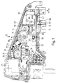
- das erste Ausführungsbeispiel in einem Blick in das Innere des Stellantriebs, wobei sich der erste und der zweite Schieber in einer Endlage befinden, die einem verriegelten Türschloß entspricht,
- Figur 2
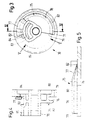
- einen Schnitt entlang der Linie II-II aus Figur 1,
- Figur 3
- eine Ansicht des Zahnrades mit der Steuerkurve für die Klinke, die die beiden Schieber miteinander verbindet,
- Figur 4
- einen Schnitt entlang der Linie IV-IV aus Figur 3,
- Figur 5
- einen Schnitt entlang der Linie V-V aus Figur 3,
- Figur 6
- bei einem konstruktiv etwas anders ausgelegten Ausführungsbeispiel als nach Figur 1 die Position der Klinke relativ zur Steuerkurve nach einer Verriegelung,
- Figur 7
- einen Schnitt entlang der Linie VII-VII aus Figur 6,
- Figur 8
- eine Darstellung ähnlich der nach Figur 6, wobei jedoch auch die Diebstahlsicherung gesetzt ist,
- Figur 9
- einen Schnitt entlang der Linie IX-IX aus Figur 8.
- Figur 10
- eine Darstellung gemäß der aus den Figuren 6 und 8, wobei jedoch bei gesetzter Diebstahlsicherung eine Handhabe im Innern des Fahrzeugs betätigt worden ist,
- Figur 11
- eine Darstellung ähnlich der aus den Figuren 6, 8 und 10, wobei sich die Steuerkurve bei ausgefallenem Elektromotor in der Stellung Diebstahlsicherung befindet, die Türe jedoch einmal entriegelt und wieder verriegelt worden ist,
- Figur 12
- einen Schnitt entlang der Linie XII-XII aus Figur 11,
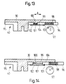
- Figur 13
- in der Verriegelungsstellung die beiden Schieber einer anderen Ausführung, bei der die beiden Schieber über einen Vorsprung und einen Rücksprung miteinander koppelbar sind, wobei der Rücksprung zur Diebstahlsicherung vergrößert werden kann, und
- Figur 14
- die Ausführung nach Figur 13 in der Verriegelungsposition der Schieber und mit gesetzter Diebstahlsicherung.
- Figure 1
- the first embodiment in a view into the interior of the actuator, the first and the second slide being in an end position which corresponds to a locked door lock,
- Figure 2
- 2 shows a section along the line II-II from FIG. 1,
- Figure 3
- a view of the gear with the cam for the pawl, which connects the two sliders,
- Figure 4
- 4 shows a section along the line IV-IV from FIG. 3,
- Figure 5
- 4 shows a section along the line VV from FIG. 3,
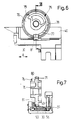
- Figure 6
- in the case of an embodiment which is designed somewhat differently from that of FIG. 1, the position of the pawl relative to the control cam after locking,
- Figure 7
- 6 shows a section along the line VII-VII from FIG. 6,
- Figure 8
- 6 shows a representation similar to that according to FIG. 6, but the anti-theft device is also set,
- Figure 9
- a section along the line IX-IX of Figure 8.
- Figure 10
- 6 shows a representation according to that of FIGS. 6 and 8, but with the anti-theft device set, a handle has been actuated inside the vehicle,
- Figure 11
- 6 shows a representation similar to that of FIGS. 6, 8 and 10, the control cam being in the anti-theft position when the electric motor has failed, but the door has been unlocked and locked again once,
- Figure 12
- 7 shows a section along the line XII-XII from FIG. 11,
- Figure 13
- in the locked position, the two slides of another embodiment, in which the two slides can be coupled to one another via a projection and a recess, the recess being able to be increased to prevent theft, and
- Figure 14
- the embodiment of Figure 13 in the locking position of the slide and with the anti-theft device set.
Bei dem Stellantrieb nach den Figuren 1 und 2 ist in einem zweiteiligen Gehäuse 20 mit einem Gehäusetopf 21 und einem Deckel 22 aus Kunststoff ein erster Elektromotor 23 festgelegt, der über eine auf seiner Welle 24 sitzenden Schnecke 25, ein Schneckenrad 26 und ein einstückig mit diesem Schneckenrad ausgebildetes, jedoch nicht näher dargestelltes Ritzel schließlich ein Kurbelrad 21 antreibt. Von diesem Kurbelrad 27 steht ein sich kegelförmig verjüngender Kurbelzapfen 28 ab, der sich folglich auf einer Kreisbahn bewegt. Die Achse des Schneckenrads 26 ist mit 29 bezeichnet.In the actuator according to Figures 1 and 2, a first
ln dem Gehäuse 20 ist in Richtung des Doppelpfeiles A ein Schieber 30 längsbeweglich geführt, der über U-förmige Ausnehmungen 31, die sich an einem aus dem Gehäuse 20 herausspringenden Ansatz 32 befinden, mit einer nicht näher dargestellten Schubstange verbunden werden kann, die auf einen Türverrieglungsmechanismus in einem Kraftfahrzeug wirkt. An einem sich parallel zum Deckel 22 erstreckenden Ausleger 35 des Schiebers 30, und zwar - in der Draufsicht nach Figur 1 gesehen - an der Unterseite des Auslegers 35 sind zwei Anschläge 33 und 34 vorgesehen, die mit dem Kurbelzapfen 28 zusammenwirken. Man erkennt aus Figur 1, daß der Abstand 8 zwischen den beiden Anschlägen 33 und 34 in Verstellrichtung des Schiebers 30 sehr viel kleiner ist als der Radius der Kurbel, d. h. also sehr viel kleiner als der Abstand des Kurbelzapfens 28 von der Achse 29 des Kurbelrades 27. Dies ermöglich einen großen Hub des Schiebers 30 bei einem gegebenen Kurbelradlus. Der Abstand D der beiden Anschläge 33 und 34 quer zur Verstellrichtung des Schiebers 30 ist nur geringfügig größer als der Durchmesser des Kurbelzapfens 28. In der in Figur 1 dargestellten einen Endlage des Kurbelrades 27 und des Schiebers 30 befindet sich der Kurbelzapfen 28, quer zur Verstellrichtung des Schiebers 30 gesehen, zwischen den beiden Anschlägen 33 und 34. In dieser Endlage ist also der Schieber 30 von dem Kurbelzapfen 28 bzw. dem Kurbelrad 27 vollständig entkoppelt und kann mit der schon erwähnten Schubstange leichtgängig manuell von der gezeigten Endlage in die andere Endlage und wieder zurück umgestellt werden. Gleiches gilt, wenn sich das Kurbelrad 27, der Kurbelzapfen 28 und der Schieber 30 in der anderen Endlage befinden, in der das Kurbelrad um 180° gegenüber der in Figur 1 gezeigten Lage verdreht ist.In the
Wird, ausgehend von der in Figur 1 gezeigten Lage, nun der den Kurbelzapfen 28 antreibende Elektromotor 23 eingeschaltet, so wird der Kurbelzapfen auf seiner kreisförmigen Verstellbahn im Uhrzeigersinn bewegt. Er schlägt dann an dem Anschlag 33 des Schiebers 30 an und nimmt während des folgenden Teils seiner Bewegung Anschlag 33 und Schieber 30 bis in die andere Endlage mit. Nach einem Drehwinkel von 180° wird der Kurbelzapfen wieder stillgesetzt. Beim Wiedereinschalten des Elektromotors 23 schlägt der Kurbelzapfen 28 am Anschlag 34 des Schiebers 30 an und stellt den Schieber wieder in die in Figur 1 gezeigte Endlage zurück, die einer verriegelten Tür entspricht.If, starting from the position shown in FIG. 1, the
Insgesamt wird also deutlich, daß der Kurbelzapfen 28 bei jedem Stellvorgang jeweils um einen Winkel von 180° in gleicher Drehrichtung angetrieben wird. Der Kurbelzapfen 28 ist nur während eines Teils seiner Bewegung mit den Anschlägen 33 bzw. 34 gekoppelt, in den Endlagen nach jeweils einem Drehwinkel von 180° aber von dem Schieber 30 entkoppelt.Overall, it is therefore clear that the crank pin 28 is driven by an angle of 180 ° in the same direction of rotation in each setting process. The crank pin 28 is coupled to the
Der Schieber 30 ist im wesentlichen parallel zu einer Seitenwand des Gehäuses 20 angeordnet und greift mit dem dünnen Ausleger 35 parallel zum Deckel 22 und knapp unterhalb von diesem in den Gehäusetopf 21 hinein. Im Bereich der Seitenwand, an der sich der Schieber befindet, ist in diesem ein zweiter Schieber 40 geführt, wobei die Richtung einer möglichen Bewegung des zweiten Schiebers 40 relativ zum ersten Schieber 30 mit der Richtung des Doppelpfeiles A übereinstimmt. Zur Führung besitzt der zweite Schieber 40 seitlich zwei Leisten 41, die in zur Einführung des zweiten Schiebers 40 in den ersten Schieber 30 am einen Ende offene Nuten 42 des ersten Schiebers 30 eingreifen. Wie man deutlich aus Figur 2 ersieht, ist die eine Seitenwand 43 der Nuten 42 höher als die andere Seitenwand. Entsprechend sind auch die Leisten 41 an der der Seitenwand 43 zugewandten Seite höher als an der anderen Seite, so daß der Schieber 40 nur in einer einzigen relativen Lage zum Schieber 30 in diesen eingeschoben werden kann. Das offene Ende der Nuten 42 befindet sich an der Stirnseite 44 des Schiebers 30. Die beiden Leisten 45 des Schiebers 30, in denen sich die Nuten 42 befinden, sind nur im Bereich des Ansatzes 32 und am anderen Ende der Nuten 42 miteinander verbunden. Der zweite Schieber 40 kann deshalb zwischen der Stirnseite 44 und dem Ansatz 32 des ersten Schiebers 30 mit einem Ansatz 46 durch dieselbe Öffnung 47 in der Seitenwand 48 des Gehäuses 20 nach außen greifen, durch die dies auch der Schieber 30 mit dem Ansatz 32 tut. In einer Nut 49 kann in den Ansatz 46 des zweiten Schiebers 40 eine nicht näher dargestellte Mitnahmescheibe eingesetzt werden, die z. B. über einen Bowdenzug von einer Handhabe im Innern eines Kraftfahrzeugs betätigbar ist. Mitnahmescheibe und zweiter Schieber 40 sind also in Richtung des Doppelpfeiles A formschlüssig miteinander gekoppelt. Im normalen Betrieb liegen die beiden Ansätze 32 und 46 unmittelbar aneinander, wie dies in Figur 1 gezeigt ist.The
Auf der der Seitenwand 48 des Gehäuses 20 abgewandten Seite des zweiten Schiebers 40 ist an diesem senkrecht zur Verstellrichtung der Schieber, die in Figur 1 durch den Doppelpfeil A angedeutet ist, und senkrecht zum Deckel 22 des Gehäuses 20 eine Klinke 50 geführt. Zur Führung greift die Klinke 50 mit zwei seitlichen Leisten 51 in zwei Nuten 52 des Schiebers 40 ein, die durch zwei auf den Schieber einstückig aufgesetzte umgekehrt L-förmige Leisten 53 gebildet werden. Die Klinke besitzt in Führungsrichtung eine Sackbohrung 54, die sich zum Schieber 40 hin in einen Längsschlitz 55 öffnet. Die Breite des Schlitzes ist jedoch geringer als der Durchmesser der Sackbohrung 54, so daß eine in die Sackbohrung 54 eingelegte Schraubendruckfeder 56 nicht durch den Schlitz aus der Sackbohrung 54 herausfallen kann. Die Schraubendruckfeder stützt sich am Boden der Sackbohrung 54 und an einem Widerlager 57 des Schiebers 40 ab, das durch den Längsschlitz 55 in die Sackbohrung 54 hineingreift. In Figur 2 ist mit durchgehenden Linien eine erste Endlage und mit gestrichelten Linien eine zweite Endlage der Klinke 50 angedeutet. Man sieht, daß das Widerlager 57 in jeder Position der Klinke 50 von der dem Längsschlitz 55 gegenüberliegenden Wand 58 überdeckt ist, so daß sich die Schraubendruckfeder 56 sicher in der vorgegebenen Lage an dem Widerlager 57 abstützt. Die Nuten 52 des Schiebers 40 sind beidseitig offen und die Leisten 51 der Klinke 50 durchgehend gleich, so daß die Klinke leicht in Richtung auf die Abstützfläche der Schraubendruckfeder 56 am Widerlager 57 hin in den zweiten Schieber 40 geschoben werden kann. Im Ausleger 35 des ersten Schiebers 30 befindet sich ein rechteckiger Durchbruch 58, in den, sofern er mit der Führung der Klinke 50 fluchtet, die Schraubendruckfeder den Kopf 59 der Klinke 50 soweit hineindrücken kann, bis die Klinke mit einer Stufe an der dem Deckel 22 abgewandten Seite des Auslegers 35 anschlägt. In einem parallel zum Ausleger 35 des Schiebers 30 liegenden Querschnitt, insbesondere in Bewegungsrichtung der Schieber 30 und 40, sind die Maße des Durchbruchs 48 und des Kopfes 59 der Klinke 50 so aufeinander abgestimmt, daß nur ein geringes Spiel zwischen ihnen besteht.On the side of the
Wenn die Klinke 50 mit ihrem Kopf 59 in den Durchbruch 58 des Schiebers 30 eingreift, sind also die Schieber 30 und 40 in beide Bewegungsrichtungen miteinander gekoppelt. Aus dem Aneinanderliegen der beiden Ansätze 32 und 46 geht außerdem hervor, daß aus der in Figur 1 gezeigten Endlage der beiden Schieber, die einem verriegelten Türschloß entspricht, der Schieber 30 den Schieber 40 mit dem Ansatz 32 unabhängig von der Klinke 50 mit in die Endlage nehmen kann, die einer entriegelten Tür entspricht. Dabei spielt es keine Rolle, ob der Schieber 30 manuell über den Schließzylinder oder von dem Elektromotor 23 verstellt wird. Beim Verriegeln der Türschlösser, also bei einer Verstellung des Schiebers 30 von der zweiten Endlage in die in Figur 1 gezeigte Endlage, wird der zweite Schieber 40 vom ersten Schieber 30 über die Klinke 50 mitgenommen, wobei es wiederum keine Rolle spielt, ob der erste Schieber 30 von Hand oder vom Elektromotor verstellt wird.If the
Bei Eingriff der Klinke 50 in den Durchbruch 58 ist es möglich, auch mit der Innenverriegelungshandhabe eine Kraftfahrzeugtür zu entriegeln oder zu verriegeln. Ist die lüre verriegelt und wird nun die Innenverriegelungshandhabe betätigt, so wird über die nicht dargestellte Mitnahmescheibe, die sich in der Nut 49 des Ansatzes 46 des zweiten Schiebers 40 befindet, der zweite Schieber 40 und über die Klinke 50 der erste Schieber 30 mitgenommen, der die Bewegung auf das Türschloß überträgt. Bei einem Verriegelungsvorgang nimmt der Schieber 40 den ersten Schieber 30 über den Ansatz 46 bzw. die Klinke 50 mit.When the
Während bei einer Verriegelung einer Kraftfahrzeugtür von innen jederzeit auch wieder deren Entriegelung von innen möglich sein sollte, ist es erwünscht, bei einer Verriegelung von außen die Möglichkeit zu haben, eine anschließende Entriegelung von innen unmöglich zu machen. Es soll damit vermieden werden, daß bei einem Diebstahlversuch nach dem Einschlagen einer Fensterscheibe des Kraftfahrzeugs durch eine Betätigung einer Innenverriegelungshandhabe die Türen entriegeit werden und dann das Kraftfahrzeug leicht zugänglich ist.While locking a motor vehicle door from the inside should at any time enable it to be unlocked again from the inside, it is desirable to be able to make a subsequent unlocking from the inside impossible when locking from the outside. It is to be avoided in the event of an attempted theft after being hit Window pane of the motor vehicle can be unlocked by actuating an internal locking handle and then the motor vehicle is easily accessible.
Um diese Diehstahlsicherung zu ermöglichen, ist eben die schon beschriebene Klinke 50 vorhanden, die von einem zweiten Elektromotor 65 aus dem Durchbruch 58 des Schiebers 30 zurückgezogen werden kann, sofern sich die beiden Schieber 30 und 40 in der Verriegelungsposition befinden und der Elektromotor 65 an Spannung gelegt wird. Der Elektromotor 65 treibt ähnlich wie der Elektromotor 23 über eine auf seiner Welle 66 sitzenden Schnecke 67, über ein Schneckenrad 68 und über ein einstückig mit diesem Schneckenrad ausgebildetes Ritzel 69 schließlich ein Zahnrad 70 an, das knapp unterhalb des Auslegers 35 des Schiebers 30 mit einem Zahnkranz 71 versehen ist und, vom Ausleger 35 aus gesehen, jenseits des Zahnkranzes 71 eine Steuerkurve 75 aufweist, die sich im Abstand zum Zahnkranz 71 auf der diesem Zahnkranz abgewandten Seite eines radialen Flansches 76 des Zahnrads 10 befindet.In order to enable this anti-theft device, the
Während in Figur 2 das Zahnrad 70 nur schematisch gezeichnet ist, gehen nähere Einzelheiten aus den Figuren 3 bis 5 hervor. Die Steuerkurve 75 erstreckt sich über einen Winkel von etwa 205° und besteht aus einer von der Unterseite des Zahnkranzes 71 aus ansteigenden Rampe 77, die sich über einen Winkel von etwa 60° erstreckt und einem sich an die Rampe anschließenden Plateauabschnitt 78, dessen Länge etwa 245° beträgt. Am Ende 79 des Plateauabschnitts bricht die Steuerkurve abrupt ab. Der die Steuerkurve 75 tragende Flansch 76 ist gegen den Zahnkranz 71 hin durch eine umlaufende Nut 80, die radial nach außen offen ist, von dem Zahnkranz 11 freigeschnitten. Die Nut 80 ist breiter als ein Kurvenfolger 81, der einstückig mit der Klinke 50 ausgebildet ist und senkrecht zu deren Führungsrichtung zu der Steuerkurve 75 hin von der Klinke 50 absteht und sich, wie aus Figur 2 ersichtlich, bei in den Schieber 30 eingeschnappter Klinke 50 knapp unterhalb des Zahnkranzes 71 auf Höhe der Nut 80 befindet. Die Nut 80 setzt sich auch unterhalb der Rampe 77 fort, nimmt dort jedoch entsprechend der Schrägstellung der Rampe in ihrer Breite zunächst kontinuierlich ab, hat dann noch einmal einen Abschnitt mit einer konstanten Breite, weil die Rampe 77 dünner wird, und nimmt schließlich in ihrer Breite bis nahe auf den Wert Null ab. Daß die Rampe 71 an ihrem Fuß dünner ist als im Abstand dazu hat werkzeugtechnische Gründe. Die Rampe ist nämlich nicht nur radial außen, sondern auch an ihrem Fuß 82 von dem übrigen Material des Zahnrades 70 getrennt. Um jeaoch ein glattes Auflaufen des Kurvenfolgers 81 auf die Rampe 77 zu gewährleisten, darf der Abstand zwischen dem Fuß 82 der Rampe 77 und dem übrigen Material des Zahnrades 70 nur gering sein. Dieser geringe Abstand muß mit einem Abschnitt des Formwerkzeugs erzeugt werden, der nur sehr dünn und deshalb bruchgefährdet ist. Dadurch, daß die Rampe an ihrem Fuß dünner ist als im Abstand dazu, wird die Länge dieses Werkzeugabschnitts in Umlaufrichtung klein und damit die Bruchgefahr vermindert. Die Rampe 77 ist auch radial innen durch einen Freischnitt 83, der durch einen Durchbruch 84 im Zahnkranz 71 des Zahnrads 70 entformbar ist, vom übrigen Material des Zahnrads 70 getrennt. Wie man in Figur 3 erkennen kann, beginnt dabei der Freischnitt 83, in Umlaufrichtung betrachtet, schon im Abstand vor dem Fuß 82 der Rampe 77 und endet kurz hinter dem Übergang zwischen der Rampe 77 und dem Plateauabschnitt 78 innerhalb des Plateauabschnitts 78. Nur an diesem übergang ist also die Rampe 77 mit dem übrigen Material des Zahnrads 70 verbunden. Sie kann deshalb von dem Zahnkranz 71 gut wegfedern.While the
Das Zahnrad 70 trägt auch einen radialen Nocken 85, mit dem ein im Gehäuse 20 unterbrachter Endlagenschalter 86 für den Elektromotor 65 betätigt werden kann. Der Schalter 86 ist ein Wechsler, der von dem Nocken 85 so gesteuert wird, daß der immer in dieselbe Drehrichtung laufende Elektromotor 65 jeweils nach einer Drehung des Zahnrades 70 von etwa 180° abgeschaltet wird. In Umlaufrichtung sind die Lage des Nockens 85 und die Lage der Steuerkurve 75 so aufeinander abgestimmt, daß sich der Kurvenfolger 81 der Klinke 50 in der einen Ruhelage des Zahnrads 70 kurz vor der Rampe 77 und in der anderen Ruhelage des Zahnrads 70 kurz vor dem Ende 79 des Plateauabschnitts 78 befindet, sofern die Schieber 30 und 40 in der Verriegelungsposition stehen.The
Die Funktionsweise des elektromotorischen Stellantriebs nach den Figuren 1 bis 5 sei nun auch mit Hilfe der Figuren 6 bis 12 näher erklärt. Man erkennt in diesen Figuren ebenfalls den ersten Schieber 30, den zweiten Schieber 40, die Klinke 50 mit dem Kopf 59 und dem Kurvenfolger 81 sowie das Zahnrad 70 mit dem Flansch 76 als Träger der Steuerkurve 75 mit der Rampe 77 und dem Plateauabschnitt 78. Die Figuren 6 und 7 zeigen die Schieber 30 und 40 in der Verriegelungsposition, aus der sie durch eine Bewegung nach rechts (in der Ansicht nach Figur 6 betrachtet) in die Entriegelungsposition gebracht werden können. In dem Zustand nach den Figuren 6 und 7 greift die Klinke 50 mit ihrem Kopf 59 in den ersten Schieber 30 ein. Wird nun die Innenverriegelungsnandhabe betätigt, so nimmt der Scnieber 40 über die Klinke 50 den Schieber 30 in die Entriegelungsstellung mit, so daß das Schloß entriegelt ist. Es war also keine Diebstahlsicherung gesetzt. Soll verriegelt und die Diebstahlsicherung gesetzt werden, so wird durch ein längeres Betätigen des Schließzylinders, durch ein nochmaliges Betätigen des Schließzylinders oder auch durch ein Betätigen des Schließzylinders über einen bestimmten Weg hinaus ein Signal gegeben, aufgrund dessen der zweite Elektromotor 65 an Spannung gelegt wird, wenn sich der Schieber 30 in der Verriegelungsposition befindet. Der Elektromotor 65 dreht das Zahnrad 70, in der Ansicht nach Figur 6 betrachtet, im Uhrzeigersinn um 180° bis er von dem Schalter 86 ausgeschaltet wird. Die Steuerkurve 75 fährt mit der Rampe 77 unter den Kurvenfolger 81 der Klinke 50 und zieht diese aus dem Durchbruch 58 des Schiebers 30 heraus, wobei der Weg der Klinke 50 durch die Höhe des Plateauabschnitts 78 der Steuerkurve 75 bestimmt ist. Beim Abschalten des Elektromotors 65 befindet sich der Kurvenfolger 81 der Klinke 50 nahe am Ende 79 des Plateauabschnitts 78, während er vor der 180°-Drehung des Zahnrads 70 kurz vor der Rampe 77 stand. Wird nun, ausgehend von dem Zustand nach den Figuren 8 und 9, eine lnnenverriegelungshandhabe des Fahrzeugs betätigt, so wird nur der Schieber 40 nach rechts in die Entriegelungsstellung bewegt. Die Position des Schiebers 30 dagegen verändert sich nicht, so daß das Türschloß verriegelt bleibt. Bei der Bewegung des Schiebers 40 kann die Klinke 50 ohne weiteres von dem Plateauabschnitt 78 der Steuerkurve 75 tangential wegbewegt werden. Sobald der Kurvenfolger 81 den Plateauabschnitt 78 verlassen hat, stützt sich die Klinke an einer Wand des Schiebers 30 ab, so daß sie ihre Höhenlage bezüglich der Steuerkurve 75 im wesentlichen beibehält, und rutscht mit dem Schieber 40 am Schieber 30 entlang. Wird die Innenverriegelungshandhabe wieder zurückbewegt, so bewegt sich auch der Schieber 40 wieder in die in Figur 8 gezeigte Position, wobei der Kurvenfolger 81 wieder auf den Plateauabschnitt 78 der Steuerkurve 75 gelangt. Um dieses Auflaufen auf den Plateauabschnitt 78 zu erleichtern, ist dieser, wie insbesondere die Figur 4 zeigt, radial außen mit einer Schräge 87 versehen. Verbleiben dagegen die Innenverriegelungshandhabe und mit ihr der Schieber 40 in der Entriegelungsstellung, so wird bei einer Entriegelung von außen der Schieber 30 nachgestellt, wobei in der Entriegelungsposition des Schiebers 30 die Klinke 50 aufgrund der Kraft der Feder 56 in den Durchbruch 48 des Schiebers 30 einrastet und damit beide Schieber wieder gekoppelt sind. Die Position der einzelnen Teile bei gesetzter Diebstahlsicherung und nach einer Betätigung der Innenverriegelungshandhabe in Richtung Entriegelung ist in Figur 10 gezeigt.The operation of the electromotive actuator according to Figures 1 to 5 will now be explained in more detail with the help of Figures 6 to 12. You can also see in these figures the
Nun kann es vorkommen, daß die Stromversorgung für den zweiten Elektromotor 65 ausfällt. Das Zahnrad 70 kann sich dann in der Ruhelage nach Figur 6 oder in der Ruhelage nach Figur 8, aber auch in jeder Zwischenlage befinden. Immer soll es möglich sein, die beiden Schieber 30 und 40 aus ihrer Entriegelungsposition in die Verriegelungsposition zu bringen, um die Türe des Fahrzeugs zumindest verriegeln, wenn auch nicht gegen Diebstahl sichern zu können. Dabei muß vor allem der Weg für den Kurvenfolger 81 der Klinke frei sein. Wenn sich das Zahnrad in der Position nach Figur 6 befindet, die ja der nicht gesetzten Diebstahlsicherung entspricht, kann die Klinke 50 frei bewegt werden, so daß eine Verriegelung möglich ist. Dies gilt auch, wenn sich der keine Steuerkurve tragende Umfangsabschnitt des Zahnrads 70 im Weg des Kurvenfolgers 81 betindet. Nimmt das Zahnrad 70 dagegen seine andere Ruhelage ein, die in den Figuren 8, 10 und 11 gezeigt ist, so ermöglicht es die Nut 80 zwischen dem Flansch 76 und dem Zahnkranz 71 des Zahnrads 70, daß eine Verriegelung möglich ist. Denn während dieser Verriegelung kann der Kurvenfolger 81 in diese Nut hineingeschoben werden, wie dies insbesondere aus Figur 12 hervorgeht. Befindet sich gerade die Rampe 77 im Weg des Kurvenfolgers 81, so hebt dieser die Rampe aufgrund deren federnder Eigenschaften entweder nur etwas hoch oder fährt ganz unter sie hindurch. Damit ist eine Verriegelung in jeder Position des Zahnrads 70 möglich. Insbesondere aus Figur 6 geht hervor, daß die Drehrichtung des Zahnrads 70 beim Auflaufen des Kurvenfolgers 81 auf die Rampe 77 so gewählt ist, daß eine beim Auflaufen auftretende Kraftkomponente in Bewegungsrichtung der Schieber 30 und 40 in Verriegelungsrichtung wirkt. Da die Schieber in dieser Richtung an einem Anschlag anliegen, kann diese Kraft die Lage der Schieber nicht beeinflussen. Ebenso bringt es diese Drehrichtung mit sich, daß beim Ausfall der Stromversorgung die Rampe 77 unterfahren werden kann und der Kurvenfolger 81 nicht auf die Rampe aufläuft, sollte diese sich zufälligerweise im Bereich des Kurvenfolgers befinden. Damit kann man erreichen, daß bei Ausfall der Spannungsversorgung für den Elektromotor 65 über die Innenverriegelungshandhabe auf keinen Fall die Diebstahlsicherung gesetzt wird.Now it can happen that the power supply for the second
Bei dem elektromotorischen Stellantrieb nach den Figuren 13 und 14 sind wiederum ein erster Schieber 30 und ein zweiter Schieber 40 vorhanden. Der zweite Schieber besteht aus zwei Teilen 95 und 96, die in Bewegungsrichtung der Schieber, die wiederum durch den Doppelpfeil A angedeutet ist, einen Abstand voneinander haben. Der Teil 96 möge als Mitnehmer bezeichnet werden, da er bei gegenüber dem Schieber 30 ruhenden Teil 95 des Schiebers 40 von einem Elektromotor 97 relativ zum Teil 95 in Richtung des Pfeiles A bewegt werden kann. Dazu ist der Mitnehmer 96 mit einem Zahnstangenabschnitt 98 versehen, in den ein nicht dargestelltes Ritzel des Elektromotors 97 eingreift. Durch den Abstand zwischen den Teilen 95 und 96 des Schiebers 40 wird ein Rücksprung 99 gebildet, in den der Schieber 30 mit einem Vorsprung 100 eingreift. Die beiden Teile 95 und 96 des Schiebers 40 werden durch eine Schraubenfeder 101 aufeinander zu gezogen. Außerdem ist am Teil 95 des Schiebers 40 eine Rastfeder 102 befestigt, die über den Mitnehmer 96 greift und mit einem Raster 103 in eine Rastaufnahme 104 des Mitnehmers 96 eingreifen kann. Die Verrastung wird bei einer bestimmten Krafteinwirkung in Bewegungsrichtung der Schieber gelöst, so daß Rastfeder, Raster und Rastaufnahme als Grenzkraftgesperre bezeichnet werden können.In the electromotive actuator according to FIGS. 13 and 14, a
Wie bei dem elektromotorischen Stellantrieb nach den Figuren 1 bis 12 kann auch bei demjenigen nach den Figuren 13 und 14 der Schieber 30 an einem Gehäuse geführt sein, während die Teile 95 und 96 des Schiebers 40 unabhängig voneinander am Schieber 30 geführt sein mögen.As in the electromotive actuator according to FIGS. 1 to 12, the
Der Elektromotor 97 ist ein drehrichtungsumkehrbarer Motor, der zum Verriegeln und zum Setzen einer Diebstahlsicherung in die eine Richtung und zum Zurücksetzen der Diebstahlsicherung und Entriegeln in die andere Richtung antreibbar ist.The
ln dem in Figur 13 gezeigten Zustand mögen sich die Schieber 30 und 40 in ihrer Verriegelungsposition befinden. Wird nun der Motor in Richtung des Pfeiles G eingeschaltet, so schiebt er den Mitnehmer 96, in der Ansicht nach Figur 13, nach links. Der Mitnehmer 96 nimmt über den Vorsprung 100 den Schieber 30 mit, so daß das Schloß entriegelt wird. Beim Verriegeln dreht der Elektromotor 97 in die andere Richtung H, wobei vom Teil 96 des Schiebers 40 über die Schraubenfeder 101 der andere Teil 95 und der Schieber 30 mitgenommen werden, bis diese die Verriegelungsposition einnehmen. Bei einem Weiterdrehen des Elektromotors in dieselbe Richtung wird unter Verstärkung der Spannung der Feder 101 nur noch der Mitnehmer 96 verstellt, bis der Raster 103 in die Rastaufnahme 104 eingreift. Die Grenzkraftlösung dieser Verrastung ist so gewählt, daß die gespannte Feder 101 allein die Verrastung nicht lösen kann. Die Teile verbleiben deshalb in der in Figur 14 gezeigten Lage, in der der Rücksprung 99 wesentlich größer als der Vorsprung 100 ist. Wird nun eine Innenverriegelungshandhabe, die mit dem Teil 95 des Schiebers 40 verbunden ist, betätigt, so werden zwar die Teile 95 und 96 des Schiebers 40 nach links bewegt, der Schieber 30 aber verbleibt in Ruhe. Eine Entriegelung des Schlosses ist nicht möglich.In the state shown in Figure 13, the
Beim Entriegeln aus dem in Figur 14 gezeigten Zustand heraus, wird, da der Bewegung des Teils 95 des Schiebers 40 ein gewisser Widerstand von der Innenverriegelungshandhabe entgegengesetzt wird, zunächst die Verrastung gelöst, d. h. die Diebstahlsicherung zurückgesetzt, und dann das Schloß unter Mitnahme des Schiebers 30 entriegelt.When unlocking from the state shown in FIG. 14, since the movement of the
Denkbar ist es jedoch auch, daß aus dem Zustand nach Figur 14 heraus zunächst nur die Teile 95 und 96 des Schiebers 40 bis zur Entriegelungsendlage des Teils 95 verschoben werden, ehe der Mitnehmer 96 den Schieber 30 nach Lösen der Verrastung zwischen dem Raster 103 und der Rastausnehmung 104 mitnimmt.However, it is also conceivable that only the
Unter Umständen kann man auf die Schraubenfeder 101 verzichten, wenn man für den Raster 103 eine zweite Rastausnehmung im Mitnehmer 96 vorsieht, in die der Raster 103 in der in Figur 13 gezeigten Lage des Mitnehmers 96 eingreift. Dann nimmt nämlich beim Verriegeln der Mitnehmer 96 über diese weitere Verrastung das Teil 95 des Schiebers 40 und den Schieber 30 mit.It may be possible to dispense with the
Schließlich ist es sogar möglich ohne weitere Verrastung auf die Schraubenfeder 101 zu verzichten, wenn man akzeptiert, daß bei einer Verriegelung zunächst unter einer Vergrößerung des Rücksprungs 99 nur der Mitnehmer 96 bewegt wird, bis der Raster 103 in die Rastausnehmung 104 eingreift und dann auch das Teil 95 des Schiebers 40 und der Schieber 30 verstellt werden. Bei einer Entriegelung würden wiederum nur die Teile 95 und 96 des Schiebers 40 bewegt, ehe der Schieber 30 mitgenommen wird. Es würde also jeweils die Diebstahlsicherung schon vor dem Verriegeln gesetzt und erst nach dem Entriegeln zurückgesetzt.Finally, it is even possible to dispense with the
Claims (42)
- An electromotive actuator for a central door locking system of a motor vehicle with a housing (20), with a first slide (30), which is adjustable by an electric motor (23) between two end positions, which can be connected with a door lock of the motor vehicle independent of the direction and which, preferably, is decoupled from the electric motor (23) in the end positions so that it is easily movably adjustable manually adjusted between its end positions, characterized in that a second slide (40) can be coupled with a handle in the inside of the motor vehicle at least for unlocking, in that the second slide (40) can be coupled with the first slide (30) by a latch (50) which is adjustably guided at one of the two slides (40) transversely to the moving direction of the slides (30,40), engages into the other slide (30) under the effect of a spring element (56), in that the latch (50) can be withdrawn by a second electric motor (65) by means of a control device (75) in order not to engage into the other slide (30) against the effect of the spring element (56) from one coupling position into a theft protection position in order to protect against theft and in that the latch (50) together with the slide (40) at which said latch is guided, can be moved away from the control device (75) in the theft protection position.
- An electromotive actuator for a central door locking system of a motor vehicle with a housing (20) with a first slide (30) which is adjustable by an electric motor (23) between two end positions which can be connected with a door lock of the motor vehicle independent of the direction and which preferably is decoupled from the electric motor (23) in the end positions so that it is easily movable adjustable manually between its end positions , characterized in that a second slide (40) can be coupled with a handle in the inside of the motor vehicle for unlocking, in that the first slide (30) and the second slide (40) engage into each other with a jut (100) and a recess (99) transversely to their moving direction and in that in order to protect theft, a carrier (96) of one of the two slides (40) can be moved relative to the slide (40) in moving direction of the two slides (30,40) by an electric motor (97) in order to form a lost motion by reducing the jut (100) or enlarging the recess (99).
- An electromotive actuator according to claim 1 or 2, characterized in that in each adjusting process a crank (28) is adjustable by a first electric motor (23) by a swivelling angle of 180 degrees each time in the same turning direction that the first slide (30) is adjustable between the two end positions by this crank (25) and in that said crank (25) is coupled with the first slide (30) only during a period of its swivelling direction, however, is decoupled of the first slide (30) in the end positions after a swivelling angle of 180 degrees each time.
- An electromotive actuator according to one of the preceding claims, characterized in that the second slide (40) can be entrained by the first slide (30) independently of the latch (50) in unlocking direction.
- An electromotive actuator according to claim 4, characterized in that the catching is effected by lateral extensions (32,46) of the slides (30,40).
- An electromotive actuator according to one of the preceding claims, characterized in that the control device is a control curve (75) with a ramp (77).
- An electromotive actuator according to claim 6, characterized in that the ramp (77) moves in such a direction during the ascent of the latch (60) which corresponds to the moving direction of the slides (30,40) during the locking operation.
- An electromotive actuator according to claim 6 or 7, characterized in that the latch (50) can be pushed beneath the control curve (75) while the slides (30,40) are adjusted from the unlocking into the locking position.
- An electromotive actuator according to claim 8, characterized in that the ramp (77) of the control curve is formed resiliently in such a way that the latch (50) can be pushed beneath the ramp (77) or can be pushed through beneath the ramp (77) during the the slides are shifted from the unlocking into the locking position.
- An electromotive actuator according to claim 9, characterized in that the ramp (77) is also cut free in the inside, this means at the lateral edge, which is turned away from the latch (50).
- An electromotive actuator according to claim 10, characterized in that the free cut (83) is slightly longer in the inside than the ramp (77).
- An electromotive actuator according to one of the claims 9 to 11, characterized in that the ramp (77) is thinner at its foot (82) than in the distance towards its foot (82).
- An electromotive actuator according to one of the claims 6 to 12, characterized in that the control curve (75) is situated at a gearwheel (70) which can be driven by the second electric motor (65).
- An electromotive actuator according to claim 13, characterized in that the latch (50) can be moved away from the control curve towards the direction of the axis of the gearwheel (70).
- An electromotive actuator according according to claim 14, characterized in that the control curve (75) is situated behind the gear ring (71) of the gearwheel (70), seen in the direction in which the latch (50) can be moved by the control curve (75).
- An electromotive actuator according to one of the claims 13 to 15, characterized in that the control curve (75) comprises a plane section (78) without a change of height following the ramp (77).
- An electromotive actuator according to claim 16, characterized in that the plane section (78) comprises a slope (87) declining in radial direction at its outside radial edge.
- An electromotive actuator according to one of the claims 13 to 17, characterized in that the ramp (77) extends over an angle of approximately 60 degrees in circulation direction of the gearwheel (70).
- An electromotive actuator according to one of the claims 13 to 18, characterized in that the second electric motor (65) is actuatable only in one direction of rotation and characterized in that the gearwheel (70) can be driven by the electric motor (65) only in one single direction of rotation.
- An electromotive actuator according to claim 19, characterized in that the second electric motor (65) can be switched on by the spring element (56) for pulling back the latch (50) as well as for pushing forward the latch, wherein the gearwheel can be turned by 180 degrees after each time the electric motor is switched on.
- An electromotive actuator according to claim 20, characterized in that the control curve (75) with its ramp (77) and its plane section (78) extends over an angle of 205 degrees in circulation direction of the gearwheel (70).
- An electromotive actuator according to claim 19, characterized in that the second electric motor (65) can be switched on only for pulling back the latch, wherein the gearwheel (70) can preferably be turned by 360 degrees after each time the electric motor (65) is switched on.
- An electromotive actuator according to one of the claims 20 to 22, characterized in that the second electric motor (65) can be switched off, after each time it was switched on, by an end switch (86) which can be worked by the gearwheel (70) and in that the moment when it is switched off, respectively, when the end switch (86) is switched off and the position and length of the control curve (75) are coordinated with each other in such a way that the latch (50), when in locking position of the slides (30,40) and in a resting position of the gearwheel (70), is situated near the end (79) turned away from the ramp of the plane section (78), on said plane section or in a small distance towards the ramp (77).
- An electromotive actuator according to one of the preceding claims, characterized in that the spring element (56) is a helical spring situated in a blind-end bore (54) of the latch (50) and supporting itself at a stud (57) of the slide (40) guiding the latch, which stud (57) projects into the blind-end bore 54 by a radial slot (55), because the blind-end bore (54) is open to the outside.
- An electromotive actuator according to one of the preceding claims, characterized in that the spring element (56) presses the latch (50) against a stop (35) of the slide (30), which does not guide the latch (50) while the slides (30, 40) are in the coupled state.
- An electromotive actuator according to claims 24 and 25, characterized in that, also when the latch (50) abuts the stop (35), the wall of the blind-end bore (54) situated opposite of the radial slot (55), protrudes the stud (57) supporting the helical spring (56).
- An electromotive actuator according to one of the preceding claims, characterized in that the latch (50) is guided in two grooves (53) with two rails situated opposite each other, each of which is formed by a rail (53), L-shaped in cross section and which is placed upon the slide (40).
- An electromotive actuator according to one of the preceding claims, characterized in that the latch (50) is guided at the second slide (40).
- An electromotive actuator according to one of the claims 1 to 27, characterized in that the latch (50) is guided at the first slide (30).
- An electromotive actuator according to claims 27 or 28, characterized in that the second slide (40) can be operated by a handle in the inside of the motor vehicle only in the sense of unlocking the door lock.
- An electromotive actuator according to claim 30, characterized in that the slides can be coupled with the handle in the inside of the motor vehicle by means of a carrier and that the carrier is situated between said slides in moving direction of the slides (30,40).
- An electromotive actuator according to claim 27 or 28, characterized in that the slides (30,40) can be coupled with a handle in the inside of the motor vehicle by means of a carrier, characterized in that the second slide (40) can be directly coupled with the carrier form-fittingly in both moving directions and that the carrier can be operated by means of a handle in the inside of the motor vehicle in the sense of locking and unlocking the door lock.
- An electromotive actuator according to one of the preceding claims, characterized in that the one slide (30) is guided at the housing (20) and the other slide (40) is guided at the first slide (30).
- An electromotive actuator according to claim 33, characterized in that the first slide (30) is guided at the housing (20) and the second slide 840) is guided at the first slide (30).
- An electromotive actuator according to claim 33 or 34, characterized in that the one slide (30) is provided with two narrow grooves (42) and the other slide (40) with two narrow rails (41), which engage into the grooves (42) and that one groove (42) and a respective rail (41) is lower at one side than at the other one.
- An electromotive actuator according to claim 2 or 3, characterized in that the carrier (96) can be moved away against the effect of a spring element (101), which supports itself at the respective slide (40).
- An electromotive actuator according to one of the claims 2, 3 or 36, characterized in that the carrier (96) can be coupled in one position with the corresponding slide (40) by a locking device for limited power (102, 103, 104).
- An electromotive actuator according to one of the claims 2, 3, 36 or 37, characterized in that the one slide (40) and the other carrier (96) are guided at the other slide (30) independent of each other.
- An electromotive actuator according to one of the claims 2, 3 or 36 to 38, characterized in that the carrier (96) is part of the second slide (40).
- An electromotive actuator according to one of the claims 2, 3, or 36 to 39, characterized by one single electric motor, which direction of rotation can be reversed, with which electric motor the carrier (96) can be adjustably coupled.
- An electromotive actuator according to claim 40, characterized in that gearwheel being adjustable by the electric motor (97) intermeshes a toothed rack of the carrier (96).
- An electromotive actuator according to claim 40 and 41, characterized in that the carrier (96) can be adjusted after a locking of the door lock by a further turning of the electric motor into the same direction like in the locking operation.
Applications Claiming Priority (3)
| Application Number | Priority Date | Filing Date | Title |
|---|---|---|---|
| DE4125448 | 1991-08-01 | ||
| DE4125448A DE4125448C2 (en) | 1991-08-01 | 1991-08-01 | Electromotive actuator for a central door locking system of a motor vehicle |
| PCT/EP1992/001719 WO1993003245A1 (en) | 1991-08-01 | 1992-07-29 | Electromotor actuator for the central door locking system of a motor vehicle |
Publications (2)
| Publication Number | Publication Date |
|---|---|
| EP0551491A1 EP0551491A1 (en) | 1993-07-21 |
| EP0551491B1 true EP0551491B1 (en) | 1995-10-04 |
Family
ID=6437456
Family Applications (1)
| Application Number | Title | Priority Date | Filing Date |
|---|---|---|---|
| EP92916936A Expired - Lifetime EP0551491B1 (en) | 1991-08-01 | 1992-07-29 | Electromotor actuator for the central door locking system of a motor vehicle |
Country Status (7)
| Country | Link |
|---|---|
| US (1) | US5453671A (en) |
| EP (1) | EP0551491B1 (en) |
| JP (1) | JPH06502234A (en) |
| BR (1) | BR9205361A (en) |
| DE (1) | DE4125448C2 (en) |
| ES (1) | ES2078058T3 (en) |
| WO (1) | WO1993003245A1 (en) |
Families Citing this family (12)
| Publication number | Priority date | Publication date | Assignee | Title |
|---|---|---|---|---|
| DE4439479A1 (en) * | 1994-11-08 | 1996-05-09 | Bocklenberg & Motte Bomoro | Motor vehicle door lock with central locking drive |
| GB2306552B (en) * | 1995-10-25 | 1999-11-17 | Rockwell Lvs | Vehicle door lock actuator |
| US5715713A (en) * | 1996-01-11 | 1998-02-10 | General Motors Corporation | Door latch locking actuator assembly |
| DE19611535A1 (en) * | 1996-03-23 | 1997-09-25 | Bosch Gmbh Robert | Device and method for electronically monitoring an adjustment drive arranged in a vehicle |
| DE69831398T2 (en) | 1997-02-04 | 2006-06-14 | Intier Automotive Closures Inc | MOTOR VEHICLE DOOR LOCKING SYSTEM WITH SEPARATED MOTOR DRIVEN DOOR INTERIOR AND OUTSIDE LOCKING DEVICES |
| DE19958288A1 (en) * | 1999-12-03 | 2001-06-13 | Bosch Gmbh Robert | Electromotive actuator for a motor vehicle lock |
| EP1113132B1 (en) | 1999-12-31 | 2008-01-09 | Brose Schliesssysteme GmbH & Co. KG | Electric motor actuator for a motor vehicle lock |
| GB0019017D0 (en) * | 2000-08-04 | 2000-09-27 | Meritor Light Vehicle Sys Ltd | Actuator |
| JP4511930B2 (en) * | 2002-08-20 | 2010-07-28 | マグナ クロージャーズ インコーポレイテッド | Door latch actuator |
| DE202010013611U1 (en) * | 2010-09-27 | 2011-12-28 | BROSE SCHLIEßSYSTEME GMBH & CO. KG | Motor vehicle lock |
| DE202011003497U1 (en) * | 2011-03-04 | 2012-06-05 | Kiekert Ag | Motor vehicle door lock |
| DE102019109488A1 (en) * | 2019-04-10 | 2020-10-15 | Kiekert Aktiengesellschaft | LOCKING SYSTEM FOR A MOTOR VEHICLE |
Family Cites Families (20)
| Publication number | Priority date | Publication date | Assignee | Title |
|---|---|---|---|---|
| IT1131405B (en) * | 1979-03-24 | 1986-06-25 | Kiekert Soehne Arn | CENTRALIZED CLOSING DEVICE FOR MOTOR VEHICLE DOORS |
| US4440006A (en) * | 1979-03-24 | 1984-04-03 | Kiekert Gmbh & Co. Kommanditgesellschaft | Antitheft central lock system for a motor vehicle |
| DE3120000A1 (en) * | 1981-05-20 | 1982-12-16 | Robert Bosch Gmbh, 7000 Stuttgart | Drive for adjusting a member, especially of a bolt element belonging to a motor vehicle |
| DE3210924A1 (en) * | 1982-03-25 | 1983-09-29 | Fichtel & Sachs Ag, 8720 Schweinfurt | LOCKING DEVICE FOR THE ACTUATOR OF AN ACTUATOR, ESPECIALLY FOR CENTRAL LOCKING DEVICE ON MOTOR VEHICLES |
| DE3627893A1 (en) * | 1986-08-16 | 1988-02-18 | Swf Auto Electric Gmbh | ACTUATING DEVICE, IN PARTICULAR FOR DOOR LOCKING IN MOTOR VEHICLES |
| DE3629558A1 (en) * | 1986-08-30 | 1988-03-03 | Vdo Schindling | Electromotive actuating element |
| DE3629557A1 (en) * | 1986-08-30 | 1988-03-03 | Vdo Schindling | ELECTRIC MOTOR ACTUATOR |
| DE3716507A1 (en) * | 1987-03-07 | 1988-09-15 | Vdo Schindling | DEVICE FOR ACTUATING A LOCKING DEVICE HAVING TWO END LOCATIONS ON A MOTOR VEHICLE DOOR LOCK THROUGH A LEVER |
| JP2512880B2 (en) * | 1987-04-03 | 1996-07-03 | 株式会社ニコン | EC element with electrodes taken out from the third electrode layer |
| FR2614643B1 (en) * | 1987-04-29 | 1989-07-28 | Rockwell Cim | ASSEMBLY OF A DOOR LOCK AND AN ANTI-THEFT AND ANTI-AGGRESSION LOCKING DEVICE THEREOF AND LOCK PART OF THIS ASSEMBLY |
| JPH0735708B2 (en) * | 1987-11-30 | 1995-04-19 | 株式会社大井製作所 | Door lock device for automobile |
| DE3806326C1 (en) * | 1988-02-27 | 1989-01-26 | Daimler-Benz Ag, 7000 Stuttgart, De | |
| GB2217380B (en) * | 1988-04-16 | 1992-03-04 | Rockwell Automotive Body Co | Vehicle door lock actuator. |
| FR2631368B1 (en) * | 1988-05-11 | 1990-08-24 | Rockwell Cim | CONDEMNATION ACTUATOR FOR LOCK, PARTICULARLY FOR MOTOR VEHICLE DOORS |
| US4926337A (en) * | 1988-07-13 | 1990-05-15 | Bryant Grinder Corporation | Automatic workpart centering mechanism for a chuck |
| DE3902873A1 (en) * | 1988-08-13 | 1990-02-15 | Kiekert Gmbh Co Kg | MOTOR VEHICLE DOOR LOCK WITH A CENTRAL LOCKING DRIVE |
| GB8827125D0 (en) * | 1988-11-21 | 1988-12-29 | Capital Marketing Ltd | Door locking systems for motor vehicles |
| DE3938680A1 (en) * | 1989-07-22 | 1991-01-31 | Kiekert Gmbh Co Kg | Motor vehicle door lock with superimposed central interlocking unit - has electric motor drive, antitheft protection setting and uses rotary catch and locking pawl and outer locking lever and closing cylinder |
| DE4015522A1 (en) * | 1989-09-14 | 1991-03-28 | Bosch Gmbh Robert | DEVICE FOR LOCKING AND UNLOCKING CLOSED DOORS TO THE INTERIOR OF A MOTOR VEHICLE |
| FR2656026B1 (en) * | 1989-12-15 | 1993-04-16 | Vachette Sa | DEVICE FOR ELECTRICALLY CONTROLLING A PIVOTING LEVER KEEPING FREE AT BOTH END OF ITS TRAVEL AND LOCK COMPRISING THIS DEVICE. |
-
1991
- 1991-08-01 DE DE4125448A patent/DE4125448C2/en not_active Expired - Fee Related
-
1992
- 1992-07-29 ES ES92916936T patent/ES2078058T3/en not_active Expired - Lifetime
- 1992-07-29 WO PCT/EP1992/001719 patent/WO1993003245A1/en active IP Right Grant
- 1992-07-29 US US07/039,005 patent/US5453671A/en not_active Expired - Lifetime
- 1992-07-29 JP JP5503251A patent/JPH06502234A/en active Pending
- 1992-07-29 BR BR9205361A patent/BR9205361A/en not_active IP Right Cessation
- 1992-07-29 EP EP92916936A patent/EP0551491B1/en not_active Expired - Lifetime
Also Published As
| Publication number | Publication date |
|---|---|
| DE4125448C2 (en) | 2003-11-06 |
| US5453671A (en) | 1995-09-26 |
| ES2078058T3 (en) | 1995-12-01 |
| JPH06502234A (en) | 1994-03-10 |
| BR9205361A (en) | 1993-11-16 |
| EP0551491A1 (en) | 1993-07-21 |
| DE4125448A1 (en) | 1993-02-04 |
| WO1993003245A1 (en) | 1993-02-18 |
Similar Documents
| Publication | Publication Date | Title |
|---|---|---|
| DE69503354T3 (en) | OPERATING DEVICE FOR MOTOR VEHICLE LOCK | |
| EP1317596B1 (en) | Motor vehicle doorlock with combined central locking and opening actuator | |
| DE102006024685B4 (en) | Electromechanical, lockable by pressing lock | |
| DE3844849C2 (en) | Espagnolette lock | |
| EP0551491B1 (en) | Electromotor actuator for the central door locking system of a motor vehicle | |
| DE3031066A1 (en) | CENTRALLY CONTROLLED LOCKING DEVICE FOR MOTOR VEHICLE DOORS | |
| EP0942135B2 (en) | Locking device | |
| DE102004011798B3 (en) | Power operated automotive lock for door has a powered combined closing/opening aid incorporating a gear for two output components | |
| DE3247018C2 (en) | ||
| DE102004014550A1 (en) | Vehicle lock for a side door of a vehicle comprises a control unit having a normal state in which an inner actuating chain and an outer actuating chain are coupled with an actuating lever | |
| DE4014041A1 (en) | LOCKING CYLINDER ACTUATED ROD LOCK | |
| DE19534609C2 (en) | Self-locking motor lock | |
| EP0454966B1 (en) | Lock with driving rod operated by locking cylinder | |
| DE19627246B4 (en) | Motor vehicle door lock, which is set up for the functional position "unlocked", "locked" and "additional secured" | |
| EP1355022B1 (en) | Actuation device for locks of doors, bonnets or similar, in particular on vehicles | |
| DE102005000078A1 (en) | lock | |
| DE10308243B4 (en) | Locking system, in particular door lock, window lock or the like | |
| EP0381820B1 (en) | Espagnolette lock | |
| EP0853176A1 (en) | Door opener | |
| DE3121850A1 (en) | "BAR LOCK FOR DOORS, FLAPS OR THE LIKE OF COMMERCIAL VEHICLES" | |
| DE102015000606A1 (en) | Locking device for a pivotally mounted wing | |
| DE10142134A1 (en) | Actuator for vehicle fuel flap and door locks, has spindle which is advanced and retracted producing an opening motion in each direction | |
| EP0581338A2 (en) | Plug actuated sliding bar lock | |
| DE3825909C2 (en) | ||
| EP1344883B1 (en) | Locking device for a door |
Legal Events
| Date | Code | Title | Description |
|---|---|---|---|
| PUAI | Public reference made under article 153(3) epc to a published international application that has entered the european phase |
Free format text: ORIGINAL CODE: 0009012 |
|
| 17P | Request for examination filed |
Effective date: 19930320 |
|
| AK | Designated contracting states |
Kind code of ref document: A1 Designated state(s): ES FR GB IT SE |
|
| RAP1 | Party data changed (applicant data changed or rights of an application transferred) |
Owner name: ITT AUTOMOTIVE EUROPE GMBH |
|
| 17Q | First examination report despatched |
Effective date: 19941129 |
|
| ITF | It: translation for a ep patent filed |
Owner name: DE DOMINICIS & MAYER S.R.L. |
|
| GRAA | (expected) grant |
Free format text: ORIGINAL CODE: 0009210 |
|
| AK | Designated contracting states |
Kind code of ref document: B1 Designated state(s): ES FR GB IT SE |
|
| GBT | Gb: translation of ep patent filed (gb section 77(6)(a)/1977) |
Effective date: 19951023 |
|
| REG | Reference to a national code |
Ref country code: ES Ref legal event code: FG2A Ref document number: 2078058 Country of ref document: ES Kind code of ref document: T3 |
|
| ET | Fr: translation filed | ||
| PLBE | No opposition filed within time limit |
Free format text: ORIGINAL CODE: 0009261 |
|
| STAA | Information on the status of an ep patent application or granted ep patent |
Free format text: STATUS: NO OPPOSITION FILED WITHIN TIME LIMIT |
|
| 26N | No opposition filed | ||
| REG | Reference to a national code |
Ref country code: GB Ref legal event code: IF02 |
|
| PGFP | Annual fee paid to national office [announced via postgrant information from national office to epo] |
Ref country code: SE Payment date: 20060619 Year of fee payment: 15 |
|
| PGFP | Annual fee paid to national office [announced via postgrant information from national office to epo] |
Ref country code: ES Payment date: 20060717 Year of fee payment: 15 |
|
| PGFP | Annual fee paid to national office [announced via postgrant information from national office to epo] |
Ref country code: GB Payment date: 20060719 Year of fee payment: 15 |
|
| PGFP | Annual fee paid to national office [announced via postgrant information from national office to epo] |
Ref country code: IT Payment date: 20060731 Year of fee payment: 15 Ref country code: FR Payment date: 20060731 Year of fee payment: 15 |
|
| EUG | Se: european patent has lapsed | ||
| GBPC | Gb: european patent ceased through non-payment of renewal fee |
Effective date: 20070729 |
|
| PG25 | Lapsed in a contracting state [announced via postgrant information from national office to epo] |
Ref country code: SE Free format text: LAPSE BECAUSE OF NON-PAYMENT OF DUE FEES Effective date: 20070730 |
|
| PG25 | Lapsed in a contracting state [announced via postgrant information from national office to epo] |
Ref country code: GB Free format text: LAPSE BECAUSE OF NON-PAYMENT OF DUE FEES Effective date: 20070729 |
|
| REG | Reference to a national code |
Ref country code: FR Ref legal event code: ST Effective date: 20080331 |
|
| PG25 | Lapsed in a contracting state [announced via postgrant information from national office to epo] |
Ref country code: FR Free format text: LAPSE BECAUSE OF NON-PAYMENT OF DUE FEES Effective date: 20070731 |
|
| REG | Reference to a national code |
Ref country code: ES Ref legal event code: FD2A Effective date: 20070730 |
|
| PG25 | Lapsed in a contracting state [announced via postgrant information from national office to epo] |
Ref country code: ES Free format text: LAPSE BECAUSE OF NON-PAYMENT OF DUE FEES Effective date: 20070730 |
|
| PG25 | Lapsed in a contracting state [announced via postgrant information from national office to epo] |
Ref country code: IT Free format text: LAPSE BECAUSE OF NON-PAYMENT OF DUE FEES Effective date: 20070729 |