EP0549909B1 - Dispositif d'alarme pour véhicule - Google Patents
Dispositif d'alarme pour véhicule Download PDFInfo
- Publication number
- EP0549909B1 EP0549909B1 EP92120574A EP92120574A EP0549909B1 EP 0549909 B1 EP0549909 B1 EP 0549909B1 EP 92120574 A EP92120574 A EP 92120574A EP 92120574 A EP92120574 A EP 92120574A EP 0549909 B1 EP0549909 B1 EP 0549909B1
- Authority
- EP
- European Patent Office
- Prior art keywords
- vehicle
- driver
- separation
- warning
- sensing
- Prior art date
- Legal status (The legal status is an assumption and is not a legal conclusion. Google has not performed a legal analysis and makes no representation as to the accuracy of the status listed.)
- Expired - Lifetime
Links
Images


Classifications
-
- B—PERFORMING OPERATIONS; TRANSPORTING
- B60—VEHICLES IN GENERAL
- B60Q—ARRANGEMENT OF SIGNALLING OR LIGHTING DEVICES, THE MOUNTING OR SUPPORTING THEREOF OR CIRCUITS THEREFOR, FOR VEHICLES IN GENERAL
- B60Q9/00—Arrangement or adaptation of signal devices not provided for in one of main groups B60Q1/00 - B60Q7/00, e.g. haptic signalling
- B60Q9/008—Arrangement or adaptation of signal devices not provided for in one of main groups B60Q1/00 - B60Q7/00, e.g. haptic signalling for anti-collision purposes
-
- G—PHYSICS
- G01—MEASURING; TESTING
- G01S—RADIO DIRECTION-FINDING; RADIO NAVIGATION; DETERMINING DISTANCE OR VELOCITY BY USE OF RADIO WAVES; LOCATING OR PRESENCE-DETECTING BY USE OF THE REFLECTION OR RERADIATION OF RADIO WAVES; ANALOGOUS ARRANGEMENTS USING OTHER WAVES
- G01S13/00—Systems using the reflection or reradiation of radio waves, e.g. radar systems; Analogous systems using reflection or reradiation of waves whose nature or wavelength is irrelevant or unspecified
- G01S13/88—Radar or analogous systems specially adapted for specific applications
- G01S13/93—Radar or analogous systems specially adapted for specific applications for anti-collision purposes
- G01S13/931—Radar or analogous systems specially adapted for specific applications for anti-collision purposes of land vehicles
- G01S2013/932—Radar or analogous systems specially adapted for specific applications for anti-collision purposes of land vehicles using own vehicle data, e.g. ground speed, steering wheel direction
-
- G—PHYSICS
- G01—MEASURING; TESTING
- G01S—RADIO DIRECTION-FINDING; RADIO NAVIGATION; DETERMINING DISTANCE OR VELOCITY BY USE OF RADIO WAVES; LOCATING OR PRESENCE-DETECTING BY USE OF THE REFLECTION OR RERADIATION OF RADIO WAVES; ANALOGOUS ARRANGEMENTS USING OTHER WAVES
- G01S13/00—Systems using the reflection or reradiation of radio waves, e.g. radar systems; Analogous systems using reflection or reradiation of waves whose nature or wavelength is irrelevant or unspecified
- G01S13/88—Radar or analogous systems specially adapted for specific applications
- G01S13/93—Radar or analogous systems specially adapted for specific applications for anti-collision purposes
- G01S13/931—Radar or analogous systems specially adapted for specific applications for anti-collision purposes of land vehicles
- G01S2013/9322—Radar or analogous systems specially adapted for specific applications for anti-collision purposes of land vehicles using additional data, e.g. driver condition, road state or weather data
-
- G—PHYSICS
- G01—MEASURING; TESTING
- G01S—RADIO DIRECTION-FINDING; RADIO NAVIGATION; DETERMINING DISTANCE OR VELOCITY BY USE OF RADIO WAVES; LOCATING OR PRESENCE-DETECTING BY USE OF THE REFLECTION OR RERADIATION OF RADIO WAVES; ANALOGOUS ARRANGEMENTS USING OTHER WAVES
- G01S13/00—Systems using the reflection or reradiation of radio waves, e.g. radar systems; Analogous systems using reflection or reradiation of waves whose nature or wavelength is irrelevant or unspecified
- G01S13/88—Radar or analogous systems specially adapted for specific applications
- G01S13/93—Radar or analogous systems specially adapted for specific applications for anti-collision purposes
- G01S13/931—Radar or analogous systems specially adapted for specific applications for anti-collision purposes of land vehicles
- G01S2013/9323—Alternative operation using light waves
-
- G—PHYSICS
- G01—MEASURING; TESTING
- G01S—RADIO DIRECTION-FINDING; RADIO NAVIGATION; DETERMINING DISTANCE OR VELOCITY BY USE OF RADIO WAVES; LOCATING OR PRESENCE-DETECTING BY USE OF THE REFLECTION OR RERADIATION OF RADIO WAVES; ANALOGOUS ARRANGEMENTS USING OTHER WAVES
- G01S13/00—Systems using the reflection or reradiation of radio waves, e.g. radar systems; Analogous systems using reflection or reradiation of waves whose nature or wavelength is irrelevant or unspecified
- G01S13/88—Radar or analogous systems specially adapted for specific applications
- G01S13/93—Radar or analogous systems specially adapted for specific applications for anti-collision purposes
- G01S13/931—Radar or analogous systems specially adapted for specific applications for anti-collision purposes of land vehicles
- G01S2013/9324—Alternative operation using ultrasonic waves
-
- G—PHYSICS
- G01—MEASURING; TESTING
- G01S—RADIO DIRECTION-FINDING; RADIO NAVIGATION; DETERMINING DISTANCE OR VELOCITY BY USE OF RADIO WAVES; LOCATING OR PRESENCE-DETECTING BY USE OF THE REFLECTION OR RERADIATION OF RADIO WAVES; ANALOGOUS ARRANGEMENTS USING OTHER WAVES
- G01S13/00—Systems using the reflection or reradiation of radio waves, e.g. radar systems; Analogous systems using reflection or reradiation of waves whose nature or wavelength is irrelevant or unspecified
- G01S13/88—Radar or analogous systems specially adapted for specific applications
- G01S13/93—Radar or analogous systems specially adapted for specific applications for anti-collision purposes
- G01S13/931—Radar or analogous systems specially adapted for specific applications for anti-collision purposes of land vehicles
- G01S2013/9325—Radar or analogous systems specially adapted for specific applications for anti-collision purposes of land vehicles for inter-vehicle distance regulation, e.g. navigating in platoons
-
- G—PHYSICS
- G01—MEASURING; TESTING
- G01S—RADIO DIRECTION-FINDING; RADIO NAVIGATION; DETERMINING DISTANCE OR VELOCITY BY USE OF RADIO WAVES; LOCATING OR PRESENCE-DETECTING BY USE OF THE REFLECTION OR RERADIATION OF RADIO WAVES; ANALOGOUS ARRANGEMENTS USING OTHER WAVES
- G01S13/00—Systems using the reflection or reradiation of radio waves, e.g. radar systems; Analogous systems using reflection or reradiation of waves whose nature or wavelength is irrelevant or unspecified
- G01S13/88—Radar or analogous systems specially adapted for specific applications
- G01S13/93—Radar or analogous systems specially adapted for specific applications for anti-collision purposes
- G01S13/931—Radar or analogous systems specially adapted for specific applications for anti-collision purposes of land vehicles
- G01S2013/9327—Sensor installation details
- G01S2013/93271—Sensor installation details in the front of the vehicles
-
- Y—GENERAL TAGGING OF NEW TECHNOLOGICAL DEVELOPMENTS; GENERAL TAGGING OF CROSS-SECTIONAL TECHNOLOGIES SPANNING OVER SEVERAL SECTIONS OF THE IPC; TECHNICAL SUBJECTS COVERED BY FORMER USPC CROSS-REFERENCE ART COLLECTIONS [XRACs] AND DIGESTS
- Y10—TECHNICAL SUBJECTS COVERED BY FORMER USPC
- Y10S—TECHNICAL SUBJECTS COVERED BY FORMER USPC CROSS-REFERENCE ART COLLECTIONS [XRACs] AND DIGESTS
- Y10S367/00—Communications, electrical: acoustic wave systems and devices
- Y10S367/909—Collision avoidance
Definitions
- This invention relates to a warning apparatus for a vehicle such as an automobile which can warn the operator of the vehicle when there is the possibility of a collision with an obstacle located in front of the vehicle. More particularly, it relates to a warning apparatus which varies the conditions which must be satisfied for a warning to be generated in accordance with the physical or mental state of the driver, the driving characteristics or the driver, environmental conditions, or other factors.
- Various collision warning devices for passenger vehicles have been proposed in the past.
- some form of radiation such as a laser beam or radar, is used to determine the separation between a vehicle in which the warning device is installed and an obstacle located in front of the vehicle, such as another vehicle or a pedestrian.
- the warning device determines when there is danger of a collision between the vehicle and the obstacle and generates a warning to alert the driver to take evasive action.
- a warning is generated whenever prescribed conditions are satisfied.
- the reaction time of the driver of a vehicle and the ability of the vehicle to stop in order to avoid an accident vary greatly in accordance with the circumstances. For example, when the driver is tired, he takes longer to react to a warning than when he is alert. Similarly, it takes much longer for a vehicle to stop on a wet road surface than on a dry one.
- the conditions to be satisfied in order for the warning to be generated are chosen conservatively so as to allow the driver ample time to stop the vehicle even when the driver is tired or when the road conditions are bad, the warning will be generated even in situation when unnecessary and will become an annoyance to the driver.
- the conditions to be satisfied with a smaller margin of safety so that the warning will be generated in fewer situations, there may be situations in which the warning does not leave the driver sufficient time to safely stop the vehicle and avoid an accident.
- US-A-3,689,882 discloses an anti-crash radio-detector system, for automotive vehicles adapted to take due account of all traffic conditions and to operate efficiently for preventing an accident when an obstacle is detected ahead. It comprises a radio-electric or radar detector, a device for producing from the information delivered by said detector another information concerning the approach speed of the equipped vehicle, an electronic computer for determining first and second safety distances and an alarm device for alerting the driver to a dangerous situation.
- the disclosed device receives information corresponding to the average or self-tested reaction time of the driver, where this reaction time differs from one driver to another.
- EP-A-0 443 644 discloses an adaptive cruise control system for a vehicle maintaining a desired selected driver-set speed in the absence of a detected preceding obstructing vehicle, and adjusts the vehicle speed when an obstructing vehicle is detected, to thereby maintain a following distance which is set by the vehicle operator.
- An alert distance is computed which is a predetermined function of a distance based on the driver reaction time. To provide for the driver selectable trailing distance, the driver reaction time of the alert distance is adjusted by the vehicle operator.
- US-A-4 075 892 relates to a distance-warning system in motor vehicles which is equipped with measuring and evaluating devices for determining the distance of the vehicle with respect to an obstacle disposed in front thereof and for determining the approach velocity to this obstacle.
- the disclosed device is especially concerned with the task of providing an indicating arrangement by means of which information is given to the driver concerning the magnitude of brake intensity to be applied.
- the magnitude of the reaction time, which is necessary for calculating the necessary brake intensity, is inserted or is assumed on the basis of experience values.
- DE 38 22 119 A1 discloses a method for optimizing the driving behavior of a driver. According to this method, the momentary reaction time and the psychosomatic condition of a driver are measured, the detected reaction time and relevant driver parameters are stored in a computer and are correlated with parameters depending on the vehicle environment, and compared to predetermined threshold values, and the results of the correlation and comparisons are supplied to an alarm device for giving an alarm to the driver if a critical driving condition is determined.
- a warning apparatus for a vehicle generates a warning for a driver of the vehicle when the separation between the vehicle and an obstacle in front of the vehicle falls below a predetermined value.
- the predetermined value is varied in accordance with changes in a condition which affects the ability of the vehicle to stop.
- the predetermined value for the vehicle separation is varied in accordance with changes in the physical or mental state of the driver.
- the predetermined value can be increased when it is determined that the driver is tired or napping or looking away from the road.
- the predetermined value for the vehicle separation is varied in accordance with changes in the driving characteristics of the driver. For example, when the driving characteristics indicate that the driver is tired, the predetermined value for the vehicle separation can be increased.
- Figure 1 is a block diagram of an embodiment of a warning apparatus according to the present invention.
- Figure 2 is flow chart illustrating the operation of the embodiment of Figure 1.
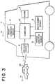
- FIG. 3 is a block diagram of another embodiment of a warning apparatus according to the present invention.
- Figure 4 is flow chart illustrating the operation of the embodiment of Figure 3.
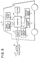
- FIG. 5 is a block diagram of still another embodiment of a warning apparatus according to the present invention.
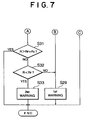
- Figures 6 and 7 are flow charts illustrating the operation of the embodiment of Figure 5.
- Figure 1 schematically illustrates a first embodiment of a warning apparatus installed on a first vehicle 1 in the form of an automobile travelling in the direction of the arrow at a velocity V 0 .
- a first vehicle 1 On the road ahead of the first vehicle 1 is an obstacle in the form of a second vehicle 20 travelling at a speed V F in the same direction as the first vehicle 1.
- the obstacle need not be moving, and it can be an object other than a vehicle, such as a pedestrian or an animal crossing the road.
- the first vehicle 1 is illustrated as being larger than the second vehicle 20, this is merely for ease of illustration, and the relative sizes of the first and second vehicles is not important.
- the warning apparatus includes an obstacle sensor 2, which can be any device capable of sensing the separation between the first vehicle 1 and the second vehicle 20.
- an obstacle sensor 2 can be any device capable of sensing the separation between the first vehicle 1 and the second vehicle 20.
- it can be a device which generates a beam of radiation, such as a beam of light waves, radar, radio waves, or ultrasonic waves, reflected off the second vehicle 20 and returns to the obstacle sensor 2.
- it can be an imaging device which forms an image of the second vehicle 20 and measures the separation based on the image.
- the obstacle sensor 2 generates an output signal indicating the measured separation from the second vehicle 20 and provides the output signal to a controller in the form of a computer 10.
- Examples of methods that can be used by the obstacle sensor 2 to measure the separation from the second vehicle 20 include triangulation and stereo processing of a plurality of video images. Based on the time rate of change of the separation, the relative speed of the first and second vehicles as well as the speed of the second vehicle 20 can be determined.
- the obstacle sensor 2 could also be a device which receives information transmitted from a sensor mounted on or along the road and which calculates the separation between the vehicles and their relative speed based on the transmitted information.
- a vehicle condition sensor 3 senses ore or more operating conditions of the first vehicle 1, such as the vehicle speed, the engine rotational speed, the engine torque, the vehicle acceleration, the steering angle of the steering wheel, or the yaw rate of the speed change ratio. Sensors for sensing such parameters are well known to those skilled in the art, and one or more such conventional sensors can be employed as the vehicle condition sensor 3. An output signal indicating the condition or conditions detected by the vehicle condition sensor 3 is input to the computer 10 by the vehicle condition sensor 3.
- a driver condition sensor 4 senses one or more conditions indicative of the physical or mental state of the driver of the first vehicle 1 and generates a corresponding output signal which is input to the computer 10.
- the driver condition sensor 4 can be a device which senses when the driver is tired, napping, or looking away from the road, or it can sense any other condition in which the driver's reaction time is expected to be impaired. These conditions can be sensed either directly or indirectly. For example, when the driver is manipulating one of the accessories of the vehicle such as the air conditioner, the radio, the cigarette lighter, or a car telephone, it can be inferred that the driver is looking away from the road and therefore requires longer to react to a warning.
- the computer 10 determines when a dangerous condition exists, i.e., a condition when the separation between the first and second vehicles is too small given the present speeds of the two vehicles, and in response it controls an alarm 5 to generate a warning.
- a dangerous condition i.e., a condition when the separation between the first and second vehicles is too small given the present speeds of the two vehicles.
- Any type of warning device can be used as the alarm 5, such as a buzzer, a chime, a computer-generated voice, or a flashing light.
- the alarm 5 warns the driver of the first vehicle 1 to slow down or take evasive action so as not to collide with the second vehicle 20.
- FIG. 2 illustrates an example of a routine performed by the computer 10 to control the operation of the embodiment illustrated in Figure 1.
- the computer 10 reads in data from each of sensors 2 - 4.
- the computer 10 determines whether the relative speed V F - V 0 of the first and second vehicles is greater than 0, wherein V F is the speed of the second vehicle 20 and V 0 is the speed of the first vehicle 1.
- the relative speed can be calculated by the computer 10 based on the time rate of change of the vehicle separation R determined by the obstacle sensor 2. If the relative speed is positive, i.e., if the separation between the two vehicles is increasing, then in Step S3, it is determined whether the vehicle separation R is greater than kV 0 , wherein k is a coefficient determined by the computer 10.
- k can be a constant, or it can varied by the computer 10 as described below. If the separation R is less than or equal to kV 0 , then in Step S4, the computer 10 controls the alarm 5 to generate a first warning to caution the driver.
- Step S2 if the relative speed is negative, it means that the first vehicle 1 is growing closer to the second vehicle 20, so in Step S5, the computer 10 calculates the minimum required vehicle separation R F required for the first vehicle 1 to decelerate from its present speed of V 0 to the same speed V F as the second vehicle 20 without colliding with the second vehicle 20 upon the driver of the first vehicle 1 being given a warning by the alarm 5 to slow down.
- Step S6 the computer 10 determines whether the actual separation R between the first and second vehicles is greater than R F + R 0 , wherein is a predetermined safety factor, such as the value kV 0 used in Step S3. If the vehicle separation R is less than or equal to this sum, then in Step S7 it is determined whether the vehicle separation R is less than R F . If R is greater than or equal to R F , then the driver can safely slow down the first vehicle 1 with a normal deceleration ⁇ , so in Step S4, the alarm 5 is driven to generate the first warning.
- R F + R 0 wherein is a predetermined safety factor, such as the value kV 0 used in Step S3. If the vehicle separation R is less than or equal to this sum, then in Step S7 it is determined whether the vehicle separation R is less than R F . If R is greater than or equal to R F , then the driver can safely slow down the first vehicle 1 with a normal deceleration ⁇ , so in Step S4, the alarm 5 is driven to generate the first warning.
- Step S7 if the vehicle separation R is smaller than R F , then a dangerous situation exists, because if the second vehicle 20 continues at its present speed, braking of the first vehicle at the normal deceleration ⁇ can not avert a collision. Therefore, in Step S8, the alarm 5 is driven to generate a second warning which alerts the driver to take immediate evasive action, such as stepping more firmly on the brakes or turning the steering wheel to avoid the second vehicle 20.
- Step S3 if the vehicle separation R is larger than kV 0 , or in Step S6, if the vehicle separation is larger than R F + R 0 , there is no immediate danger of a collision, so a warning is not generated and the routine is ended.
- the value of the vehicle separation R at which the first and second warnings are generated is varied by the computer 10 in accordance with the condition of the driver as indicated by the driver condition sensor 4. For example, when it is sensed that the driver is tired or sleepy or looking away from the road, the computer 10 can increase one or more of the variables R 0 , k, or t 0 . Increasing any of these variables will increase the value of the separation R at which a warning is generated and thereby ensure that the driver has sufficient time after generation of a warning to brake the first vehicle 1 without colliding with the second vehicle 2.
- Figure 3 illustrates another embodiment of the present invention installed on a first vehicle 1.
- the overall structure of this embodiment is similar to that of the previous embodiment, and elements 2 - 5 can have the same structure as described with respect to Figure 1.
- This embodiment further includes an environment sensor 6 which senses one or more conditions of the environment in which the first vehicle 1 is travelling and generates a corresponding output signal, which is provided to the computer 10.
- the environment sensor 6 detects an environmental condition which affects the distance required for the driver to stop the first vehicle 1, such as the presence of rain or wind, or it can detect an environmental condition which affects the driver's reaction speed, such as fog. These conditions can be detected either directly or indirectly.
- a rain or fog sensor could be installed on the road, and the environment sensor 6 could be a device which receives signals transmitted by the rain or fog sensor.
- the occurrence of rain or fog could be indirectly sensed by detecting when the driver of the first vehicle 1 turns on windshield wipers or fog lamps.
- the computer 10 receives the signals generated by sensors 2 - 4 and 6 and determines when a dangerous condition exists, upon which it drives the alarm 5 to generate a warning.
- Step S11 the computer 10 reads in data from each of sensors 2 - 4 and 6.
- Step S12 the computer 10 determines whether the relative speed V F - V 0 of the first and second vehicles is greater than 0. If the relative speed is greater than zero, then in Step S13, it is determined whether the vehicle separation R is greater than kV 0 . If the separation R is less than or equal to kV 0 , then in Step S14, the computer 10 drives the alarm 5 and a first warning is generated to caution the driver.
- Step S12 if the relative speed is negative, it means that the first vehicle 1 is growing closer to the second vehicle 20, so in Step S15, the computer 10 calculates by means of Equation (1) the minimum required vehicle separation R F for the driver to decelerate from the current speed V 0 to the speed V F of the second vehicle 20 without colliding with the second vehicle 20 assuming a rate of deceleration a produced by braking.
- Step S16 the computer 10 determines whether the actual separation R between the first and second vehicles is greater than R F + R 0 . If the vehicle separation R is less than or equal to this sum, then in Step S17 it is determined whether the vehicle separation R is less than R F . If R is greater than or equal to R F , then the driver can safely slow down the first vehicle 1 with a normal deceleration ⁇ , so in Step S14, the alarm 5 is driven to generate the first warning.
- Step S18 the alarm 5 is driven to generate a second warning which alerts the driver to take immediate evasive action, such as stepping more firmly on the brakes or turning the steering wheel to avoid the second vehicle 20.
- Step S13 if the vehicle separation R is larger than kV 0 , or in Step S16, if the vehicle separation is larger than R F + R 0 , there is no immediate danger of a collision, so a warning is not generated and the routine is ended.
- the value of one or more of R 0 , k, and t 0 can be varied in accordance with the physical or mental state of the driver as sensed by the driver condition sensor 4 so that the first and second warnings are generated earlier, i.e., at a large vehicle separation R when the driver is fatigued or looking away from the road.
- the first and second warnings are generated earlier when the environmental conditions are such as to increase the stopping distance of the first vehicle 1 or decrease the reaction time of the driver. For example, when the road on which the first vehicle 1 is travelling is wet, the rate of deceleration of the first vehicle 1 upon the driver's activating the brakes will be lower than on a dry road surface.
- the computer 10 can vary the value of ⁇ in Equation (1) so as to increase when the environment sensor 6 detects strong rain. By decreasing ⁇ , the value of R F will be increased, so the warnings will be generated earlier.
- one or more of R 0 , k, and t 0 can be adjusted in accordance with the environmental condition sensor by the environment sensor 6. For example, R 0 , k, or t 0 can be increased when the environment sensor 6 detects rain.
- the conditions for generation of a warning by the alarm 6 are varied in accordance with both the physical or mental state of the driver and environmental conditions, so the safety of the first vehicle 1 can be greatly increased.
- this embodiment employs both a driver condition sensor 4 and an environment sensor 6, it is possible for a warning apparatus according to the present invention to be equipped with only the environment sensor 6 without the driver condition sensor 4, and for the conditions for generating a warning to be varied in accordance with the environmental conditions.
- Figure 5 illustrate yet another embodiment of the present invention installed on a first vehicle 1.
- the structure of this embodiment is similar to that of the embodiment of Figure 3, but it further includes an operating amount sensor 7 and a learning device 8.
- the operating amount sensor 7 senses one or more parameters related to the operation of equipment manipulated by the driver as he drives the first vehicle 1, and it generates a corresponding output signal which is provided to the computer 10.
- a few examples of the operating amount sensor 7 are a sensor for sensing the speed of depression of the accelerator pedal, a sensor for sensing the force applied by the driver to the brake pedal, or a sensor which senses the steering angle of the steering wheel of the first vehicle 1.
- the learning device 8 receives the output signals from the vehicle condition sensor 3 and the operating amount sensor 7 and performs statistical processing to numerically evaluate the driving characteristics of the driver based on sensed operating characteristics such as the speed and force with which the driver operates the brakes, the accelerator pedal, or the steering wheel and the speed with which he accelerates and decelerates the vehicle.
- driving characteristics vary in accordance with the physical and mental state of the driver.
- the learning device 8 determines from the manner of operation of the first vehicle 1 when the driver is alert and when the driver is tired.
- the computer 10 delays the generation of the warnings by the alarm 5, i.e., decreases the vehicle separation R at which a warning is generated towards some predetermined limit so as to reflect the fast reaction time of the driver in his current condition.
- the computer 10 causes the warnings to be generated earlier by the alarm 5, i.e., at a larger value of R to compensate for the delayed reaction time of the driver caused by his fatigue.
- Step S21 the computer 10 reads in data from each of sensors 2 - 4 and 6 - 8.
- Step S22 the computer 10 determines whether the current operating conditions of the first vehicle 1 are suitable for performing learning. For example, suitable conditions can be when a predetermined length of time has passed since the first vehicle 1 has started or when a predetermined vehicle speed has been reached.
- Step S23 the present operating conditions are compared with either conditions which were set at an initial stage (if this is the first pass through the routine) or with operating condition learned by the learning device 8 (if this is the second or higher pass through the routine). Based on this comparison, the values of k, R 0 , and t 0 are set in Step S24.
- Step 22 if it is determined that conditions for performing learning have been established, then in Step S25, the learning device 8 performs statistical evaluation of the data from the vehicle condition sensor 3 and the operating amount sensor 7 and determines the driving characteristics of the driver of the first vehicle 1.
- Step S26 the characteristics determined in Step S25 are stored in an unillustrated memory.
- Step S24 based on the driving characteristics determined by the learning device 8, the values of k, R 0 , and t 0 are adjusted.
- Step S27 the computer 10 determines whether the relative speed V F - V 0 of the first and second vehicles is greater than 0. If the relative speed is greater than zero, then in Step S28, it is determined whether the vehicle separation R is greater than kV 0 . If the separation R is less than or equal to kV 0 , then in Step S29, the computer 10 drives the alarm 5 and a first warning is generated to caution the driver.
- Step S27 if the relative speed is less than or equal to zero, in Step S30, the computer 10 calculates by means of Equation (1) the minimum required separation R F for the driver to decelerate from the current speed V 0 to the speed V F of the second vehicle 20 without colliding with the second vehicle 20 assuming a rate of deceleration ⁇ .
- Step S31 the computer 10 determines whether the actual separation R between the first and second vehicles is greater than R F + R 0 . If the vehicle separation R is less than or equal to this sum, then in Step S32 it is determined whether the vehicle separation R is less than R F . If R is greater than or equal to R F , then the driver can safely slow down the first vehicle 1 with a normal deceleration ⁇ , so in Step S29, the alarm 5 is driven to generate the first warning.
- Step S33 the alarm 5 is driven to generate a second warning which alerts the driver to take immediate evasive action, such as stepping more firmly on the brakes or turning the steering wheel to avoid the second vehicle 20.
- Step S28 if the vehicle separation R is larger than kV 0 , or in Step S31, if the vehicle separation is larger than R F + R 0 , there is no immediate danger of a collision, so a warning is not generated and the routine is ended.
- the values of one or more of R 0 , k, and t 0 are varied in accordance with the physical or mental state of the driver as sensed by the driver condition sensor 4 and the environmental condition sensed by the environment sensor 6 so that the conditions which must be met for a warning to be generated, i.e., the vehicle separation R at which a warning is generated are set so that the driver will always have enough time to react to a warning generated by the alarm 5 to prevent a collision.
- the computer 10 adjusts the conditions for generating a warning based on input signals from the driver condition sensor 4, the environment sensor 6, and the learning device 8.
- the computer 10 it is also possible for the computer 10 to adjust the conditions for generating a warning based only on input signals from the learning device 8, or based on input signals from the learning device 8 and only one of the driver condition sensor 4 and the environment sensor 6. Therefore, it is possible to omit one or both of sensors 4 and 6.
- the timing of the warnings will be suitable for the existing circumstances at any given time. Therefore, the driver of a vehicle equipped with the present invention will not be annoyed by unnecessary generation of warnings, and the vehicle can be made both safe and pleasant to drive.
Landscapes
- Engineering & Computer Science (AREA)
- Remote Sensing (AREA)
- Radar, Positioning & Navigation (AREA)
- Physics & Mathematics (AREA)
- General Physics & Mathematics (AREA)
- Computer Networks & Wireless Communication (AREA)
- Electromagnetism (AREA)
- Human Computer Interaction (AREA)
- Mechanical Engineering (AREA)
- Traffic Control Systems (AREA)
- Control Of Driving Devices And Active Controlling Of Vehicle (AREA)
- Emergency Alarm Devices (AREA)
- Alarm Systems (AREA)
- Optical Radar Systems And Details Thereof (AREA)
Claims (10)
- Dispositif d'alarme pour véhicule, comportant :
des moyens de détection d'obstacle pour détecter la distance de séparation entre un véhicule et un obstacle situé en avant du véhicule,
une alarme,
une unité de commande destinée à établir une valeur pour la distance de séparation du véhicule, et
des moyens de génération d'un signal d'alarme pour commander à l'alarme de générer un signal d'alarme pour le conducteur lorsque la distance de séparation détectée par les moyens de détection d'obstacle est en dessous de la valeur établie pour la distance de séparation du véhicule,
caractérisé en ce qu'il comporte
des moyens de détection de l'état du conducteur destinés à détecter l'état physique ou mental du conducteur du véhicule, qui comportent des moyens pour détecter lorsque le conducteur manipule un accessoire du véhicule,
ladite unité de commande comportant des moyens d'établissement d'état sensibles aux moyens de détection de l'état du conducteur pour établir une valeur pour la distance de séparation du véhicule qui varie en fonction de l'état détecté du conducteur et augmente la valeur établie pour la distance de séparation du véhicule lorsque les moyens de détection de l'état du conducteur détectent que le conducteur manipule un accessoire. - Dispositif d'alarme selon la revendication 1, caractérisé en ce qu'il comporte des moyens de détection de l'environnement pour détecter un état d'environnement d'un environnement contenant le véhicule, dans lequel les moyens d'établissement d'état comportent des moyens pour faire varier la valeur établie pour la distance de séparation du véhicule conformément aux changements détectés de l'état de l'environnement.
- Dispositif d'alarme selon la revendication 2, caractérisé en ce que les moyens de détection de l'environnement comportent des moyens pour détecter la pluie, et les moyens d'etablissement d'état augmentent la valeur établie pour la distance de séparation du véhicule lorsque le détecteur d'environnement détecte une pluie.
- Dispositif d'alarme selon la revendication 1, caractérisé en ce qu'il comporte des moyens pour déterminer une caractéristique de conduite du conducteur, dans lequel les moyens d'établissement d'état font varier la valeur de la distance de séparation du véhicule conformément à la caractéristique de conduite déterminée.
- Dispositif d'alarme selon la revendication 4, caractérisé en ce que lesdits moyens pour déterminer une caractéristique de conduite du conducteur comportant un détecteur de quantité d'actionnement (7) et un dispositif d'apprentissage (8), dans lesquels le détecteur de quantité d'actionnement (7) détecte un ou plusieurs paramètres concernant le fonctionnement d'un équipement manipulé par le conducteur afin de conduire ledit véhicule, et le dispositif d'apprentissage (8) détermine la caractéristique de conduite à partir de la manière d'agir dudit véhicule.
- Dispositif d'alarme selon la revendication 1, comportant des moyens de détection de vitesse pour détecter la vitesse du véhicule VO, caractérisé en ce que
l'unité de commande comporte des moyens pour détecter la vitesse relative (VO - VF) du véhicule et de l'obstacle sur la base de la distance de séparation détectée par le détecteur d'obstacle, dans laquelle VF est la vitesse de l'obstacle,
les moyens d'établissement d'état établissent la valeur de la distance de séparation du véhicule à kVO, dans lequel k est une valeur qui est modifiée par les moyens d'établissement d'état conformément aux changements détectés d'état du conducteur, et
les moyens de génération d'un signal d'une alarme commandent à l'alarme de déclencher un signal d'alarme lorsque la vitesse relative diminue et que la distance de séparation du véhicule est plus faible que kVO. - Dispositif d'alarme selon la revendication 1, caractérisé en ce que l'unité de commande comporte des moyens pour détecter la vitesse relative (VO - VF) du véhicule et de l'obstacle sur la base de la distance de séparation détectée par le détecteur d'obstacle, dans laquelle VO est la vitesse du véhicule et VF est la vitesse de l'obstacle, et
les moyens d'établissement d'état établissent la valeur pour la distance de séparation du véhicule à
- Dispositif d'alarme pour un véhicule comportant :
des moyens de détection d'obstacle pour détecter la distance de séparation entre un véhicule et un obstacle,
une alarme,
une unité de commande destinée à établir une valeur pour la distance de séparation du véhicule, et
des moyens de génération d'un signal d'alarme pour commander à l'alarme de générer un signal d'alarme pour le conducteur lorsque la distance de séparation détectée par les moyens de détection d'obstacle est située en dessous de la valeur établie pour la distance de séparation du véhicule,
caractérisé en ce qu'il comporte
des moyens de détermination d'une caractéristique de conduite pour déterminer une caractéristique de conduite du conducteur du véhicule sur la base d'un ou plusieurs paramètres concernant le fonctionnement d'un équipement manipulé par le conducteur, lesdits moyens de détermination d'une caractéristique de conduite contenant un détecteur de quantité d'actionnement (7) et un dispositif d'apprentissage (8), dans lesquels le détecteur de quantité d'actionnement (7) détecte un ou plusieurs paramètres concernant le fonctionnement de l'équipement manipulé par le conducteur, et le dispositif d'apprentissage (8) détermine la caractéristique de conduite à partir de la manière de fonctionner dudit véhicule,
ladite unité de commande comportant des moyens d'établissement d'état pour établir une valeur pour la distance de séparation du véhicule qui varie en fonction des changements de la caractéristique de conduite déterminée. - Procédé pour générer un signal d'alarme pour un conducteur de véhicule comprenant les étapes, consistant à :
détecter une distance de séparation entre un véhicule et un obstacle situé en avant d'un véhicule,
établir une valeur pour la distance de séparation du véhicule entre le véhicule et l'obstacle, et
générer un signal d'alarme pour le conducteur lorsque la distance détectée est en dessous de la valeur établie pour la distance de séparation du véhicule,
caractérisé en ce qu'il comporte les étapes consistant à :
détecter un état physique ou mental du conducteur du véhicule, qui comprend la détection lorsque le conducteur manipule un accessoire du véhicule,
établir ladite valeur pour la distance de séparation du véhicule conformément à l'état détecté du conducteur et augmenter la valeur établie pour la distance de séparation du véhicule lorsqu'il est détecté que le conducteur manipule un accessoire. - Procédé pour générer un signal d'alarme pour un conducteur d'un véhicule comprenant les étapes, consistant à :
détecter une distance de séparation entre un véhicule et un obstacle situé en avant du véhicule,
établir une valeur pour la distance de séparation du véhicule entre le véhicule et l'obstacle, et
générer un signal d'alarme pour le conducteur lorsque la distance détectée est en dessous de la valeur établie pour la distance de séparation du véhicule,
caractérisé en ce qu'il comporte les étapes consistant à :
déterminer une caractéristique de conduite du conducteur du véhicule sur la base de la manière de fonctionner dudit véhicule, en détectant la quantité d'actionnement associée à un ou plusieurs paramètres concernant le fonctionnement d'un équipement manipulé par le conducteur, et
établir ladite valeur de la distance de séparation du véhicule conformément à la caractéristique de conduite déterminée.
Applications Claiming Priority (2)
| Application Number | Priority Date | Filing Date | Title |
|---|---|---|---|
| JP3319034A JPH05155291A (ja) | 1991-12-03 | 1991-12-03 | 車両用警報装置 |
| JP319034/91 | 1991-12-03 |
Publications (3)
| Publication Number | Publication Date |
|---|---|
| EP0549909A2 EP0549909A2 (fr) | 1993-07-07 |
| EP0549909A3 EP0549909A3 (en) | 1994-05-18 |
| EP0549909B1 true EP0549909B1 (fr) | 1996-08-28 |
Family
ID=18105779
Family Applications (1)
| Application Number | Title | Priority Date | Filing Date |
|---|---|---|---|
| EP92120574A Expired - Lifetime EP0549909B1 (fr) | 1991-12-03 | 1992-12-02 | Dispositif d'alarme pour véhicule |
Country Status (4)
| Country | Link |
|---|---|
| US (1) | US5432509A (fr) |
| EP (1) | EP0549909B1 (fr) |
| JP (1) | JPH05155291A (fr) |
| DE (1) | DE69213196T2 (fr) |
Cited By (4)
| Publication number | Priority date | Publication date | Assignee | Title |
|---|---|---|---|---|
| DE10060736A1 (de) * | 2000-12-07 | 2002-06-13 | Opel Adam Ag | Kraftfahrzeug mit Fahrerassistenzsystemen |
| WO2005055171A1 (fr) * | 2003-11-28 | 2005-06-16 | Robert Bosch Gmbh | Procede et dispositif pour alerter le conducteur d'un vehicule automobile |
| US7592920B2 (en) | 2004-08-12 | 2009-09-22 | Bayerische Motoren Werke Aktiengesellschaft | Systems and methods for evaluating driver attentiveness for collision avoidance |
| US11358593B2 (en) | 2019-07-09 | 2022-06-14 | King Fahd University Of Petroleum And Minerals | Dual direction accident prevention and assistive braking system |
Families Citing this family (102)
| Publication number | Priority date | Publication date | Assignee | Title |
|---|---|---|---|---|
| EP0841648B1 (fr) * | 1992-09-30 | 2004-06-02 | Hitachi, Ltd. | Système d'aide à la conduite et véhicule avec un tel système |
| JP2817110B2 (ja) * | 1993-11-17 | 1998-10-27 | 本田技研工業株式会社 | 車両用警報装置 |
| JPH07251651A (ja) * | 1994-03-15 | 1995-10-03 | Nissan Motor Co Ltd | 車間距離制御装置 |
| GB2291244B (en) * | 1994-07-15 | 1998-02-11 | Design Technology & Innovation | Vehicle safety systems |
| US5642093A (en) * | 1995-01-27 | 1997-06-24 | Fuji Jukogyo Kabushiki Kaisha | Warning system for vehicle |
| GB2303011B (en) * | 1995-06-29 | 1999-06-23 | Roderick Angel | Collision avoidance radar for land vehicles |
| US5652705A (en) * | 1995-09-25 | 1997-07-29 | Spiess; Newton E. | Highway traffic accident avoidance system |
| US5642869A (en) * | 1995-12-01 | 1997-07-01 | Teleengineering, Inc. | Apparatus for detecting the distance between two objects |
| KR100201256B1 (ko) * | 1996-08-27 | 1999-06-15 | 윤종용 | 음성을 이용한 차량 시동 제어장치 |
| CA2271797C (fr) * | 1996-11-14 | 2002-08-13 | Auto-Sense Ltd. | Systeme de detection presentant une tolerance au bruit amelioree |
| DE19648826A1 (de) * | 1996-11-26 | 1997-06-12 | Johannes Hanusch | Kollosionswarnsystem für Fahrzeuge mittels elektronischer Bildauswertung |
| JPH10166895A (ja) * | 1996-12-09 | 1998-06-23 | Mitsubishi Electric Corp | 車両用追従走行制御装置 |
| US6275231B1 (en) * | 1997-08-01 | 2001-08-14 | American Calcar Inc. | Centralized control and management system for automobiles |
| US6483441B1 (en) * | 1997-09-02 | 2002-11-19 | Thomas F. Hinde | Distance indicating device and method |
| JP3677965B2 (ja) * | 1997-09-17 | 2005-08-03 | 日産自動車株式会社 | 車両用追突警報装置 |
| US6201236B1 (en) | 1997-11-13 | 2001-03-13 | Auto Sense Ltd. | Detection system with improved noise tolerance |
| DE19806687A1 (de) * | 1998-02-18 | 1999-08-26 | Daimler Chrysler Ag | Verfahren zur Verhinderung einer Kollision eines Fahrzeugs mit einem vor dem Fahrzeug angeordneten Hindernis und Bremsvorrichtung |
| GB2340646A (en) * | 1998-08-14 | 2000-02-23 | Nicholas Francis Barrow | Vehicle braking distance warning system incorporating assessment of driver |
| US6060989A (en) * | 1998-10-19 | 2000-05-09 | Lucent Technologies Inc. | System and method for preventing automobile accidents |
| DE19900314C2 (de) * | 1999-01-07 | 2000-10-19 | Daimler Chrysler Ag | Verfahren und Vorrichtung zur Abbremsung eines Kraftfahrzeugs im Nahbereich mit einem Hindernis |
| JP3495934B2 (ja) * | 1999-01-08 | 2004-02-09 | 矢崎総業株式会社 | 事故防止システム |
| US6225918B1 (en) | 1999-02-19 | 2001-05-01 | Bing Kam | Automatic warning signal system for vehicles |
| DE19921488A1 (de) * | 1999-05-08 | 2000-11-16 | Bosch Gmbh Robert | Verfahren und Vorrichtung zur Überwachung des Innenraums und des Umfeldes eines Fahrzeugs |
| JP3998855B2 (ja) * | 1999-05-18 | 2007-10-31 | 三菱電機株式会社 | 危険接近防止装置 |
| US6310542B1 (en) | 1999-08-19 | 2001-10-30 | Lucent Technologies Inc. | Cognitive system for a vehicle and its occupants |
| US6167333A (en) * | 1999-08-19 | 2000-12-26 | Lucent Technologies Inc. | Highway information system |
| JP3174832B2 (ja) * | 1999-10-27 | 2001-06-11 | 建設省土木研究所長 | 横断歩行者衝突防止システム |
| US6763292B1 (en) * | 2000-06-21 | 2004-07-13 | International Business Machines Corporation | Prediction and compensation for land vehicle dynamics based on feedforward road conditions |
| DE10161262B4 (de) * | 2000-06-23 | 2006-04-20 | Daimlerchrysler Ag | Verfahren und Vorrichtung zur Aufmerksamkeitsteurung für Bediener einer technischen Einrichtung, basierend auf Infrarot-Bilddaten |
| DE10030813B4 (de) * | 2000-06-23 | 2004-02-12 | Daimlerchrysler Ag | Aufmerksamkeitssteuerung für Bediener einer technischen Einrichtung |
| US6505123B1 (en) | 2000-07-24 | 2003-01-07 | Weatherbank, Inc. | Interactive weather advisory system |
| DE10103922A1 (de) * | 2001-01-30 | 2002-08-01 | Physoptics Opto Electronic Gmb | Interaktives Datensicht- und Bediensystem |
| JP2002316633A (ja) * | 2001-04-20 | 2002-10-29 | Fuji Heavy Ind Ltd | 車両運動制御装置 |
| JP4230124B2 (ja) * | 2001-04-20 | 2009-02-25 | 富士重工業株式会社 | 車両運動制御装置 |
| JP2003104147A (ja) * | 2001-09-27 | 2003-04-09 | Mazda Motor Corp | 車両の逸脱警報装置 |
| DE10152852A1 (de) * | 2001-10-25 | 2003-05-22 | Daimler Chrysler Ag | System zur Bestimmung und Beeinflussung der emotionalen Verfassung des Fahrers eines Kraftfahrzeugs |
| DE10153302A1 (de) * | 2001-10-31 | 2003-05-22 | Daimler Chrysler Ag | Regelung von Warn- und Informationssystemen |
| US6679702B1 (en) | 2001-12-18 | 2004-01-20 | Paul S. Rau | Vehicle-based headway distance training system |
| US6559762B1 (en) | 2002-01-02 | 2003-05-06 | Ford Global Technologies, Llc | Multi channel braking notification system |
| US6721632B2 (en) | 2002-02-05 | 2004-04-13 | International Business Machines Corporation | Wireless exchange between vehicle-borne communications systems |
| JP2003276470A (ja) * | 2002-03-22 | 2003-09-30 | Nissan Motor Co Ltd | 情報提示制御装置 |
| DE10220567A1 (de) * | 2002-05-08 | 2003-11-20 | Volkswagen Ag | Automatisches Notmanöver eines Kraftfahrzeugs |
| US7365651B2 (en) * | 2002-08-20 | 2008-04-29 | Motorola, Inc. | Method and apparatus for selecting a user interface |
| DE10244205A1 (de) * | 2002-09-23 | 2004-03-25 | Robert Bosch Gmbh | Verfahren und Einrichtung zur Verhinderung der Kollision von Fahrzeugen |
| DE10249003B4 (de) * | 2002-10-21 | 2006-09-07 | Sassin, Wolfgang, Dr. | Verfahren und Vorrichtung zur Signalisierung eines zeitlich und räumlich variierenden Gefahrenpotentials für den ein technisches Gerät oder eine Maschine bedienenden Operator |
| JP3873919B2 (ja) * | 2003-03-20 | 2007-01-31 | 日産自動車株式会社 | 車線逸脱防止装置 |
| KR100513009B1 (ko) * | 2003-04-04 | 2005-09-05 | 삼성전자주식회사 | 경고를 제한적으로 출력하는 네비게이션시스템과네비게이션시스템에서 경고를 제한적으로 출력하는 경고발생장치 및 그 방법 |
| WO2004102500A1 (fr) * | 2003-05-16 | 2004-11-25 | Fujitsu Limited | Systeme d'alarme, dispositif de commande d'alarme et programme de commande d'alarme |
| DE10335732A1 (de) * | 2003-08-05 | 2005-02-24 | Daimlerchrysler Ag | Verfahren zum Ändern des Beschleunigungsmodus eines Kraftfahrzeugs |
| DE10336681B4 (de) * | 2003-08-09 | 2005-07-07 | Audi Ag | Kraftfahrzeug |
| JP4316960B2 (ja) * | 2003-08-22 | 2009-08-19 | 株式会社半導体エネルギー研究所 | 装置 |
| DE10339647A1 (de) * | 2003-08-28 | 2005-03-24 | Robert Bosch Gmbh | Vorrichtung zur Fahrerwarnung |
| JP4496759B2 (ja) * | 2003-10-29 | 2010-07-07 | 日産自動車株式会社 | 車線逸脱防止装置 |
| DE102004048013A1 (de) * | 2004-10-01 | 2006-04-06 | Robert Bosch Gmbh | Verfahren und Vorrichtung zur Fahrerunterstützung |
| JP2006130010A (ja) * | 2004-11-04 | 2006-05-25 | Denso Corp | 視覚認識支援装置 |
| US20060161469A1 (en) * | 2005-01-14 | 2006-07-20 | Weatherbank, Inc. | Interactive advisory system |
| JP4766417B2 (ja) * | 2005-02-22 | 2011-09-07 | 独立行政法人産業技術総合研究所 | 行動支援装置 |
| JP4534789B2 (ja) * | 2005-02-22 | 2010-09-01 | トヨタ自動車株式会社 | 車両用警報装置 |
| DE102005011241A1 (de) * | 2005-03-11 | 2006-09-14 | Robert Bosch Gmbh | Verfahren und Vorrichtung zur Kollisionswarnung |
| DE502005002674D1 (de) * | 2005-08-02 | 2008-03-13 | Delphi Tech Inc | Verfahren zur Steuerung eines Fahrerassistenzsystems und dazugehörige Vorrichtung |
| JP4852941B2 (ja) * | 2005-09-05 | 2012-01-11 | トヨタ自動車株式会社 | 車載警報装置 |
| US8229467B2 (en) | 2006-01-19 | 2012-07-24 | Locator IP, L.P. | Interactive advisory system |
| US7426435B2 (en) * | 2006-09-21 | 2008-09-16 | Ford Global Technologies, Llc | Engine control system and method |
| EP2407947B8 (fr) * | 2006-10-13 | 2014-04-23 | Toyota Jidosha Kabushiki Kaisha | Appareil d'avertissement embarqué et procédé d'avertissement |
| US8634814B2 (en) | 2007-02-23 | 2014-01-21 | Locator IP, L.P. | Interactive advisory system for prioritizing content |
| GB2452262B (en) * | 2007-08-25 | 2010-10-20 | David Guest | 'Safe d' stopping distance reminder |
| DE102008019519A1 (de) * | 2008-04-18 | 2009-06-25 | Adc Automotive Distance Control Systems Gmbh | Verfahren zum Bestimmen des Sicherheitsabstands und/oder Regeln der Fahrzeuglängsgeschwindigkeit eines einem vorausfahrenden Fahrzeug nachfahrenden Fahrzeugs |
| WO2009141092A1 (fr) | 2008-05-21 | 2009-11-26 | Adc Automotive Distance Control Systems Gmbh | Système d'aide à la conduite destiné à éviter des collisions entre un véhicule motorisé et des piétons |
| JP5004887B2 (ja) * | 2008-07-16 | 2012-08-22 | 日立オートモティブシステムズ株式会社 | 車両運転支援装置 |
| EP2187236A1 (fr) * | 2008-11-06 | 2010-05-19 | Ford Global Technologies, LLC | Appareil d'avertissement de collision |
| JP5385056B2 (ja) * | 2009-08-31 | 2014-01-08 | 株式会社デンソー | 運転状況推定装置,運転支援装置 |
| US8799037B2 (en) | 2010-10-14 | 2014-08-05 | Palto Alto Research Center Incorporated | Computer-implemented system and method for managing motor vehicle parking reservations |
| US9292471B2 (en) | 2011-02-18 | 2016-03-22 | Honda Motor Co., Ltd. | Coordinated vehicle response system and method for driver behavior |
| US8698639B2 (en) * | 2011-02-18 | 2014-04-15 | Honda Motor Co., Ltd. | System and method for responding to driver behavior |
| US20140092252A1 (en) * | 2011-05-12 | 2014-04-03 | Magna Electronics Inc. | System and method for annotating video |
| US9132774B2 (en) | 2012-06-22 | 2015-09-15 | GM Global Technology Operations LLC | Alert systems and methods for a vehicle |
| US9123215B2 (en) | 2012-06-22 | 2015-09-01 | GM Global Technology Operations LLC | Alert systems and methods for a vehicle |
| US20130342365A1 (en) * | 2012-06-22 | 2013-12-26 | GM Global Technology Operations LLC | Alert systems and methods for a vehicle |
| US9266451B2 (en) | 2012-06-22 | 2016-02-23 | GM Global Technology Operations LLC | Alert systems and methods for a vehicle |
| US9701245B2 (en) | 2012-06-22 | 2017-07-11 | GM Global Technology Operations LLC | Alert systems and methods for a vehicle |
| US9349263B2 (en) | 2012-06-22 | 2016-05-24 | GM Global Technology Operations LLC | Alert systems and methods for a vehicle |
| US9153108B2 (en) | 2012-06-22 | 2015-10-06 | GM Global Technology Operations LLC | Alert systems and methods for a vehicle |
| US9421908B2 (en) | 2012-06-22 | 2016-08-23 | GM Global Technology Operations LLC | Alert systems and methods for a vehicle with improved actuator placement |
| JP6205640B2 (ja) * | 2012-07-30 | 2017-10-04 | 市光工業株式会社 | 車両用警告装置 |
| KR101957943B1 (ko) * | 2012-08-31 | 2019-07-04 | 삼성전자주식회사 | 정보 제공 방법 및 이를 위한 정보 제공 차량 |
| US9779365B2 (en) | 2012-09-21 | 2017-10-03 | Conduent Business Services, Llc | Computer-implemented system and method for managing interchangeable EV charging-capable parking spaces |
| US9064417B2 (en) | 2012-12-21 | 2015-06-23 | Palo Alto Research Center Incorporated | Computer-implemented system and method for directing users to available parking spaces |
| US9087453B2 (en) | 2013-03-01 | 2015-07-21 | Palo Alto Research Center Incorporated | Computer-implemented system and method for spontaneously identifying and directing users to available parking spaces |
| US20140278087A1 (en) * | 2013-03-14 | 2014-09-18 | Ford Global Technologies, Llc | Method and Apparatus for Predicting Times of High Driver Demand |
| US9751534B2 (en) | 2013-03-15 | 2017-09-05 | Honda Motor Co., Ltd. | System and method for responding to driver state |
| US9454905B2 (en) * | 2013-04-29 | 2016-09-27 | Global Foundries Inc. | Safe distance determination |
| US9925980B2 (en) * | 2014-09-17 | 2018-03-27 | Magna Electronics Inc. | Vehicle collision avoidance system with enhanced pedestrian avoidance |
| US9718405B1 (en) * | 2015-03-23 | 2017-08-01 | Rosco, Inc. | Collision avoidance and/or pedestrian detection system |
| EP3151216A1 (fr) * | 2015-10-01 | 2017-04-05 | Volvo Car Corporation | Procédé d'avertissement d'un conducteur de véhicule et système d'alerte |
| US10144419B2 (en) | 2015-11-23 | 2018-12-04 | Magna Electronics Inc. | Vehicle dynamic control system for emergency handling |
| US9776630B2 (en) * | 2016-02-29 | 2017-10-03 | Nissan North America, Inc. | Vehicle operation based on converging time |
| WO2019178506A1 (fr) * | 2018-03-15 | 2019-09-19 | Modular Mining Systems, Inc. | Chevauchement de zone projetée |
| US11113972B2 (en) | 2018-04-06 | 2021-09-07 | Precision Triatholon Systems Limited | Position detector and system |
| US10766412B1 (en) * | 2019-09-12 | 2020-09-08 | Toyota Motor Engineering & Manufacturing North America, Inc. | Systems and methods for notifying other road users of a change in vehicle speed |
| JP7368788B2 (ja) * | 2019-12-04 | 2023-10-25 | トヨタ自動車株式会社 | 車両制御装置 |
| KR20220082968A (ko) * | 2020-12-10 | 2022-06-20 | 현대자동차주식회사 | 차량 운전자의 시야 보조 방법 및 그 보조 장치 |
| US20240116530A1 (en) * | 2022-10-11 | 2024-04-11 | Toyota Motor Engineering & Manufacturing North America, Inc. | Object detection system |
Family Cites Families (11)
| Publication number | Priority date | Publication date | Assignee | Title |
|---|---|---|---|---|
| US3227998A (en) * | 1962-05-07 | 1966-01-04 | Ford Motor Co | Automobile driver attention indicator |
| DE2002012A1 (de) * | 1969-01-21 | 1970-08-13 | Del Signore Dr Giovanni | Vorrichtung und Verfahren zum Melden von Hindernissen und zur Anzeige der Entfernung der Hindernisse |
| FR2071418A5 (fr) * | 1969-12-29 | 1971-09-17 | Dessailly Rene | |
| DE2320613A1 (de) * | 1973-04-24 | 1974-11-14 | Zenger Ing Buero | Abstand-warngeraet |
| US3898652A (en) * | 1973-12-26 | 1975-08-05 | Rashid Mary D | Vehicle safety and protection system |
| JPS6042070B2 (ja) * | 1978-07-17 | 1985-09-20 | ヤマハ発動機株式会社 | 自動二輪車のフロントフオ−ク取付け構造 |
| JPS5522291A (en) * | 1978-08-05 | 1980-02-16 | Alps Electric Co Ltd | Manufacture of magnetic head |
| JPS5545412A (en) * | 1978-09-26 | 1980-03-31 | Maaberuto Kk | Processing of carpet for upstair |
| JPS57167845A (en) * | 1981-04-07 | 1982-10-15 | Honda Motor Co Ltd | Vehicle throttle reaction force control system |
| US4926170A (en) * | 1986-02-19 | 1990-05-15 | Auto-Sense, Ltd. | Object detection method and apparatus employing electro-optics |
| US5091726A (en) * | 1990-08-23 | 1992-02-25 | Industrial Technology Resarch Institute | Vehicle anti-collision system |
-
1991
- 1991-12-03 JP JP3319034A patent/JPH05155291A/ja active Pending
-
1992
- 1992-11-24 US US07/980,779 patent/US5432509A/en not_active Expired - Lifetime
- 1992-12-02 EP EP92120574A patent/EP0549909B1/fr not_active Expired - Lifetime
- 1992-12-02 DE DE69213196T patent/DE69213196T2/de not_active Expired - Lifetime
Cited By (4)
| Publication number | Priority date | Publication date | Assignee | Title |
|---|---|---|---|---|
| DE10060736A1 (de) * | 2000-12-07 | 2002-06-13 | Opel Adam Ag | Kraftfahrzeug mit Fahrerassistenzsystemen |
| WO2005055171A1 (fr) * | 2003-11-28 | 2005-06-16 | Robert Bosch Gmbh | Procede et dispositif pour alerter le conducteur d'un vehicule automobile |
| US7592920B2 (en) | 2004-08-12 | 2009-09-22 | Bayerische Motoren Werke Aktiengesellschaft | Systems and methods for evaluating driver attentiveness for collision avoidance |
| US11358593B2 (en) | 2019-07-09 | 2022-06-14 | King Fahd University Of Petroleum And Minerals | Dual direction accident prevention and assistive braking system |
Also Published As
| Publication number | Publication date |
|---|---|
| DE69213196D1 (de) | 1996-10-02 |
| JPH05155291A (ja) | 1993-06-22 |
| US5432509A (en) | 1995-07-11 |
| EP0549909A2 (fr) | 1993-07-07 |
| DE69213196T2 (de) | 1997-02-06 |
| EP0549909A3 (en) | 1994-05-18 |
Similar Documents
| Publication | Publication Date | Title |
|---|---|---|
| EP0549909B1 (fr) | Dispositif d'alarme pour véhicule | |
| US7200481B2 (en) | Driving assist system for vehicle | |
| US8150583B2 (en) | Method and apparatus for avoiding or mitigating vehicle collisions | |
| US6889140B2 (en) | Collision avoidance control system for vehicle | |
| US7034668B2 (en) | Threat level identification and quantifying system | |
| US8396642B2 (en) | Adaptive cruise control system | |
| US6037860A (en) | Method and arrangement for avoiding and/or minimizing vehicle collisions in road traffic | |
| US7184889B2 (en) | Collision-prediction unit for a vehicle | |
| JP3189560B2 (ja) | 車間距離検知装置および車間距離警報装置 | |
| EP0484995B1 (fr) | Méthode de commande de la vitesse d'un véhicule | |
| US20070296564A1 (en) | Rear collision warning system | |
| KR20200051085A (ko) | 차량 및 그 제어방법 | |
| JP2004521028A (ja) | 車両の減速を作動させて実施する方法および装置 | |
| US8103424B2 (en) | Inter-vehicle distance control apparatus and method for controlling inter-vehicle distance | |
| JP2004145883A (ja) | 前方衝突警告のための危険評価アルゴリズム | |
| JPH09188234A (ja) | 道路交通での衝突状況を回避およびまたは最小限に抑える装置 | |
| JP2008162553A (ja) | 車両用制御装置 | |
| KR20150051548A (ko) | 운전자의 성향을 반영하는 운전보조시스템 및 그 제어방법 | |
| JP3391091B2 (ja) | 車間距離警報装置 | |
| JPH06119599A (ja) | 車両走行制御装置 | |
| JPH07257302A (ja) | 車両の前方障害物警報装置 | |
| JP3157986B2 (ja) | 追突防止システムにおける追突危険性判断方法 | |
| JP3687156B2 (ja) | 自動車用追突警報装置 | |
| JP3088100B2 (ja) | 車間距離制御装置 | |
| JP2928051B2 (ja) | 車両用警報装置 |
Legal Events
| Date | Code | Title | Description |
|---|---|---|---|
| PUAI | Public reference made under article 153(3) epc to a published international application that has entered the european phase |
Free format text: ORIGINAL CODE: 0009012 |
|
| AK | Designated contracting states |
Kind code of ref document: A2 Designated state(s): DE FR GB |
|
| RIN1 | Information on inventor provided before grant (corrected) |
Inventor name: KAJIWATA, YASUYA, C/O MITSUBISHI DENKI K.K. |
|
| PUAL | Search report despatched |
Free format text: ORIGINAL CODE: 0009013 |
|
| AK | Designated contracting states |
Kind code of ref document: A3 Designated state(s): DE FR GB |
|
| 17P | Request for examination filed |
Effective date: 19940630 |
|
| 17Q | First examination report despatched |
Effective date: 19950524 |
|
| GRAH | Despatch of communication of intention to grant a patent |
Free format text: ORIGINAL CODE: EPIDOS IGRA |
|
| GRAH | Despatch of communication of intention to grant a patent |
Free format text: ORIGINAL CODE: EPIDOS IGRA |
|
| GRAA | (expected) grant |
Free format text: ORIGINAL CODE: 0009210 |
|
| AK | Designated contracting states |
Kind code of ref document: B1 Designated state(s): DE FR GB |
|
| REF | Corresponds to: |
Ref document number: 69213196 Country of ref document: DE Date of ref document: 19961002 |
|
| ET | Fr: translation filed | ||
| REG | Reference to a national code |
Ref country code: GB Ref legal event code: 727 |
|
| REG | Reference to a national code |
Ref country code: GB Ref legal event code: 727A |
|
| REG | Reference to a national code |
Ref country code: GB Ref legal event code: 727B |
|
| REG | Reference to a national code |
Ref country code: GB Ref legal event code: SP |
|
| PLBE | No opposition filed within time limit |
Free format text: ORIGINAL CODE: 0009261 |
|
| STAA | Information on the status of an ep patent application or granted ep patent |
Free format text: STATUS: NO OPPOSITION FILED WITHIN TIME LIMIT |
|
| 26N | No opposition filed | ||
| REG | Reference to a national code |
Ref country code: GB Ref legal event code: IF02 |
|
| REG | Reference to a national code |
Ref country code: GB Ref legal event code: 746 Effective date: 20100615 |
|
| PGFP | Annual fee paid to national office [announced via postgrant information from national office to epo] |
Ref country code: GB Payment date: 20101201 Year of fee payment: 19 |
|
| PGFP | Annual fee paid to national office [announced via postgrant information from national office to epo] |
Ref country code: DE Payment date: 20101124 Year of fee payment: 19 |
|
| PGFP | Annual fee paid to national office [announced via postgrant information from national office to epo] |
Ref country code: FR Payment date: 20111219 Year of fee payment: 20 |
|
| REG | Reference to a national code |
Ref country code: DE Ref legal event code: R071 Ref document number: 69213196 Country of ref document: DE |
|
| REG | Reference to a national code |
Ref country code: DE Ref legal event code: R071 Ref document number: 69213196 Country of ref document: DE |
|
| REG | Reference to a national code |
Ref country code: GB Ref legal event code: PE20 Expiry date: 20121201 |
|
| PG25 | Lapsed in a contracting state [announced via postgrant information from national office to epo] |
Ref country code: GB Free format text: LAPSE BECAUSE OF EXPIRATION OF PROTECTION Effective date: 20121201 |